EP2525221A1 - Kalibriersystem und -technik für photolumineszente Sauerstoffsensoren mit einem durch eine Metall-Luft-Batterie aufrechterhaltenen Nullpunkt - Google Patents
Kalibriersystem und -technik für photolumineszente Sauerstoffsensoren mit einem durch eine Metall-Luft-Batterie aufrechterhaltenen Nullpunkt Download PDFInfo
- Publication number
- EP2525221A1 EP2525221A1 EP12166808A EP12166808A EP2525221A1 EP 2525221 A1 EP2525221 A1 EP 2525221A1 EP 12166808 A EP12166808 A EP 12166808A EP 12166808 A EP12166808 A EP 12166808A EP 2525221 A1 EP2525221 A1 EP 2525221A1
- Authority
- EP
- European Patent Office
- Prior art keywords
- oxygen
- mass
- concentration
- probe
- calibration
- Prior art date
- Legal status (The legal status is an assumption and is not a legal conclusion. Google has not performed a legal analysis and makes no representation as to the accuracy of the status listed.)
- Granted
Links
- QVGXLLKOCUKJST-UHFFFAOYSA-N atomic oxygen Chemical compound [O] QVGXLLKOCUKJST-UHFFFAOYSA-N 0.000 title claims abstract description 285
- 239000001301 oxygen Substances 0.000 title claims abstract description 285
- 229910052760 oxygen Inorganic materials 0.000 title claims abstract description 285
- 238000000034 method Methods 0.000 title claims abstract description 31
- 239000000523 sample Substances 0.000 claims abstract description 84
- 238000004891 communication Methods 0.000 claims abstract description 32
- 230000007613 environmental effect Effects 0.000 claims abstract description 31
- 239000012530 fluid Substances 0.000 claims abstract description 31
- 230000000717 retained effect Effects 0.000 claims abstract description 18
- 230000003287 optical effect Effects 0.000 claims description 32
- 230000004888 barrier function Effects 0.000 claims description 13
- 239000000463 material Substances 0.000 claims description 13
- 239000011159 matrix material Substances 0.000 claims description 10
- 230000002000 scavenging effect Effects 0.000 claims description 8
- 230000036284 oxygen consumption Effects 0.000 claims description 7
- 230000002596 correlated effect Effects 0.000 claims description 5
- 230000004913 activation Effects 0.000 claims description 4
- 239000007788 liquid Substances 0.000 claims description 3
- 238000005424 photoluminescence Methods 0.000 claims description 3
- 239000000975 dye Substances 0.000 description 62
- 239000010410 layer Substances 0.000 description 49
- 239000000203 mixture Substances 0.000 description 45
- 239000011701 zinc Substances 0.000 description 17
- 125000006850 spacer group Chemical group 0.000 description 16
- HCHKCACWOHOZIP-UHFFFAOYSA-N Zinc Chemical compound [Zn] HCHKCACWOHOZIP-UHFFFAOYSA-N 0.000 description 15
- 229910052725 zinc Inorganic materials 0.000 description 13
- -1 palladium porphyrin Chemical class 0.000 description 10
- KWYUFKZDYYNOTN-UHFFFAOYSA-M Potassium hydroxide Chemical compound [OH-].[K+] KWYUFKZDYYNOTN-UHFFFAOYSA-M 0.000 description 9
- 239000012491 analyte Substances 0.000 description 8
- 239000004033 plastic Substances 0.000 description 7
- 229920003023 plastic Polymers 0.000 description 7
- PXHVJJICTQNCMI-UHFFFAOYSA-N Nickel Chemical compound [Ni] PXHVJJICTQNCMI-UHFFFAOYSA-N 0.000 description 6
- 239000003792 electrolyte Substances 0.000 description 6
- 239000010408 film Substances 0.000 description 6
- 239000004809 Teflon Substances 0.000 description 5
- 229920006362 Teflon® Polymers 0.000 description 5
- XLOMVQKBTHCTTD-UHFFFAOYSA-N Zinc monoxide Chemical compound [Zn]=O XLOMVQKBTHCTTD-UHFFFAOYSA-N 0.000 description 5
- 239000012790 adhesive layer Substances 0.000 description 5
- 238000004020 luminiscence type Methods 0.000 description 5
- KDLHZDBZIXYQEI-UHFFFAOYSA-N palladium Substances [Pd] KDLHZDBZIXYQEI-UHFFFAOYSA-N 0.000 description 5
- 238000006243 chemical reaction Methods 0.000 description 4
- 239000011521 glass Substances 0.000 description 4
- 239000012212 insulator Substances 0.000 description 4
- 230000014759 maintenance of location Effects 0.000 description 4
- 229910052751 metal Inorganic materials 0.000 description 4
- 239000002184 metal Substances 0.000 description 4
- 239000012466 permeate Substances 0.000 description 4
- 239000007789 gas Substances 0.000 description 3
- 238000005259 measurement Methods 0.000 description 3
- 239000012528 membrane Substances 0.000 description 3
- 229910052759 nickel Inorganic materials 0.000 description 3
- 229910052763 palladium Inorganic materials 0.000 description 3
- 229920000139 polyethylene terephthalate Polymers 0.000 description 3
- 239000005020 polyethylene terephthalate Substances 0.000 description 3
- 238000007789 sealing Methods 0.000 description 3
- 230000035945 sensitivity Effects 0.000 description 3
- 229940007718 zinc hydroxide Drugs 0.000 description 3
- 229910021511 zinc hydroxide Inorganic materials 0.000 description 3
- 229910000497 Amalgam Inorganic materials 0.000 description 2
- 229920002799 BoPET Polymers 0.000 description 2
- RYGMFSIKBFXOCR-UHFFFAOYSA-N Copper Chemical compound [Cu] RYGMFSIKBFXOCR-UHFFFAOYSA-N 0.000 description 2
- UFHFLCQGNIYNRP-UHFFFAOYSA-N Hydrogen Chemical compound [H][H] UFHFLCQGNIYNRP-UHFFFAOYSA-N 0.000 description 2
- 239000005041 Mylar™ Substances 0.000 description 2
- 229910000831 Steel Inorganic materials 0.000 description 2
- 239000000853 adhesive Substances 0.000 description 2
- 230000001070 adhesive effect Effects 0.000 description 2
- 230000005540 biological transmission Effects 0.000 description 2
- 238000010276 construction Methods 0.000 description 2
- 229910052802 copper Inorganic materials 0.000 description 2
- 239000010949 copper Substances 0.000 description 2
- 239000007799 cork Substances 0.000 description 2
- 239000001257 hydrogen Substances 0.000 description 2
- 229910052739 hydrogen Inorganic materials 0.000 description 2
- MILUBEOXRNEUHS-UHFFFAOYSA-N iridium(3+) Chemical compound [Ir+3] MILUBEOXRNEUHS-UHFFFAOYSA-N 0.000 description 2
- NUJOXMJBOLGQSY-UHFFFAOYSA-N manganese dioxide Chemical compound O=[Mn]=O NUJOXMJBOLGQSY-UHFFFAOYSA-N 0.000 description 2
- MQZFZDIZKWNWFX-UHFFFAOYSA-N osmium(2+) Chemical compound [Os+2] MQZFZDIZKWNWFX-UHFFFAOYSA-N 0.000 description 2
- 239000002245 particle Substances 0.000 description 2
- BASFCYQUMIYNBI-UHFFFAOYSA-N platinum Chemical compound [Pt] BASFCYQUMIYNBI-UHFFFAOYSA-N 0.000 description 2
- 229920002492 poly(sulfone) Polymers 0.000 description 2
- 239000004417 polycarbonate Substances 0.000 description 2
- 229920000515 polycarbonate Polymers 0.000 description 2
- 229920000642 polymer Polymers 0.000 description 2
- 229920001296 polysiloxane Polymers 0.000 description 2
- 229910052707 ruthenium Inorganic materials 0.000 description 2
- 239000007787 solid Substances 0.000 description 2
- 239000010959 steel Substances 0.000 description 2
- UGZADUVQMDAIAO-UHFFFAOYSA-L zinc hydroxide Chemical compound [OH-].[OH-].[Zn+2] UGZADUVQMDAIAO-UHFFFAOYSA-L 0.000 description 2
- 239000011787 zinc oxide Substances 0.000 description 2
- WCZXPQZPDFKPGH-UHFFFAOYSA-N 2-pyridin-2-ylpyridine;ruthenium(2+) Chemical group [Ru+2].N1=CC=CC=C1C1=CC=CC=N1 WCZXPQZPDFKPGH-UHFFFAOYSA-N 0.000 description 1
- GZEFZLXJPGMRSP-UHFFFAOYSA-N 37,38,39,40-tetrazanonacyclo[28.6.1.13,10.112,19.121,28.04,9.013,18.022,27.031,36]tetraconta-1(37),2,4,6,8,10,12(39),13,15,17,19,21,23,25,27,29,31,33,35-nonadecaene Chemical compound c1ccc2c3cc4[nH]c(cc5nc(cc6[nH]c(cc(n3)c2c1)c1ccccc61)c1ccccc51)c1ccccc41 GZEFZLXJPGMRSP-UHFFFAOYSA-N 0.000 description 1
- OKTJSMMVPCPJKN-UHFFFAOYSA-N Carbon Chemical compound [C] OKTJSMMVPCPJKN-UHFFFAOYSA-N 0.000 description 1
- 239000004831 Hot glue Substances 0.000 description 1
- WHXSMMKQMYFTQS-UHFFFAOYSA-N Lithium Chemical compound [Li] WHXSMMKQMYFTQS-UHFFFAOYSA-N 0.000 description 1
- 239000004677 Nylon Substances 0.000 description 1
- 239000004820 Pressure-sensitive adhesive Substances 0.000 description 1
- KJTLSVCANCCWHF-UHFFFAOYSA-N Ruthenium Chemical compound [Ru] KJTLSVCANCCWHF-UHFFFAOYSA-N 0.000 description 1
- JDUBRUYGFPDQNN-UHFFFAOYSA-N [Pt+2].FC1=C(C(=C(C(=C1C1=C2C=CC(C(=C3C=CC(=C(C=4C=CC(=C(C5=CC=C1N5)C5=C(C(=C(C(=C5F)F)F)F)F)N4)C4=C(C(=C(C(=C4F)F)F)F)F)N3)C3=C(C(=C(C(=C3F)F)F)F)F)=N2)F)F)F)F Chemical compound [Pt+2].FC1=C(C(=C(C(=C1C1=C2C=CC(C(=C3C=CC(=C(C=4C=CC(=C(C5=CC=C1N5)C5=C(C(=C(C(=C5F)F)F)F)F)N4)C4=C(C(=C(C(=C4F)F)F)F)F)N3)C3=C(C(=C(C(=C3F)F)F)F)F)=N2)F)F)F)F JDUBRUYGFPDQNN-UHFFFAOYSA-N 0.000 description 1
- IXPCJOPIVIEBBA-UHFFFAOYSA-N [Pt+2].N1C(C=C2N=C(C=C3NC(=C4)C=C3)C=C2)=CC=C1C=C1C=CC4=N1 Chemical compound [Pt+2].N1C(C=C2N=C(C=C3NC(=C4)C=C3)C=C2)=CC=C1C=C1C=CC4=N1 IXPCJOPIVIEBBA-UHFFFAOYSA-N 0.000 description 1
- NPRDEIDCAUHOJU-UHFFFAOYSA-N [Pt].N1C(C=C2N=C(C=C3NC(=C4)C=C3)C=C2)=CC=C1C=C1C=CC4=N1 Chemical compound [Pt].N1C(C=C2N=C(C=C3NC(=C4)C=C3)C=C2)=CC=C1C=C1C=CC4=N1 NPRDEIDCAUHOJU-UHFFFAOYSA-N 0.000 description 1
- NIXOWILDQLNWCW-UHFFFAOYSA-N acrylic acid group Chemical group C(C=C)(=O)O NIXOWILDQLNWCW-UHFFFAOYSA-N 0.000 description 1
- 229910052782 aluminium Inorganic materials 0.000 description 1
- XAGFODPZIPBFFR-UHFFFAOYSA-N aluminium Chemical compound [Al] XAGFODPZIPBFFR-UHFFFAOYSA-N 0.000 description 1
- 239000007864 aqueous solution Substances 0.000 description 1
- QGKVXWDADKTZHW-UHFFFAOYSA-N azaporphyrin Chemical compound C1=C(N=2)C=CC=2C=C(N=2)C=CC=2C=C(N2)C=CC2=CC2=CNC1=N2 QGKVXWDADKTZHW-UHFFFAOYSA-N 0.000 description 1
- 230000008901 benefit Effects 0.000 description 1
- 229910052793 cadmium Inorganic materials 0.000 description 1
- BDOSMKKIYDKNTQ-UHFFFAOYSA-N cadmium atom Chemical compound [Cd] BDOSMKKIYDKNTQ-UHFFFAOYSA-N 0.000 description 1
- 229910052799 carbon Inorganic materials 0.000 description 1
- 239000003054 catalyst Substances 0.000 description 1
- SURLGNKAQXKNSP-DBLYXWCISA-N chlorin Chemical compound C\1=C/2\N/C(=C\C3=N/C(=C\C=4NC(/C=C\5/C=CC/1=N/5)=CC=4)/C=C3)/CC\2 SURLGNKAQXKNSP-DBLYXWCISA-N 0.000 description 1
- 150000004035 chlorins Chemical class 0.000 description 1
- 239000011248 coating agent Substances 0.000 description 1
- 238000000576 coating method Methods 0.000 description 1
- 229920001577 copolymer Polymers 0.000 description 1
- 238000000151 deposition Methods 0.000 description 1
- 238000009826 distribution Methods 0.000 description 1
- 239000000446 fuel Substances 0.000 description 1
- 239000003349 gelling agent Substances 0.000 description 1
- XLYOFNOQVPJJNP-ZSJDYOACSA-N heavy water Substances [2H]O[2H] XLYOFNOQVPJJNP-ZSJDYOACSA-N 0.000 description 1
- 239000010416 ion conductor Substances 0.000 description 1
- 150000002500 ions Chemical class 0.000 description 1
- 238000010030 laminating Methods 0.000 description 1
- 229910052744 lithium Inorganic materials 0.000 description 1
- QSHDDOUJBYECFT-UHFFFAOYSA-N mercury Chemical compound [Hg] QSHDDOUJBYECFT-UHFFFAOYSA-N 0.000 description 1
- 229910052753 mercury Inorganic materials 0.000 description 1
- 150000002739 metals Chemical class 0.000 description 1
- 229920001778 nylon Polymers 0.000 description 1
- 230000003647 oxidation Effects 0.000 description 1
- 238000007254 oxidation reaction Methods 0.000 description 1
- 230000001590 oxidative effect Effects 0.000 description 1
- 230000037361 pathway Effects 0.000 description 1
- JZRYQZJSTWVBBD-UHFFFAOYSA-N pentaporphyrin i Chemical compound N1C(C=C2NC(=CC3=NC(=C4)C=C3)C=C2)=CC=C1C=C1C=CC4=N1 JZRYQZJSTWVBBD-UHFFFAOYSA-N 0.000 description 1
- 230000010363 phase shift Effects 0.000 description 1
- 229910052697 platinum Inorganic materials 0.000 description 1
- 239000002244 precipitate Substances 0.000 description 1
- 230000002035 prolonged effect Effects 0.000 description 1
- 230000001681 protective effect Effects 0.000 description 1
- 238000010791 quenching Methods 0.000 description 1
- 230000000171 quenching effect Effects 0.000 description 1
- 239000000376 reactant Substances 0.000 description 1
- 230000036647 reaction Effects 0.000 description 1
- 230000009467 reduction Effects 0.000 description 1
- 150000003303 ruthenium Chemical class 0.000 description 1
- 239000000565 sealant Substances 0.000 description 1
- 229910001220 stainless steel Inorganic materials 0.000 description 1
- 239000010935 stainless steel Substances 0.000 description 1
- 239000000126 substance Substances 0.000 description 1
- 239000010409 thin film Substances 0.000 description 1
- 229910052723 transition metal Inorganic materials 0.000 description 1
- 150000003624 transition metals Chemical class 0.000 description 1
- XLYOFNOQVPJJNP-UHFFFAOYSA-N water Chemical compound O XLYOFNOQVPJJNP-UHFFFAOYSA-N 0.000 description 1
- 238000003466 welding Methods 0.000 description 1
- 235000014692 zinc oxide Nutrition 0.000 description 1
- NWONKYPBYAMBJT-UHFFFAOYSA-L zinc sulfate Chemical compound [Zn+2].[O-]S([O-])(=O)=O NWONKYPBYAMBJT-UHFFFAOYSA-L 0.000 description 1
Images


Classifications
-
- G—PHYSICS
- G01—MEASURING; TESTING
- G01N—INVESTIGATING OR ANALYSING MATERIALS BY DETERMINING THEIR CHEMICAL OR PHYSICAL PROPERTIES
- G01N21/00—Investigating or analysing materials by the use of optical means, i.e. using sub-millimetre waves, infrared, visible or ultraviolet light
- G01N21/17—Systems in which incident light is modified in accordance with the properties of the material investigated
- G01N21/25—Colour; Spectral properties, i.e. comparison of effect of material on the light at two or more different wavelengths or wavelength bands
- G01N21/27—Colour; Spectral properties, i.e. comparison of effect of material on the light at two or more different wavelengths or wavelength bands using photo-electric detection ; circuits for computing concentration
- G01N21/274—Calibration, base line adjustment, drift correction
-
- G—PHYSICS
- G01—MEASURING; TESTING
- G01N—INVESTIGATING OR ANALYSING MATERIALS BY DETERMINING THEIR CHEMICAL OR PHYSICAL PROPERTIES
- G01N21/00—Investigating or analysing materials by the use of optical means, i.e. using sub-millimetre waves, infrared, visible or ultraviolet light
- G01N21/17—Systems in which incident light is modified in accordance with the properties of the material investigated
- G01N21/25—Colour; Spectral properties, i.e. comparison of effect of material on the light at two or more different wavelengths or wavelength bands
- G01N21/27—Colour; Spectral properties, i.e. comparison of effect of material on the light at two or more different wavelengths or wavelength bands using photo-electric detection ; circuits for computing concentration
- G01N21/274—Calibration, base line adjustment, drift correction
- G01N21/278—Constitution of standards
-
- G—PHYSICS
- G01—MEASURING; TESTING
- G01N—INVESTIGATING OR ANALYSING MATERIALS BY DETERMINING THEIR CHEMICAL OR PHYSICAL PROPERTIES
- G01N21/00—Investigating or analysing materials by the use of optical means, i.e. using sub-millimetre waves, infrared, visible or ultraviolet light
- G01N21/62—Systems in which the material investigated is excited whereby it emits light or causes a change in wavelength of the incident light
- G01N21/63—Systems in which the material investigated is excited whereby it emits light or causes a change in wavelength of the incident light optically excited
- G01N21/64—Fluorescence; Phosphorescence
- G01N21/6408—Fluorescence; Phosphorescence with measurement of decay time, time resolved fluorescence
-
- G—PHYSICS
- G01—MEASURING; TESTING
- G01N—INVESTIGATING OR ANALYSING MATERIALS BY DETERMINING THEIR CHEMICAL OR PHYSICAL PROPERTIES
- G01N21/00—Investigating or analysing materials by the use of optical means, i.e. using sub-millimetre waves, infrared, visible or ultraviolet light
- G01N21/62—Systems in which the material investigated is excited whereby it emits light or causes a change in wavelength of the incident light
- G01N21/63—Systems in which the material investigated is excited whereby it emits light or causes a change in wavelength of the incident light optically excited
- G01N21/64—Fluorescence; Phosphorescence
- G01N21/6428—Measuring fluorescence of fluorescent products of reactions or of fluorochrome labelled reactive substances, e.g. measuring quenching effects, using measuring "optrodes"
- G01N21/643—Measuring fluorescence of fluorescent products of reactions or of fluorochrome labelled reactive substances, e.g. measuring quenching effects, using measuring "optrodes" non-biological material
-
- G—PHYSICS
- G01—MEASURING; TESTING
- G01N—INVESTIGATING OR ANALYSING MATERIALS BY DETERMINING THEIR CHEMICAL OR PHYSICAL PROPERTIES
- G01N31/00—Investigating or analysing non-biological materials by the use of the chemical methods specified in the subgroup; Apparatus specially adapted for such methods
- G01N31/22—Investigating or analysing non-biological materials by the use of the chemical methods specified in the subgroup; Apparatus specially adapted for such methods using chemical indicators
- G01N31/223—Investigating or analysing non-biological materials by the use of the chemical methods specified in the subgroup; Apparatus specially adapted for such methods using chemical indicators for investigating presence of specific gases or aerosols
- G01N31/225—Investigating or analysing non-biological materials by the use of the chemical methods specified in the subgroup; Apparatus specially adapted for such methods using chemical indicators for investigating presence of specific gases or aerosols for oxygen, e.g. including dissolved oxygen
-
- H—ELECTRICITY
- H01—ELECTRIC ELEMENTS
- H01M—PROCESSES OR MEANS, e.g. BATTERIES, FOR THE DIRECT CONVERSION OF CHEMICAL ENERGY INTO ELECTRICAL ENERGY
- H01M12/00—Hybrid cells; Manufacture thereof
- H01M12/04—Hybrid cells; Manufacture thereof composed of a half-cell of the fuel-cell type and of a half-cell of the primary-cell type
- H01M12/06—Hybrid cells; Manufacture thereof composed of a half-cell of the fuel-cell type and of a half-cell of the primary-cell type with one metallic and one gaseous electrode
-
- H—ELECTRICITY
- H01—ELECTRIC ELEMENTS
- H01M—PROCESSES OR MEANS, e.g. BATTERIES, FOR THE DIRECT CONVERSION OF CHEMICAL ENERGY INTO ELECTRICAL ENERGY
- H01M8/00—Fuel cells; Manufacture thereof
- H01M8/04—Auxiliary arrangements, e.g. for control of pressure or for circulation of fluids
- H01M8/04082—Arrangements for control of reactant parameters, e.g. pressure or concentration
- H01M8/04089—Arrangements for control of reactant parameters, e.g. pressure or concentration of gaseous reactants
-
- G—PHYSICS
- G01—MEASURING; TESTING
- G01N—INVESTIGATING OR ANALYSING MATERIALS BY DETERMINING THEIR CHEMICAL OR PHYSICAL PROPERTIES
- G01N21/00—Investigating or analysing materials by the use of optical means, i.e. using sub-millimetre waves, infrared, visible or ultraviolet light
- G01N21/62—Systems in which the material investigated is excited whereby it emits light or causes a change in wavelength of the incident light
- G01N21/63—Systems in which the material investigated is excited whereby it emits light or causes a change in wavelength of the incident light optically excited
- G01N21/64—Fluorescence; Phosphorescence
- G01N21/6428—Measuring fluorescence of fluorescent products of reactions or of fluorochrome labelled reactive substances, e.g. measuring quenching effects, using measuring "optrodes"
- G01N2021/6432—Quenching
-
- G—PHYSICS
- G01—MEASURING; TESTING
- G01N—INVESTIGATING OR ANALYSING MATERIALS BY DETERMINING THEIR CHEMICAL OR PHYSICAL PROPERTIES
- G01N21/00—Investigating or analysing materials by the use of optical means, i.e. using sub-millimetre waves, infrared, visible or ultraviolet light
- G01N21/62—Systems in which the material investigated is excited whereby it emits light or causes a change in wavelength of the incident light
- G01N21/63—Systems in which the material investigated is excited whereby it emits light or causes a change in wavelength of the incident light optically excited
- G01N21/64—Fluorescence; Phosphorescence
- G01N21/6428—Measuring fluorescence of fluorescent products of reactions or of fluorochrome labelled reactive substances, e.g. measuring quenching effects, using measuring "optrodes"
- G01N2021/6439—Measuring fluorescence of fluorescent products of reactions or of fluorochrome labelled reactive substances, e.g. measuring quenching effects, using measuring "optrodes" with indicators, stains, dyes, tags, labels, marks
- G01N2021/6441—Measuring fluorescence of fluorescent products of reactions or of fluorochrome labelled reactive substances, e.g. measuring quenching effects, using measuring "optrodes" with indicators, stains, dyes, tags, labels, marks with two or more labels
-
- G—PHYSICS
- G01—MEASURING; TESTING
- G01N—INVESTIGATING OR ANALYSING MATERIALS BY DETERMINING THEIR CHEMICAL OR PHYSICAL PROPERTIES
- G01N21/00—Investigating or analysing materials by the use of optical means, i.e. using sub-millimetre waves, infrared, visible or ultraviolet light
- G01N21/75—Systems in which material is subjected to a chemical reaction, the progress or the result of the reaction being investigated
- G01N21/77—Systems in which material is subjected to a chemical reaction, the progress or the result of the reaction being investigated by observing the effect on a chemical indicator
- G01N2021/7769—Measurement method of reaction-produced change in sensor
- G01N2021/7786—Fluorescence
-
- Y—GENERAL TAGGING OF NEW TECHNOLOGICAL DEVELOPMENTS; GENERAL TAGGING OF CROSS-SECTIONAL TECHNOLOGIES SPANNING OVER SEVERAL SECTIONS OF THE IPC; TECHNICAL SUBJECTS COVERED BY FORMER USPC CROSS-REFERENCE ART COLLECTIONS [XRACs] AND DIGESTS
- Y02—TECHNOLOGIES OR APPLICATIONS FOR MITIGATION OR ADAPTATION AGAINST CLIMATE CHANGE
- Y02E—REDUCTION OF GREENHOUSE GAS [GHG] EMISSIONS, RELATED TO ENERGY GENERATION, TRANSMISSION OR DISTRIBUTION
- Y02E60/00—Enabling technologies; Technologies with a potential or indirect contribution to GHG emissions mitigation
- Y02E60/30—Hydrogen technology
- Y02E60/50—Fuel cells
Definitions
- Photoluminescent sensors or probes are a widely employed method of measuring analyte concentration, typically oxygen, within an enclosed space such as a package or container.
- analyte concentration within a package or container can be measured by placing an analyte sensitive photoluminescent probe within the package or container, allowing the probe to equilibrate within the package or container, exciting the probe with radiant energy, and measuring the extent to which radiant energy emitted by the excited probe is quenched by the presence of the target analyte.
- Such optical sensors are available from a number of suppliers, including Presens Precision Sensing, GmbH of Regensburg, Germany, Oxysense of Dallas, Texas, United States, and Luxcel Biosciences, Ltd of Cork, Ireland.
- Analytical instruments used to read such photoluminescent probes are commonly programmed with a calibration mode that permits calibration of the instrument by having the instrument read probes that have been exposed to mediums having known concentrations of the target analyte (e.g., setting the instrument to calibration mode, reading a probe that has been placed within a container that is flushed with certified tank gas containing 0% analyte, and then reading a probe that has been placed within a container that is flushed with certified tank gas containing a known concentration(s) of analyte such as 100% analyte).
- a calibration mode that permits calibration of the instrument by having the instrument read probes that have been exposed to mediums having known concentrations of the target analyte (e.g., setting the instrument to calibration mode, reading a probe that has been placed within a container that is flushed with certified tank gas containing 0% analyte, and then reading a probe that has been placed within a container that is flushed with certified tank gas containing
- a first aspect of the invention is a calibration device for use in calibrating an analytical instrument capable of reading an oxygen sensitive photoluminescent probe from which the concentration of oxygen in a sample communicating with the probe can be determined.
- a first embodiment of the first aspect of the invention is a calibration card that includes at least (a) a first mass of an oxygen sensitive photoluminescent dye retained within a hermetically sealed space so as to isolate the dye from environmental oxygen, and in fluid communication with an activated metal-air battery whereby any oxygen in the hermetically sealed space is consumed by the battery, and (b) a second mass of an oxygen sensitive photoluminescent dye in fluid communication with the environment whereby the second mass of photoluminescent dye is exposed to an environmental concentration of oxygen.
- a second embodiment of the first aspect of the invention is a calibration card that includes at least (a) a first probe isolated from environmental oxygen and in fluid communication with an activated metal-air battery effective for scavenging oxygen from the first probe, whereby the concentration of oxygen in communication with the first probe can be reduced and maintained near zero, and (b) a second probe in fluid communication with the environment for allowing the second probe to communicate with an environmental concentration of oxygen.
- a third embodiment of the first aspect of the invention is a calibration set that includes at least (i) a first mass of an oxygen sensitive photoluminescent dye retained within a hermetically sealed space so as to isolate the dye from environmental oxygen, and in fluid communication with an activated metal-air battery whereby any oxygen in the hermetically sealed space is consumed by the battery, and (ii) a second mass of an oxygen sensitive photoluminescent dye in fluid communication with fluid having an environmental concentration of oxygen.
- the first and second masses of oxygen sensitive photoluminescent dye are preferably retained within separate vials.
- a fourth embodiment of the first aspect of the invention is a calibration set that includes at least (i) a first probe isolated from environmental oxygen and in fluid communication with an activated metal-air battery effective for scavenging oxygen from the first probe, whereby the concentration of oxygen in communication with the first probe can be reduced and maintained near zero, and (ii) a second probe in fluid communication with an environmental concentration of oxygen.
- the first and second probes are preferably retained within separate vials.
- a second aspect of the invention is a method of calibrating an optical oxygen sensor having a calibration mode that is capable of reading an oxygen sensitive photoluminescent probe from which the concentration of oxygen in a sample communicating with the probe can be determined.
- a first embodiment of the second aspect includes the steps of (a) obtaining a calibration card according to the first embodiment of the first aspect of the invention, (b) setting the optical oxygen sensor to calibration mode, and (c) sequentially taking an oxygen concentration reading from each of the masses of oxygen sensitive photoluminescent dye such that the oxygen concentration reading is correlated with the known oxygen concentration to which the mass of oxygen sensitive photoluminescent dye is exposed.
- a second embodiment of the second aspect includes the steps of (a) obtaining a calibration card according to the second embodiment of the first aspect of the invention, (b) exposing the second probe on the calibration card to a medium having a known concentration of oxygen, (c) setting the analytical instrument to calibration mode, (d) taking a reading from the first probe with the analytical instrument, (e) correlating the value of the reading to a zero oxygen concentration, (f) taking a reading from the second probe with the analytical instrument, and (g) correlating the value of the reading to the known oxygen concentration to which the second probe is exposed.
- a third embodiment of the second aspect includes the steps of (a) obtaining a calibration set according to the third embodiment of the first aspect of the invention, (b) setting the optical oxygen sensor to calibration mode, and (iii) sequentially taking an oxygen concentration reading from each of the masses of oxygen sensitive photoluminescent dye such that the oxygen concentration reading is correlated with the known oxygen concentration to which the mass of oxygen sensitive photoluminescent dye is exposed.
- a fourth embodiment of the second aspect includes the steps of (a) obtaining a calibration set according to the fourth embodiment of the first aspect of the invention, (b) setting the optical oxygen sensor to calibration mode, and (iii) taking a reading from the first probe with the analytical instrument, (iv) correlating the value of the reading to a zero oxygen concentration, (v) taking a reading from the second probe with the analytical instrument, and (vi) correlating the value of the reading to the known oxygen concentration to which the second probe is exposed.
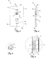
- Figure 1 is an exploded perspective view of one embodiment of the invention.
- Figures 2 is an exploded cross-sectional side view of the invention depicted in Figure 1 taken along line 2-2.
- Figure 3 is a top assembled view of the invention depicted in Figure 1 .
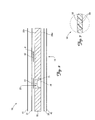
- Figure 4 is a cross-sectional side view of the invention depicted in Figure 3 taken along line 3-3.
- Figure 5 is an enlarged cross-sectional detailed side view of a portion of the invention depicted in Figure 4 encompassing the second or 0% mass of photoluminescent composition and associated battery.
- Figure 6 is an enlarged top view of a portion of the invention depicted in Figure 4 encompassing the second or 0% mass of photoluminescent composition and associated battery.
- Figure 7 is a microscopically enlarged cross-sectional side view of one embodiment of a photoluminescent composition suitable for use as the first and second masses of photoluminescent composition in the present invention.
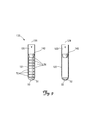
- Figure 8 is a side view of another embodiment of the invention.
- Figure 9 is a cross-sectional side view of the invention depicted in Figure 8 .
- Figure 10 is a grossly enlarged cross-sectional side view of the closed end of the invention depicted in Figure 9 .
- metal-air battery means an electrochemical battery or fuel cell powered by oxidizing a metal, such as cadmium, lead, lithium or zinc, with ambient oxygen, typically air.
- activated metal-air battery means a metal-air battery with air access hole(s) to the cathode are open to the environment (i.e., the oxygen barrier film typically placed over the air access hole(s) has been removed to permit air to enter the cell).
- oxygen impermeable means a material that when formed into a 1 mil (25.4 ⁇ m) film has an oxygen transmission rate of less than 100 c 3 /m 2 day when measured in accordance with ASTM F 1927.
- oxygen barrier means a film, including coated, metalized and multiple layer films, that are impervious to oxygen (such as a layer of metal) or have an oxygen transmission rate of less than 20 c 3 /m 2 day when measured in accordance with ASTM F 1927.
- oxygen sensitivity or "sensitivity to oxygen” means sensitivity measured by luminescence quenching.
- thin film means a film having a thickness of less than 10 ⁇ m.
- small container means a container will a fillable volume of less than 20 ml.
- a first embodiment of a first aspect of the invention is a calibration card 10 for use in calibrating an analytical instrument (not shown) for reading photoluminescent sensors or probes (not shown).
- the calibration card 10 includes first 51 and second 52 masses of an oxygen sensitive photoluminescent composition 50.
- the first mass of oxygen sensitive photoluminescent composition 51 is isolated from the surrounding environment and in fluid communication with an oxygen consuming zinc-air battery 70 for scavenging oxygen from the hermetically sealed first mass 51.
- the second mass of oxygen sensitive photoluminescent composition 52 is in fluid communication with the surrounding environment for exposing the second mass 52 to an environmental concentration of oxygen.
- the first mass 51 (also referenced as the 0% mass for convenience) and the second mass 52 (also referenced as the 21 % mass for convenience) each comprise an oxygen-sensitive photoluminescent dye 59 that is the same as the oxygen-sensitive photoluminescent dye employed in the probes (not shown) read by the instrument (not shown), embedded within an oxygen permeable carrier matrix 58 that is the same as the carrier matrix employed in the probes (not shown) read by the instrument (not shown).
- FIGS 1 and 2 depict the constructional components of one embodiment of a calibration card 10 in accordance with this invention.
- the calibration card 10 depicted in Figures 1 and 2 includes laterally spaced first and second masses of oxygen sensitive photoluminescent composition 51 and 52 (collectively referenced as photoluminescent masses 50) mounted onto a first major surface 20v of an intermediate spacer layer 20 and sandwiched between an upper cover layer 41 and a lower base layer 42.
- the spacer layer 20, upper cover layer 41, and lower base layer 42 are all effective as an oxygen barrier.
- the first mass of oxygen sensitive photoluminescent composition 51 is in fluid communication with an activated metal-air battery 70 retained within a retention well 29 within the spacer layer 20.
- the second mass of oxygen sensitive photoluminescent composition 52 is placed in fluid communication with the surrounding environment via a channel 19 through the spacer layer 20 and lower base layer 42.
- Adhesive layers 31 and 32 secure the upper cover layer 41 and lower base layer 42 to the upper major surface 20v and lower major surface 20w of the spacer layer 20, respectively, thereby sandwiching the first and second photoluminescent masses 50 between the oxygen barrier upper cover layer 41 and lower base layer 42.
- the calibration card 10 has a top edge 10a, a bottom edge 10b, a right side edge 10r, a left side edge 10s, an upper major surface 10v and a lower major surface 10w.
- the card 10 should have a length of about 4 to 20 cm, a width of about 4 to 20 cm, and a thickness of less than 1 cm. A card 10 smaller than this is prone to being lost or misplaced while a card 10 larger than this becomes unnecessarily bulky.
- the card 10 preferably has a length of about 6 to 10 cm, a width of about 4 to 8 cm, and a thickness of about 0.5 to 1 cm, and most preferably approximates the length and width of a standard credit card (i.e., about 8.5 cm long and 5.5 cm wide).
- the card 10 should be durable and wear resistant.
- the intermediate spacer layer 20 contributes the bulk of the structural integrity to the card 10 and provides the thickness necessary to accommodate the metal-air battery 70.
- the spacer layer 20 may be transparent, translucent or opaque as desired.
- the spacer layer 20 should be relatively impermeable to O 2 for purposes of limiting the rate at which O 2 can permeate through the edges (10a, 10b, 10r and 10s) of the card 10 and into contact with the first mass of oxygen sensitive photoluminescent composition 51.
- Suitable materials include specifically, but not exclusively, plastics such as an acrylic or polyethylene terephthalate; and metals such as aluminum, copper or steel.
- the cover layer 41 provides some additional structural integrity to the card 10 and serves as a protective covering for the photoluminescent masses 50.
- the cover layer 41 needs to be transparent or translucent at least at the specific wavelengths at which the photoluminescent masses 50 absorb and emit energy.
- the cover layer 41 serves as an oxygen barrier for reducing the rate at which oxygen permeates through the card 10 and into contact with the first mass of oxygen sensitive photoluminescent composition 51.
- Suitable materials include specifically, but not exclusively, plastics. Preferred plastics are mylar and polyethylene terephthalate.
- the base layer 42 also provides some additional structural integrity to the card 10.
- the base layer 42 need not be transparent or translucent as the photoluminescent masses 50 are not interrogated through the base layer 42.
- the base layer 42, as with the cover layer 41, serves as an oxygen barrier for reducing the rate at which oxygen permeates through the card 10 and into contact with the first mass of oxygen sensitive photoluminescent composition 51.
- Suitable materials include specifically, but not exclusively, plastics. Preferred plastics are mylar and polyethylene terephthalate.
- Adhesive layers 31 and 32 may be selected from a wide variety of adhesives suitable for use in laminating metal and plastic layers together, including various hot melt and pressure-sensitive adhesives. It may also be possible to forgo the use of the adhesive layer when the cover layer 41 and base layer 42 are capable of being bound directly to the intermediate spacer layer 20 such as by heat welding.
- the oxygen sensitive photoluminescent masses 50 include an oxygen-sensitive photoluminescent dye 59 embedded within an oxygen-permeable carrier matrix 58.
- the same oxygen sensitive photoluminescent masses 50 are used for both the 0% and the 21% masses 51 and 52, and need to match the photoluminescent masses 50 used in the sensors or probes (not shown) that are read by the analytical instrument (not shown) being calibrated. Most preferably, the oxygen sensitive photoluminescent masses 50 and the probes (not shown) that are intended to be read by the instrument (not shown) are produced in the same run from the same batch of photoluminescent composition.
- the oxygen-sensitive photoluminescent dye 59 may be selected from any of the well-known oxygen sensitive photoluminescent dyes used in the construction of oxygen sensitive photoluminescent probes (not shown).
- a nonexhaustive list of such oxygen sensitive photoluminescent dyes 59 includes specifically, but not exclusively, ruthenium(II)-bipyridyl and ruthenium(II)-diphenylphenanothroline complexes, porphyrin-ketones such as platinum(II)-octaethylporphine-ketone, platinum(II)-porphyrin such as platinum(II)-tetrakis(pentafluorophenyl)porphine, palladium(II)-porphyrin such as palladium(II)-tetrakis(pentafluorophenyl)porphine, phosphorescent metallocomplexes of tetrabenzoporphyrins, chlor
- the oxygen-sensitive photoluminescent dye 59 is compounded with a suitable carrier matrix 58.
- Compositions used as the carrier matrix 58 are oxygen-permeable compositions, preferably highly oxygen permeable compositions.
- One of routine skill in the art is capable of selecting such oxygen-permeable carrier compositions 58.
- a nonexhaustive list of polymers suitable for use as the carrier matrix 58 includes specifically, but not exclusively, silicone, polystryrene, polycarbonate, polysulfone, and some other polymers and co-polymers.
- the oxygen sensitive photoluminescent masses 50 are coated onto a support layer (not shown).
- the support layer is typically a sheet or film formed from a material that is compatible with the oxygen sensitive photoluminescent masses 50.
- One of routine skill in the art is capable of selecting suitable support layer.
- An activated metal-air battery 70 is retained within a retention well 29 in the intermediate spacer layer 20 and in fluid communication with the 0% oxygen sensitive photoluminescent mass 51 for consuming oxygen from around the hermetically sealed 0% oxygen sensitive photoluminescent mass 51.
- Metal-air batteries such as a zinc-air battery, are different from most other batteries in that they "breath" oxygen from the air for use as the cathode reactant.
- the electrochemical system can be more formally defined as zinc/potassium hydroxide/oxygen, but "zinc-air” is the widely used common name.
- Metal-air batteries are commercially available from a variety of sources, including The Gillette Company under the brand name Duracell®.
- a typical zinc-air cell consists of a zinc anode, an aqueous alkaline electrolyte and an air cathode. Power is derived from the reduction of oxygen at the cathode, and the oxidation of zinc at the anode. The simplified net reaction is shown below: 2Zn + O 2 ⁇ 2ZnO
- the anode in a zinc air cell is typically powdered zinc amalgam.
- the zinc powder typically contains a very low level of mercury to prevent internal pressure buildup due to hydrogen evolution from the self-discharge of the zinc in the electrolyte.
- a gelling agent is also usually mixed with the zinc amalgam to maintain the uniformity of the zinc powder-electrolyte mixture during discharge.
- the zinc in the anode is oxidized to form zinc hydroxide in the form of the soluble zincate [Zn(OH) 4 2- ] ion.
- the half reaction for the anode is shown below: Zn + 40H- - ⁇ Zn(OH) 4 2- + 2e -
- the zinc hydroxide accumulates around the zinc particle, but does not impede either ionic or particle-to-particle conductance until the zinc is fully oxidized. As the discharge proceeds, the zincate ions eventually precipitate to form zinc oxide (ZnO). Zn(OH) 4 2- ⁇ ZnO + H 2 O + 2OH -
- the air cathode in a zinc-air cell is typically a mixture of carbon, Teflon, and a small amount of manganese dioxide impressed onto a nickel-plated screen. This material is then laminated with a Teflon layer on one side and a separating membrane on the other.
- the Teflon layer allows gases, most importantly oxygen, to diffuse into and out of the cell, and also provides resistance to leakage.
- the separator acts as an ion conductor between the electrodes and as an insulator to prevent internal short-circuiting.
- Atmospheric oxygen reacts with catalysts in the air electrode and electrolyte to produce hydroxide ions.
- the half reaction for the air cathode is shown below: O 2 + 2H 2 O + 4e - ⁇ 4OH -
- the alkaline electrolyte typically employed in a zinc air cell is an aqueous solution of potassium hydroxide with a small amount of zinc oxide to prevent self-discharge of the anode.
- Potassium hydroxide provides good ionic conductance between the anode and cathode to permit efficient discharge of the cell.
- the anode subassembly includes the anode can and the insulator.
- An exemplary anode can which holds the zinc anode, is a tri-clad material comprised of a copper interior lining for good chemical compatibility, a stainless steel layer in the middle for strength, and nickel layer on the outside for good electrical contact. A nylon insulator surrounds this can and insulates the negative terminal from the positive terminal. A sealant coating is typically applied to the insulator prior to its assembly with the anode can.
- the cathode subassembly consists of the cathode can and the air electrode.
- An exemplary cathode can is made of nickel plated steel, and contains multiple air holes punched into the bottom to provide air access to the cathode. These air holes provide the pathway for oxygen to enter the cell.
- a porous membrane is typically placed directly over the holes to facilitate uniform air distribution across the air electrode.
- a loose layer of Teflon is typically provided on top of this membrane to help form the cathode seal.
- the air electrode itself i.e. cathode
- the air electrode itself is oriented with its Teflon side toward the air holes.
- the zinc-anode mix and the electrolyte are dispensed into the anode subassembly, over which the cathode subassembly is placed and sealed.
- a tab is placed over the air holes and attached via a mild adhesive to seal the cell and prevent environmental oxygen from entering the cell and contacting the cathode.
- the cell is activated by simply peeling off the tab.
- the activated battery 70 must have an oxygen consumption rate that exceeds the permeation rate of oxygen into the sealed space containing the first mass of photoluminescent composition 51 from the surrounding air.
- An activated battery 70 that consumes oxygen at a rate that is less than the permeation rate of oxygen into the sealed space containing the first mass of photoluminescent composition 51 will result in an inaccurate calibration as the first mass of photoluminescent composition 51 will be exposed to an oxygen concentration well in excess of 0%.
- an activated battery 70 that consumes oxygen at a rate that is significantly greater than the permeation rate of oxygen into the sealed space containing the first mass of photoluminescent composition 51 will cause the card 10 to structurally deform due to an internal pressure buildup caused by hydrogen evolution from a continuous and prolonged operation in an oxygen starved environment.
- the activated battery 70 preferably consumes oxygen at a rate that is only slightly greater than the permeation rate of oxygen into the sealed space containing the first mass of photoluminescent composition 51, with a generally acceptable range of between two to ten times the permeation rate of oxygen into the sealed space.
- a suitable load 71 may be operably connected to the battery 70.
- a load 71 having a resistance of at least 100,000 ⁇ , preferably at least 500,000 ⁇ , and most preferably at least 1,000,000 ⁇ will provide the necessary and desired rate of oxygen consumption.
- the upper major surface 10v of the card 10 is imprinted with first indicia 61 and second indicia 62 (collectively indicia 60) for identifying the first photoluminescent mass 51 as the mass representative of a probe (not shown) exposed to limited oxygen (e.g ., 0%, Zero, Low, Minimum, etc.), and identifying the second photoluminescent mass 52 as the mass representative of a probe (not shown) exposed to an environmental concentration of oxygen (e.g., 21%, Twenty One, High, Maximum, Atmosphere, etc.).
- limited oxygen e.g 0%, Zero, Low, Minimum, etc.
- an environmental concentration of oxygen e.g., 21%, Twenty One, High, Maximum, Atmosphere, etc.
- the lifespan of the calibration card 10 is dictated by the effective life of the metal-air battery 70 employed in the card 10, which will typically be between one and three years from activation of the battery 70.
- a second embodiment of a first aspect of the invention is a calibration set 100 for use in calibrating an analytical instrument (not shown) for reading photoluminescent sensors or probes (not shown).
- the calibration set 100 includes first 51 and second 52 masses of an oxygen sensitive photoluminescent composition 50 retained within separate containers or vials 120.
- the first mass of oxygen sensitive photoluminescent composition 51 is retained within the well 129 of a first container or vial 121, isolated from the surrounding environment by a stopper 140 or other suitable sealing device, and in fluid communication with at least one oxygen consuming zinc-air battery 70 for scavenging oxygen from the hermetically sealed first mass 51.
- the second mass of oxygen sensitive photoluminescent composition 52 is similarly retained within the well 129 of a second container or vial 122 and isolated from the surrounding environment by a stopper 140 or other suitable sealing device.
- the well 129 of the second container or vial 122 does not include an oxygen consuming zinc-air battery, but rather is filled with air containing an environmental concentration of oxygen ( i.e., 20.98%) so that the second mass of oxygen sensitive photoluminescent composition 52 is and remains in fluid communication with an environmental concentration of oxygen.
- the second mass of oxygen sensitive photoluminescent composition 52 is preferably placed in fluid communication with the surrounding environment via a channel 149 through the stopper 140.
- the containers or vials 120 each have an open top end 120a and a closed bottom end 120b.
- the containers or vials 120 preferably have a fillable volume of less than 50 ml, with a preference for small containers having a fillable volume of between 2 and 20 ml.
- each container or vial 120 is coated with a mass of oxygen sensitive photoluminescent composition 50.
- the bottom 120b of the containers or vials 120 can be coated with oxygen sensitive photoluminescent composition 50 by depositing the composition 50 into the container or vial 120 in liquid form and allowed to dry.
- the containers or vials 120 can be constructed from substantially any material possessing the necessary structural integrity.
- the containers or vials 120 need to be transparent or translucent at least at the specific wavelengths at which the photoluminescent masses 50 absorb and emit energy.
- the first container or vial 121 also serves as an oxygen barrier for reducing the rate at which oxygen permeates through the container or vial 121 and into contact with the first mass of oxygen sensitive photoluminescent composition 51.
- the first 121 and second 122 containers or vials are preferably identical to one another. Suitable materials include specifically, but not exclusively, glass and certain plastics. Glass is preferred.
- the containers or vials 120 in the calibration set 10 are preferably selected to match the size, shape, composition and configuration of the test containers or vials read or interrogated by the analytical instrument being calibrated. This is of particular value when the instrument is customized to handle and read specific containers or vials (e.g., designed to transport and read 5 ml Epindorf vials).
- the stopper 140 is preferably selected to provide an excellent seal against the sidewall of the container or vial 120 and serve as an oxygen barrier.
- the stopper 140 need not be transparent or translucent at least at the specific wavelengths at which the photoluminescent masses 50 absorb and emit energy as interrogation of the oxygen sensitive photoluminescent composition 50 is intended to be taken through the bottom 120b of the containers or vials 120.
- Suitable materials for use as a stopper 140 include specifically, but not exclusively, rubber, cork, rigid insert fitted with an o-ring seal, etc. Generally, rubber is preferred as they are inexpensive and readily available.
- first indicia 61 and second indicia 62 are imprinted with first indicia 61 and second indicia 62 (collectively indicia 60) for identifying the first photoluminescent mass 51 as the mass representative of a probe (not shown) exposed to limited oxygen (e.g., 0%, Zero, Low, Minimum, etc.), and identifying the second photoluminescent mass 52 as the mass representative of a probe (not shown) exposed to an environmental concentration of oxygen (e.g., 21%, Twenty One, High, Maximum, Atmosphere, etc.).
- limited oxygen e.g., 0%, Zero, Low, Minimum, etc.
- an environmental concentration of oxygen e.g., 21%, Twenty One, High, Maximum, Atmosphere, etc.
- the lifespan of the calibration set 100 is dictated by the effective life of the metal-air battery 70 in the containers or vials 120.
- the lifespan can be enhanced by employing more than one battery 70.
- the size and/or number of batteries 70 is preferably selected to ensure a lifespan of at least one year from activation of the battery 70.
- the calibration card 10 and the calibration set 100 can be used to quickly and easily calibrate an optical oxygen sensor (not shown) having a calibration mode.
- calibration of an optical oxygen sensor simply involves the steps of (1) setting the optical sensor to calibration mode, and (2) sequentially taking an oxygen concentration reading from each of the masses of oxygen sensitive photoluminescent composition 51 and 52 such that the oxygen concentration reading is correlated with the known oxygen concentration to which the mass of oxygen sensitive photoluminescent composition 51 and 52 is exposed.
- Correlation of the oxygen concentration reading to the oxygen sensitive photoluminescent composition 51 or 52 from which the reading was taken can be accomplished in various ways.
- One technique is to take the oxygen concentration readings in a predetermined sequence previously input into the optical oxygen sensor (not shown).
- a second technique is to automatically provide the optical oxygen sensor (not shown) with additional data each time a reading is taken effective for indicating which of the masses of oxygen sensitive photoluminescent composition 51 and 52 was sensed (e.g., a unique bar code provided next to each mass 50 that is read each time a mass 50 is read).
- Yet a third technique is to provide the optical oxygen sensor (not shown) with additional data each time a reading is taken effective for indicating the oxygen concentration to which the sensed mass of oxygen sensitive photoluminescent composition 51 and 52 was exposed at the time of the reading (e.g., user input of 0 after the 0% mass 51 is read and user input of 21 after the 21% mass 52 is read).
- both the oxygen probes (not shown) and the calibration card 10 or calibration set 100 operate in photoluminescence lifetime mode.
- Luminescence lifetime measurements can be performed by any of the known methods, including specifically but not exclusively direct measurement of luminescence decay, measurement of luminescence phase shift, anisotropy, or any other parameter which is related directly or indirectly to the luminescence lifetime of the probe and the first and second masses 51 and 52.
Landscapes
- Health & Medical Sciences (AREA)
- Physics & Mathematics (AREA)
- Life Sciences & Earth Sciences (AREA)
- Chemical & Material Sciences (AREA)
- Immunology (AREA)
- Pathology (AREA)
- Analytical Chemistry (AREA)
- Biochemistry (AREA)
- General Health & Medical Sciences (AREA)
- General Physics & Mathematics (AREA)
- Engineering & Computer Science (AREA)
- Chemical Kinetics & Catalysis (AREA)
- Molecular Biology (AREA)
- General Chemical & Material Sciences (AREA)
- Theoretical Computer Science (AREA)
- Mathematical Physics (AREA)
- Spectroscopy & Molecular Physics (AREA)
- Nuclear Medicine, Radiotherapy & Molecular Imaging (AREA)
- Manufacturing & Machinery (AREA)
- Electrochemistry (AREA)
- Optics & Photonics (AREA)
- Sustainable Development (AREA)
- Sustainable Energy (AREA)
- Emergency Medicine (AREA)
- Dispersion Chemistry (AREA)
- Biophysics (AREA)
- Investigating Or Analysing Materials By The Use Of Chemical Reactions (AREA)
- Investigating, Analyzing Materials By Fluorescence Or Luminescence (AREA)
Applications Claiming Priority (1)
| Application Number | Priority Date | Filing Date | Title |
|---|---|---|---|
| US13/112,123 US8323978B2 (en) | 2008-11-07 | 2011-05-20 | Calibration system and technique for photoluminescent oxygen sensors with zero point maintained with a metal-air battery |
Publications (2)
| Publication Number | Publication Date |
|---|---|
| EP2525221A1 true EP2525221A1 (de) | 2012-11-21 |
| EP2525221B1 EP2525221B1 (de) | 2018-08-08 |
Family
ID=46125182
Family Applications (1)
| Application Number | Title | Priority Date | Filing Date |
|---|---|---|---|
| EP12166808.1A Not-in-force EP2525221B1 (de) | 2011-05-20 | 2012-05-04 | Kalibriersystem und -technik für photolumineszente Sauerstoffsensoren mit einem durch eine Metall-Luft-Batterie aufrechterhaltenen Nullpunkt |
Country Status (3)
| Country | Link |
|---|---|
| EP (1) | EP2525221B1 (de) |
| JP (1) | JP2012242391A (de) |
| CN (1) | CN102788773A (de) |
Cited By (1)
| Publication number | Priority date | Publication date | Assignee | Title |
|---|---|---|---|---|
| WO2017125483A1 (de) * | 2016-01-20 | 2017-07-27 | Gea Food Solutions Germany Gmbh | Verfahren zum kalibrieren eines sensors zum auslesen einer gaskonzentrationsindikatorsubstanz einer verpackung |
Families Citing this family (5)
| Publication number | Priority date | Publication date | Assignee | Title |
|---|---|---|---|---|
| US9057687B2 (en) * | 2012-04-20 | 2015-06-16 | Mocon, Inc. | Calibration vial and technique for calibrating a fiber optic oxygen sensing needle |
| JP6029008B2 (ja) * | 2013-02-04 | 2016-11-24 | エイブル株式会社 | 酸素濃度測定用センサーの製造方法 |
| CN106918574B (zh) * | 2015-12-25 | 2019-11-12 | 楚天科技股份有限公司 | 一种残氧量检测机器人的残氧量检测校正方法 |
| CN106501130B (zh) * | 2016-10-18 | 2019-08-16 | 西安理工大学 | 一种有机涂层扩散系数测试装置及基于该装置的测试方法 |
| CN114923541B (zh) * | 2022-05-17 | 2024-08-27 | 吉林大学 | 基于光响应智能金属空气电池的水位报警器 |
Citations (9)
| Publication number | Priority date | Publication date | Assignee | Title |
|---|---|---|---|---|
| WO1990004268A1 (en) * | 1988-10-13 | 1990-04-19 | The Secretary Of State For Defence In Her Britannic Majesty's Government Of The United Kingdom Of Great Britain And Northern Ireland | Apparatus to provide oxygen-free gas |
| US5371016A (en) * | 1993-04-26 | 1994-12-06 | Becton, Dickinson And Company | Detecting biological activities in culture vials |
| EP0697460A2 (de) * | 1994-08-15 | 1996-02-21 | Becton, Dickinson and Company | Optischer Blutkultursensor |
| US6060196A (en) * | 1995-10-06 | 2000-05-09 | Ceramtec, Inc. | Storage-stable zinc anode based electrochemical cell |
| US20090029402A1 (en) * | 2005-04-15 | 2009-01-29 | Dmitri Boris Papkovsky | Assessment of Biological or Chemical Samples |
| WO2010053888A1 (en) * | 2008-11-07 | 2010-05-14 | Mocon, Inc | Calibration card for oxygen optical sensors |
| US7740965B2 (en) * | 2003-08-01 | 2010-06-22 | The Gillette Company | Battery |
| US20110154881A1 (en) * | 2008-11-07 | 2011-06-30 | Ascheman Timothy A | Calibration card for photoluminescent oxygen sensors with zero point maintained with a metal-air battery |
| US20110223678A1 (en) * | 2008-11-07 | 2011-09-15 | Ascheman Timothy A | Calibration system and technique for photoluminescent oxygen sensors with zero point maintained with a metal-air battery |
Family Cites Families (7)
| Publication number | Priority date | Publication date | Assignee | Title |
|---|---|---|---|---|
| JPS54136577A (en) * | 1978-04-17 | 1979-10-23 | Japan Storage Battery Co Ltd | Method of decreasing oxygen concentration of mixture gas containing oxygen |
| JPS5535927A (en) * | 1978-09-05 | 1980-03-13 | Japan Storage Battery Co Ltd | Operating battery-type deoxidized member |
| US4810655A (en) * | 1985-07-03 | 1989-03-07 | Abbott Laboratories | Method for measuring oxygen concentration |
| US6171368B1 (en) * | 1998-11-06 | 2001-01-09 | Med-E-Cell | Gas extraction from closed containers |
| AU2002256413B2 (en) * | 2001-05-04 | 2007-06-07 | Sensors For Medicine And Science, Inc. | Electro-optical sensing device with reference channel |
| JP2005195354A (ja) * | 2003-12-26 | 2005-07-21 | Toyota Motor Corp | 酸素濃度測定装置および方法 |
| US20070224495A1 (en) * | 2006-03-22 | 2007-09-27 | Gibbons Daniel W | Zinc/air cell |
-
2012
- 2012-05-04 EP EP12166808.1A patent/EP2525221B1/de not_active Not-in-force
- 2012-05-15 CN CN2012101496999A patent/CN102788773A/zh active Pending
- 2012-05-15 JP JP2012111283A patent/JP2012242391A/ja active Pending
Patent Citations (9)
| Publication number | Priority date | Publication date | Assignee | Title |
|---|---|---|---|---|
| WO1990004268A1 (en) * | 1988-10-13 | 1990-04-19 | The Secretary Of State For Defence In Her Britannic Majesty's Government Of The United Kingdom Of Great Britain And Northern Ireland | Apparatus to provide oxygen-free gas |
| US5371016A (en) * | 1993-04-26 | 1994-12-06 | Becton, Dickinson And Company | Detecting biological activities in culture vials |
| EP0697460A2 (de) * | 1994-08-15 | 1996-02-21 | Becton, Dickinson and Company | Optischer Blutkultursensor |
| US6060196A (en) * | 1995-10-06 | 2000-05-09 | Ceramtec, Inc. | Storage-stable zinc anode based electrochemical cell |
| US7740965B2 (en) * | 2003-08-01 | 2010-06-22 | The Gillette Company | Battery |
| US20090029402A1 (en) * | 2005-04-15 | 2009-01-29 | Dmitri Boris Papkovsky | Assessment of Biological or Chemical Samples |
| WO2010053888A1 (en) * | 2008-11-07 | 2010-05-14 | Mocon, Inc | Calibration card for oxygen optical sensors |
| US20110154881A1 (en) * | 2008-11-07 | 2011-06-30 | Ascheman Timothy A | Calibration card for photoluminescent oxygen sensors with zero point maintained with a metal-air battery |
| US20110223678A1 (en) * | 2008-11-07 | 2011-09-15 | Ascheman Timothy A | Calibration system and technique for photoluminescent oxygen sensors with zero point maintained with a metal-air battery |
Cited By (2)
| Publication number | Priority date | Publication date | Assignee | Title |
|---|---|---|---|---|
| WO2017125483A1 (de) * | 2016-01-20 | 2017-07-27 | Gea Food Solutions Germany Gmbh | Verfahren zum kalibrieren eines sensors zum auslesen einer gaskonzentrationsindikatorsubstanz einer verpackung |
| US10836521B2 (en) | 2016-01-20 | 2020-11-17 | Gea Food Solutions Weert B.V. | Flow wrapper with leakage-control of the resulting packages |
Also Published As
| Publication number | Publication date |
|---|---|
| EP2525221B1 (de) | 2018-08-08 |
| CN102788773A (zh) | 2012-11-21 |
| JP2012242391A (ja) | 2012-12-10 |
Similar Documents
| Publication | Publication Date | Title |
|---|---|---|
| EP2455744B1 (de) | Kalibrierkarte für photolumineszente Sauerstoffsensoren mit einem durch eine Metall-Luft-Batterie aufrechterhaltenen Nullpunkt | |
| US8323978B2 (en) | Calibration system and technique for photoluminescent oxygen sensors with zero point maintained with a metal-air battery | |
| EP2525221B1 (de) | Kalibriersystem und -technik für photolumineszente Sauerstoffsensoren mit einem durch eine Metall-Luft-Batterie aufrechterhaltenen Nullpunkt | |
| CN102265136B (zh) | 用于光学氧传感器的校准卡 | |
| US12007357B2 (en) | Electrochemical sensor | |
| US20150107993A1 (en) | Methods and apparatuses for evaluating water pollution | |
| JP2008249696A (ja) | 乾式光−化学二酸化炭素センサー | |
| US9915602B2 (en) | Calibration vial and technique for calibrating a fiber optic oxygen sensing needle | |
| US6423209B1 (en) | Acid gas measuring sensors and method of using same | |
| AU2013369643A1 (en) | An electrochemical sensor for sensing nitrous oxide | |
| EP2348310A2 (de) | Elektrodenvorkonditionierung | |
| CN113316716B (zh) | 用于伏安检测的系统和方法 | |
| Chebil et al. | based metal-air battery electrochemical sensor for smartphone-assisted oxygen monitoring in food packaging | |
| JP2008116452A (ja) | 電子発光モジュールを有する分析用試験片 | |
| US4999265A (en) | Alkaline cells containing fluorescent dyes | |
| WO2013075736A1 (en) | Device and method for rapid assay of multiple biological samples for oxygen consumption | |
| CN118302894A (zh) | 带有安全设备的电池蓄存器和用于触发安全设备的方法 | |
| WO2002099410A9 (en) | Sensor device and method for indicating oxygen consumption | |
| US10338049B2 (en) | Electrochemical method and device for determining the content of DOC and/or TOC and/or IC in an aqueous sample | |
| Neethirajan | Development of a Polyaniline Boronic Acid (PABA) Carbon Dioxide (CO2) Sensor for Use in the Agri-food Industry | |
| HK1124119A (en) | Dry optical-chemical carbon dioxide sensor | |
| CZ30650U1 (cs) | Elektrochemická cela pro analýzu obsahu polutantů v kapalině |
Legal Events
| Date | Code | Title | Description |
|---|---|---|---|
| PUAI | Public reference made under article 153(3) epc to a published international application that has entered the european phase |
Free format text: ORIGINAL CODE: 0009012 |
|
| AK | Designated contracting states |
Kind code of ref document: A1 Designated state(s): AL AT BE BG CH CY CZ DE DK EE ES FI FR GB GR HR HU IE IS IT LI LT LU LV MC MK MT NL NO PL PT RO RS SE SI SK SM TR |
|
| AX | Request for extension of the european patent |
Extension state: BA ME |
|
| 17P | Request for examination filed |
Effective date: 20130521 |
|
| RIC1 | Information provided on ipc code assigned before grant |
Ipc: H01M 8/04089 20160101ALI20171123BHEP Ipc: G01N 21/27 20060101AFI20171123BHEP Ipc: G01N 21/64 20060101ALI20171123BHEP Ipc: G01N 31/22 20060101ALI20171123BHEP Ipc: H01M 12/06 20060101ALI20171123BHEP Ipc: G01N 21/77 20060101ALN20171123BHEP |
|
| GRAP | Despatch of communication of intention to grant a patent |
Free format text: ORIGINAL CODE: EPIDOSNIGR1 |
|
| RIC1 | Information provided on ipc code assigned before grant |
Ipc: G01N 21/77 20060101ALN20171130BHEP Ipc: G01N 31/22 20060101ALI20171130BHEP Ipc: H01M 12/06 20060101ALI20171130BHEP Ipc: G01N 21/27 20060101AFI20171130BHEP Ipc: G01N 21/64 20060101ALI20171130BHEP Ipc: H01M 8/04089 20160101ALI20171130BHEP |
|
| STAA | Information on the status of an ep patent application or granted ep patent |
Free format text: STATUS: GRANT OF PATENT IS INTENDED |
|
| INTG | Intention to grant announced |
Effective date: 20180104 |
|
| GRAJ | Information related to disapproval of communication of intention to grant by the applicant or resumption of examination proceedings by the epo deleted |
Free format text: ORIGINAL CODE: EPIDOSDIGR1 |
|
| STAA | Information on the status of an ep patent application or granted ep patent |
Free format text: STATUS: REQUEST FOR EXAMINATION WAS MADE |
|
| REG | Reference to a national code |
Ref country code: DE Ref legal event code: R079 Ref document number: 602012049357 Country of ref document: DE Free format text: PREVIOUS MAIN CLASS: G01N0031220000 Ipc: G01N0021270000 |
|
| GRAS | Grant fee paid |
Free format text: ORIGINAL CODE: EPIDOSNIGR3 |
|
| STAA | Information on the status of an ep patent application or granted ep patent |
Free format text: STATUS: GRANT OF PATENT IS INTENDED |
|
| GRAP | Despatch of communication of intention to grant a patent |
Free format text: ORIGINAL CODE: EPIDOSNIGR1 |
|
| INTC | Intention to grant announced (deleted) | ||
| RIC1 | Information provided on ipc code assigned before grant |
Ipc: G01N 21/64 20060101ALI20180517BHEP Ipc: H01M 12/06 20060101ALI20180517BHEP Ipc: G01N 21/27 20060101AFI20180517BHEP Ipc: G01N 21/77 20060101ALN20180517BHEP Ipc: G01N 31/22 20060101ALI20180517BHEP Ipc: H01M 8/04089 20160101ALI20180517BHEP |
|
| INTG | Intention to grant announced |
Effective date: 20180605 |
|
| GRAA | (expected) grant |
Free format text: ORIGINAL CODE: 0009210 |
|
| STAA | Information on the status of an ep patent application or granted ep patent |
Free format text: STATUS: THE PATENT HAS BEEN GRANTED |
|
| AK | Designated contracting states |
Kind code of ref document: B1 Designated state(s): AL AT BE BG CH CY CZ DE DK EE ES FI FR GB GR HR HU IE IS IT LI LT LU LV MC MK MT NL NO PL PT RO RS SE SI SK SM TR |
|
| REG | Reference to a national code |
Ref country code: GB Ref legal event code: FG4D |
|
| REG | Reference to a national code |
Ref country code: CH Ref legal event code: EP Ref country code: AT Ref legal event code: REF Ref document number: 1027580 Country of ref document: AT Kind code of ref document: T Effective date: 20180815 |
|
| REG | Reference to a national code |
Ref country code: IE Ref legal event code: FG4D |
|
| REG | Reference to a national code |
Ref country code: DE Ref legal event code: R096 Ref document number: 602012049357 Country of ref document: DE |
|
| REG | Reference to a national code |
Ref country code: NL Ref legal event code: MP Effective date: 20180808 |
|
| REG | Reference to a national code |
Ref country code: LT Ref legal event code: MG4D |
|
| REG | Reference to a national code |
Ref country code: AT Ref legal event code: MK05 Ref document number: 1027580 Country of ref document: AT Kind code of ref document: T Effective date: 20180808 |
|
| PG25 | Lapsed in a contracting state [announced via postgrant information from national office to epo] |
Ref country code: GR Free format text: LAPSE BECAUSE OF FAILURE TO SUBMIT A TRANSLATION OF THE DESCRIPTION OR TO PAY THE FEE WITHIN THE PRESCRIBED TIME-LIMIT Effective date: 20181109 Ref country code: NO Free format text: LAPSE BECAUSE OF FAILURE TO SUBMIT A TRANSLATION OF THE DESCRIPTION OR TO PAY THE FEE WITHIN THE PRESCRIBED TIME-LIMIT Effective date: 20181108 Ref country code: SE Free format text: LAPSE BECAUSE OF FAILURE TO SUBMIT A TRANSLATION OF THE DESCRIPTION OR TO PAY THE FEE WITHIN THE PRESCRIBED TIME-LIMIT Effective date: 20180808 Ref country code: BG Free format text: LAPSE BECAUSE OF FAILURE TO SUBMIT A TRANSLATION OF THE DESCRIPTION OR TO PAY THE FEE WITHIN THE PRESCRIBED TIME-LIMIT Effective date: 20181108 Ref country code: NL Free format text: LAPSE BECAUSE OF FAILURE TO SUBMIT A TRANSLATION OF THE DESCRIPTION OR TO PAY THE FEE WITHIN THE PRESCRIBED TIME-LIMIT Effective date: 20180808 Ref country code: IS Free format text: LAPSE BECAUSE OF FAILURE TO SUBMIT A TRANSLATION OF THE DESCRIPTION OR TO PAY THE FEE WITHIN THE PRESCRIBED TIME-LIMIT Effective date: 20181208 Ref country code: RS Free format text: LAPSE BECAUSE OF FAILURE TO SUBMIT A TRANSLATION OF THE DESCRIPTION OR TO PAY THE FEE WITHIN THE PRESCRIBED TIME-LIMIT Effective date: 20180808 Ref country code: AT Free format text: LAPSE BECAUSE OF FAILURE TO SUBMIT A TRANSLATION OF THE DESCRIPTION OR TO PAY THE FEE WITHIN THE PRESCRIBED TIME-LIMIT Effective date: 20180808 Ref country code: FI Free format text: LAPSE BECAUSE OF FAILURE TO SUBMIT A TRANSLATION OF THE DESCRIPTION OR TO PAY THE FEE WITHIN THE PRESCRIBED TIME-LIMIT Effective date: 20180808 Ref country code: LT Free format text: LAPSE BECAUSE OF FAILURE TO SUBMIT A TRANSLATION OF THE DESCRIPTION OR TO PAY THE FEE WITHIN THE PRESCRIBED TIME-LIMIT Effective date: 20180808 Ref country code: PL Free format text: LAPSE BECAUSE OF FAILURE TO SUBMIT A TRANSLATION OF THE DESCRIPTION OR TO PAY THE FEE WITHIN THE PRESCRIBED TIME-LIMIT Effective date: 20180808 |
|
| REG | Reference to a national code |
Ref country code: CH Ref legal event code: PK Free format text: BERICHTIGUNGEN |
|
| RIC2 | Information provided on ipc code assigned after grant |
Ipc: G01N 31/22 20060101ALI20180517BHEP Ipc: H01M 12/06 20060101ALI20180517BHEP Ipc: G01N 21/77 20060101ALN20180517BHEP Ipc: H01M 8/04089 20160101ALI20180517BHEP Ipc: G01N 21/64 20060101ALI20180517BHEP Ipc: G01N 21/27 20060101AFI20180517BHEP |
|
| PG25 | Lapsed in a contracting state [announced via postgrant information from national office to epo] |
Ref country code: AL Free format text: LAPSE BECAUSE OF FAILURE TO SUBMIT A TRANSLATION OF THE DESCRIPTION OR TO PAY THE FEE WITHIN THE PRESCRIBED TIME-LIMIT Effective date: 20180808 Ref country code: LV Free format text: LAPSE BECAUSE OF FAILURE TO SUBMIT A TRANSLATION OF THE DESCRIPTION OR TO PAY THE FEE WITHIN THE PRESCRIBED TIME-LIMIT Effective date: 20180808 Ref country code: HR Free format text: LAPSE BECAUSE OF FAILURE TO SUBMIT A TRANSLATION OF THE DESCRIPTION OR TO PAY THE FEE WITHIN THE PRESCRIBED TIME-LIMIT Effective date: 20180808 |
|
| PG25 | Lapsed in a contracting state [announced via postgrant information from national office to epo] |
Ref country code: EE Free format text: LAPSE BECAUSE OF FAILURE TO SUBMIT A TRANSLATION OF THE DESCRIPTION OR TO PAY THE FEE WITHIN THE PRESCRIBED TIME-LIMIT Effective date: 20180808 Ref country code: ES Free format text: LAPSE BECAUSE OF FAILURE TO SUBMIT A TRANSLATION OF THE DESCRIPTION OR TO PAY THE FEE WITHIN THE PRESCRIBED TIME-LIMIT Effective date: 20180808 Ref country code: CZ Free format text: LAPSE BECAUSE OF FAILURE TO SUBMIT A TRANSLATION OF THE DESCRIPTION OR TO PAY THE FEE WITHIN THE PRESCRIBED TIME-LIMIT Effective date: 20180808 Ref country code: IT Free format text: LAPSE BECAUSE OF FAILURE TO SUBMIT A TRANSLATION OF THE DESCRIPTION OR TO PAY THE FEE WITHIN THE PRESCRIBED TIME-LIMIT Effective date: 20180808 Ref country code: RO Free format text: LAPSE BECAUSE OF FAILURE TO SUBMIT A TRANSLATION OF THE DESCRIPTION OR TO PAY THE FEE WITHIN THE PRESCRIBED TIME-LIMIT Effective date: 20180808 |
|
| REG | Reference to a national code |
Ref country code: DE Ref legal event code: R097 Ref document number: 602012049357 Country of ref document: DE |
|
| PG25 | Lapsed in a contracting state [announced via postgrant information from national office to epo] |
Ref country code: SK Free format text: LAPSE BECAUSE OF FAILURE TO SUBMIT A TRANSLATION OF THE DESCRIPTION OR TO PAY THE FEE WITHIN THE PRESCRIBED TIME-LIMIT Effective date: 20180808 Ref country code: SM Free format text: LAPSE BECAUSE OF FAILURE TO SUBMIT A TRANSLATION OF THE DESCRIPTION OR TO PAY THE FEE WITHIN THE PRESCRIBED TIME-LIMIT Effective date: 20180808 Ref country code: DK Free format text: LAPSE BECAUSE OF FAILURE TO SUBMIT A TRANSLATION OF THE DESCRIPTION OR TO PAY THE FEE WITHIN THE PRESCRIBED TIME-LIMIT Effective date: 20180808 |
|
| PLBE | No opposition filed within time limit |
Free format text: ORIGINAL CODE: 0009261 |
|
| STAA | Information on the status of an ep patent application or granted ep patent |
Free format text: STATUS: NO OPPOSITION FILED WITHIN TIME LIMIT |
|
| 26N | No opposition filed |
Effective date: 20190509 |
|
| PG25 | Lapsed in a contracting state [announced via postgrant information from national office to epo] |
Ref country code: SI Free format text: LAPSE BECAUSE OF FAILURE TO SUBMIT A TRANSLATION OF THE DESCRIPTION OR TO PAY THE FEE WITHIN THE PRESCRIBED TIME-LIMIT Effective date: 20180808 |
|
| REG | Reference to a national code |
Ref country code: CH Ref legal event code: PL |
|
| PG25 | Lapsed in a contracting state [announced via postgrant information from national office to epo] |
Ref country code: LI Free format text: LAPSE BECAUSE OF NON-PAYMENT OF DUE FEES Effective date: 20190531 Ref country code: CH Free format text: LAPSE BECAUSE OF NON-PAYMENT OF DUE FEES Effective date: 20190531 Ref country code: MC Free format text: LAPSE BECAUSE OF FAILURE TO SUBMIT A TRANSLATION OF THE DESCRIPTION OR TO PAY THE FEE WITHIN THE PRESCRIBED TIME-LIMIT Effective date: 20180808 |
|
| REG | Reference to a national code |
Ref country code: BE Ref legal event code: MM Effective date: 20190531 |
|
| PG25 | Lapsed in a contracting state [announced via postgrant information from national office to epo] |
Ref country code: LU Free format text: LAPSE BECAUSE OF NON-PAYMENT OF DUE FEES Effective date: 20190504 |
|
| PG25 | Lapsed in a contracting state [announced via postgrant information from national office to epo] |
Ref country code: TR Free format text: LAPSE BECAUSE OF FAILURE TO SUBMIT A TRANSLATION OF THE DESCRIPTION OR TO PAY THE FEE WITHIN THE PRESCRIBED TIME-LIMIT Effective date: 20180808 |
|
| PG25 | Lapsed in a contracting state [announced via postgrant information from national office to epo] |
Ref country code: IE Free format text: LAPSE BECAUSE OF NON-PAYMENT OF DUE FEES Effective date: 20190504 |
|
| PG25 | Lapsed in a contracting state [announced via postgrant information from national office to epo] |
Ref country code: BE Free format text: LAPSE BECAUSE OF NON-PAYMENT OF DUE FEES Effective date: 20190531 |
|
| PG25 | Lapsed in a contracting state [announced via postgrant information from national office to epo] |
Ref country code: PT Free format text: LAPSE BECAUSE OF FAILURE TO SUBMIT A TRANSLATION OF THE DESCRIPTION OR TO PAY THE FEE WITHIN THE PRESCRIBED TIME-LIMIT Effective date: 20181208 |
|
| PG25 | Lapsed in a contracting state [announced via postgrant information from national office to epo] |
Ref country code: CY Free format text: LAPSE BECAUSE OF FAILURE TO SUBMIT A TRANSLATION OF THE DESCRIPTION OR TO PAY THE FEE WITHIN THE PRESCRIBED TIME-LIMIT Effective date: 20180808 |
|
| PG25 | Lapsed in a contracting state [announced via postgrant information from national office to epo] |
Ref country code: MT Free format text: LAPSE BECAUSE OF FAILURE TO SUBMIT A TRANSLATION OF THE DESCRIPTION OR TO PAY THE FEE WITHIN THE PRESCRIBED TIME-LIMIT Effective date: 20180808 Ref country code: HU Free format text: LAPSE BECAUSE OF FAILURE TO SUBMIT A TRANSLATION OF THE DESCRIPTION OR TO PAY THE FEE WITHIN THE PRESCRIBED TIME-LIMIT; INVALID AB INITIO Effective date: 20120504 |
|
| PG25 | Lapsed in a contracting state [announced via postgrant information from national office to epo] |
Ref country code: MK Free format text: LAPSE BECAUSE OF FAILURE TO SUBMIT A TRANSLATION OF THE DESCRIPTION OR TO PAY THE FEE WITHIN THE PRESCRIBED TIME-LIMIT Effective date: 20180808 |
|
| PGFP | Annual fee paid to national office [announced via postgrant information from national office to epo] |
Ref country code: GB Payment date: 20220523 Year of fee payment: 11 Ref country code: FR Payment date: 20220520 Year of fee payment: 11 Ref country code: DE Payment date: 20220531 Year of fee payment: 11 |
|
| P01 | Opt-out of the competence of the unified patent court (upc) registered |
Effective date: 20230526 |
|
| REG | Reference to a national code |
Ref country code: DE Ref legal event code: R119 Ref document number: 602012049357 Country of ref document: DE |
|
| GBPC | Gb: european patent ceased through non-payment of renewal fee |
Effective date: 20230504 |
|
| PG25 | Lapsed in a contracting state [announced via postgrant information from national office to epo] |
Ref country code: DE Free format text: LAPSE BECAUSE OF NON-PAYMENT OF DUE FEES Effective date: 20231201 Ref country code: GB Free format text: LAPSE BECAUSE OF NON-PAYMENT OF DUE FEES Effective date: 20230504 |
|
| PG25 | Lapsed in a contracting state [announced via postgrant information from national office to epo] |
Ref country code: FR Free format text: LAPSE BECAUSE OF NON-PAYMENT OF DUE FEES Effective date: 20230531 |