EP2525231A1 - Dispositif et procédé de surveillance d'un processus de dosage de liquide dans des pipettes à piston élévateur - Google Patents
Dispositif et procédé de surveillance d'un processus de dosage de liquide dans des pipettes à piston élévateur Download PDFInfo
- Publication number
- EP2525231A1 EP2525231A1 EP11168004A EP11168004A EP2525231A1 EP 2525231 A1 EP2525231 A1 EP 2525231A1 EP 11168004 A EP11168004 A EP 11168004A EP 11168004 A EP11168004 A EP 11168004A EP 2525231 A1 EP2525231 A1 EP 2525231A1
- Authority
- EP
- European Patent Office
- Prior art keywords
- pipette
- pipette tip
- neck
- actuator
- volume
- Prior art date
- Legal status (The legal status is an assumption and is not a legal conclusion. Google has not performed a legal analysis and makes no representation as to the accuracy of the status listed.)
- Withdrawn
Links
- 239000007788 liquid Substances 0.000 title claims abstract description 44
- 238000000034 method Methods 0.000 title claims abstract description 22
- 238000012544 monitoring process Methods 0.000 title description 5
- 230000008859 change Effects 0.000 claims abstract description 24
- 238000007654 immersion Methods 0.000 claims abstract description 14
- 230000005284 excitation Effects 0.000 claims abstract description 7
- 239000006260 foam Substances 0.000 claims description 7
- 238000007598 dipping method Methods 0.000 claims description 3
- 238000001514 detection method Methods 0.000 claims description 2
- 230000000630 rising effect Effects 0.000 claims description 2
- 230000008901 benefit Effects 0.000 description 4
- 238000013461 design Methods 0.000 description 4
- 239000012528 membrane Substances 0.000 description 4
- 230000001419 dependent effect Effects 0.000 description 3
- 230000000694 effects Effects 0.000 description 3
- 238000005259 measurement Methods 0.000 description 3
- 230000008569 process Effects 0.000 description 3
- 230000005520 electrodynamics Effects 0.000 description 2
- 239000000126 substance Substances 0.000 description 2
- 241001136792 Alle Species 0.000 description 1
- 239000006096 absorbing agent Substances 0.000 description 1
- TZCXTZWJZNENPQ-UHFFFAOYSA-L barium sulfate Chemical compound [Ba+2].[O-]S([O-])(=O)=O TZCXTZWJZNENPQ-UHFFFAOYSA-L 0.000 description 1
- 230000008878 coupling Effects 0.000 description 1
- 238000010168 coupling process Methods 0.000 description 1
- 238000005859 coupling reaction Methods 0.000 description 1
- 230000002950 deficient Effects 0.000 description 1
- 238000009795 derivation Methods 0.000 description 1
- 238000005265 energy consumption Methods 0.000 description 1
- 230000007613 environmental effect Effects 0.000 description 1
- 238000011156 evaluation Methods 0.000 description 1
- 238000005187 foaming Methods 0.000 description 1
- 239000011521 glass Substances 0.000 description 1
- 230000002706 hydrostatic effect Effects 0.000 description 1
- 230000010354 integration Effects 0.000 description 1
- 239000000463 material Substances 0.000 description 1
- 239000000203 mixture Substances 0.000 description 1
- 230000010355 oscillation Effects 0.000 description 1
- 230000000704 physical effect Effects 0.000 description 1
- 230000007704 transition Effects 0.000 description 1
Images


Classifications
-
- G—PHYSICS
- G01—MEASURING; TESTING
- G01N—INVESTIGATING OR ANALYSING MATERIALS BY DETERMINING THEIR CHEMICAL OR PHYSICAL PROPERTIES
- G01N35/00—Automatic analysis not limited to methods or materials provided for in any single one of groups G01N1/00 - G01N33/00; Handling materials therefor
- G01N35/10—Devices for transferring samples or any liquids to, in, or from, the analysis apparatus, e.g. suction devices, injection devices
- G01N35/1009—Characterised by arrangements for controlling the aspiration or dispense of liquids
-
- B—PERFORMING OPERATIONS; TRANSPORTING
- B01—PHYSICAL OR CHEMICAL PROCESSES OR APPARATUS IN GENERAL
- B01L—CHEMICAL OR PHYSICAL LABORATORY APPARATUS FOR GENERAL USE
- B01L3/00—Containers or dishes for laboratory use, e.g. laboratory glassware; Droppers
- B01L3/02—Burettes; Pipettes
- B01L3/021—Pipettes, i.e. with only one conduit for withdrawing and redistributing liquids
- B01L3/0217—Pipettes, i.e. with only one conduit for withdrawing and redistributing liquids of the plunger pump type
- B01L3/0237—Details of electronic control, e.g. relating to user interface
-
- G—PHYSICS
- G01—MEASURING; TESTING
- G01F—MEASURING VOLUME, VOLUME FLOW, MASS FLOW OR LIQUID LEVEL; METERING BY VOLUME
- G01F23/00—Indicating or measuring liquid level or level of fluent solid material, e.g. indicating in terms of volume or indicating by means of an alarm
- G01F23/22—Indicating or measuring liquid level or level of fluent solid material, e.g. indicating in terms of volume or indicating by means of an alarm by measuring physical variables, other than linear dimensions, pressure or weight, dependent on the level to be measured, e.g. by difference of heat transfer of steam or water
- G01F23/28—Indicating or measuring liquid level or level of fluent solid material, e.g. indicating in terms of volume or indicating by means of an alarm by measuring physical variables, other than linear dimensions, pressure or weight, dependent on the level to be measured, e.g. by difference of heat transfer of steam or water by measuring the variations of parameters of electromagnetic or acoustic waves applied directly to the liquid or fluent solid material
- G01F23/296—Acoustic waves
- G01F23/2966—Acoustic waves making use of acoustical resonance or standing waves
-
- G—PHYSICS
- G01—MEASURING; TESTING
- G01N—INVESTIGATING OR ANALYSING MATERIALS BY DETERMINING THEIR CHEMICAL OR PHYSICAL PROPERTIES
- G01N35/00—Automatic analysis not limited to methods or materials provided for in any single one of groups G01N1/00 - G01N33/00; Handling materials therefor
- G01N35/10—Devices for transferring samples or any liquids to, in, or from, the analysis apparatus, e.g. suction devices, injection devices
- G01N35/1009—Characterised by arrangements for controlling the aspiration or dispense of liquids
- G01N35/1016—Control of the volume dispensed or introduced
-
- B—PERFORMING OPERATIONS; TRANSPORTING
- B01—PHYSICAL OR CHEMICAL PROCESSES OR APPARATUS IN GENERAL
- B01L—CHEMICAL OR PHYSICAL LABORATORY APPARATUS FOR GENERAL USE
- B01L2200/00—Solutions for specific problems relating to chemical or physical laboratory apparatus
- B01L2200/14—Process control and prevention of errors
- B01L2200/143—Quality control, feedback systems
-
- B—PERFORMING OPERATIONS; TRANSPORTING
- B01—PHYSICAL OR CHEMICAL PROCESSES OR APPARATUS IN GENERAL
- B01L—CHEMICAL OR PHYSICAL LABORATORY APPARATUS FOR GENERAL USE
- B01L2400/00—Moving or stopping fluids
- B01L2400/04—Moving fluids with specific forces or mechanical means
- B01L2400/0403—Moving fluids with specific forces or mechanical means specific forces
- B01L2400/0433—Moving fluids with specific forces or mechanical means specific forces vibrational forces
Definitions
- the invention relates to a device and a method for monitoring a liquid metering process in Kolbenhubpipetten and a pipette tip for such a device and such a method.
- the dependent claims 2 to 8 relate to further advantageous Embodiments.
- the object is further achieved with a method for operating a Kolbenhubpipette having the features of claim 9.
- the dependent claims 10 to 12 relate to further advantageous method steps.
- the object is further achieved by the use of pipette tips according to claim 13.
- the present invention relates to the field of electronic measurements of physical and geometric quantities, e.g. Volume, density, degree of filling and density. Also, a wide range of conditions can be measured. It is an integration of sensors, evaluation electronics and actuators.
- the material composition and the geometry of the control system can be arbitrary and adapted to the physical or geometric variables to be converted.
- An object of the present invention is to reduce as much as possible with a device for Kolbenhubpipetten today occur error effects during pipetting or eliminate completely. In particular, today it is almost impossible to distinguish whether the immersion tip is immersed purely in the liquid to be pipetted, or whether it is still in the foam on the surface.
- the inventive device also has the advantage that it is possible by the use of miniaturized electrical components and mechanical components, the required device, in particular the actuator and optionally the sensor to make so small that they can be integrated into the pipetting or can be installed in the piston stroke pipette, which gives the additional advantage with respect to the inventive device that the number Kolbenhubpipetten per area can be increased considerably.
- the monitoring pressure sensors used today require considerable space.
- the device according to the invention for a piston-stroke pipette makes use of the physical properties of a Helmholtz resonator. Therefore, it is necessary that the Kolbenhubpipette and the pipette tip are designed and arranged mutually adapted so that they form a Helmholtz resonator.
- the pipette tip is designed as part of a Helmholtz resonator in that the pipette tip has a neck-shaped section with a pipette neck length L, and in that the neck-shaped section opens into a pipette tip opening with a cross-sectional area A.
- the pipette tip and the piston stroke pipette enclose a common volume V.
- a Helmholtz resonator has a pronounced resonant frequency or resonant circuit frequency, wherein the resonant frequency depends inter alia on the cross-sectional area A and the volume V. Closing the cross-sectional area A during immersion of the pipette tip results in a sudden change in the self-resonance. A change in the volume V also results in a change of the self-resonance, so that it is possible to detect the immersion of the pipette tip into a liquid or to detect a pipetting volume by determining the change of the self-resonance.
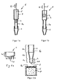
- Fig. 8 schematically shows a view of a Helmholtz resonator 13 with a hollow body 13c with volume V, a neck-shaped Section 13a with a length L and an opening 13b with a cross-sectional area A.
- a Helmholtz resonator is an absorber which, due to its resonant behavior, deprives the sound field located outside the Helmholtz resonator of energy. Due to the elasticity of the air volume in the interior of the hollow body in combination with the inertial mass of the air located in the neck-shaped section, a mechanical mass-spring system with a pronounced natural resonance arises.
- a Helmholtz resonator 13 for monitoring a Liquid metering operation is suitable in Kolbenhubpipetten when the Kolbenhubpipette and the pipette tip are formed such that they together form a Helmholtz resonator 13, and when an actuator is used, which stimulates the volume V in the Helmholtz resonator 13 to vibrate.
- FIGS. 2a and 2b each show in a longitudinal section an embodiment of a pipette tip 2 comprising a first Section 2a and a neck-shaped portion 2c, which has a length L and opens into a pipette tip opening 2d with a cross-sectional area A.
- the neck-shaped portion 2c is configured as a hollow cylinder.
- the neck-shaped portion 2c can be configured in a variety of ways, and could also be curved, for example, or have an angular inner cross-section, for example a quadrangular one Have internal cross section.
- FIG. 2a illustrated pipette tip 2 also includes a conical transition section 2b.
- the interior of the pipette tips 2 forms a first partial volume V 1 .
- FIG. 3 shows in a longitudinal section a Kolbenhubpipette 1, which consists essentially of two parts, a pipette housing 3 with it in the direction K displaceably mounted piston 4 with piston rod 5 and a separate pipette tip 2, which is designed similar to that already in FIG. 2b shown.
- the interior of the piston stroke pipette 1 forms a second partial volume V 2 .
- the pipette tip 2 can, as in FIG. 4a shown, are attached to the pipette housing 3, and is preferably detachably connected to the pipette housing 3, preferably such that there is a fluid-tight connection between the pipette tip 2 and the pipette housing 3.
- the pipette tip 2 and the piston stroke pipette 1 thus surround a common volume V, wherein a Helmholtz resonator 13 is formed together with the pipette tip 2, with a neck-shaped portion 2c of length L and an outlet opening 2d with cross-sectional area A.
- the piston stroke pipette 1 could also be so be configured such that the pipette housing 3 is firmly and permanently connected to the pipette tip 2, wherein the pipette housing 3 and the pipette tip 2 could also consist of a single part together and are made for example of glass or a plastic.
- a vibration actuator actuator 9 to generate in the common volume V a vibration or a sound wave.
- the Actuator 9 is designed outside cylindrical and is located on the pipette housing 3 at.
- the actuator 9 is internally conically widening towards the bottom.
- a sensor 10 is also arranged, which is designed annular and rests against the inner edge of the pipette housing 3.
- the actuator 9 and the sensor 10 are connected via electrical lines 11a to a drive device 11.
- a so-called vibration exciter 9 is mounted, which acts both on the side and in the pipe design on the volume V.
- the vibrator 9 can be combined as shown in a cone-shaped design with the volume V, which also allows to measure the hydrostatic back pressure of the rising liquid.
- the inventive control system for Kolbenhubpipettierungen provides in this way for the first time information about the exact immersion in the actual liquid, even if there is an undefined surface with it befindlichem foam.
- FIG. 4a the pipetting arrangement is shown with the individual components. In such a configuration, consisting of the volume V, the neck L and the opening A of the pipette tip 2d, one can apply a physical relationship not yet used for reciprocating pipettes.
- ⁇ c ⁇ A V ⁇ L
- the piston 4 acts on the volume V and changes the angular frequency and so a volume change or the amount to be pipetted can be detected by the change of the angular frequency when the pipette tip area A and the length of the pipette tip neck L are constant. This is given by the design of the pipette tips.
- Another possibility is to determine the precise immersion of the tip in the liquid, since the immersion of the pipette tip in the liquid, the surface A is changed and generates a jump change in the angular frequency. If the pipette tip dives only in foam, then there is only a small change in the angular frequency.
- position of the pipette 1 shown corresponds to the value ⁇ of the resonance angular frequency ( ⁇ 0) of the Helmholtz resonator 13.
- the actuation device 11 and the actuator 9 are designed such that this change in the angular frequency ⁇ can be measured so that the immersion of the pipette opening 2d into the liquid can be measured accurately. This detuning can be measured with different arrangements.
- the drive device 11 measures the reactance of the actuator 9, so that no sensor 10 is required for the measurement. If the actuator 9 is operated at an angular frequency ⁇ , which corresponds to the resonant circuit frequency ⁇ 0 of the Helmholtz resonator 13, relatively little energy is required for its operation.
- the actuator 9 Before and during immersion of the pipette tip 2 in the liquid 7, the actuator 9 is excited at the angular frequency ⁇ , wherein the resonant circuit frequency ⁇ 0 of the Helmholtz resonator 13 changes abruptly when immersed, so that between the actuator 9 exciting angular frequency ⁇ and the Resonant circuit frequency ⁇ 0 of the Helmholtz resonator 13 results in a frequency detuning, which increases the reactance of the actuator 9.
- This change in the reactance and / or the frequency change can be measured by the drive device 11, for example, in which the energy consumption of the actuator 9 or the oscillation path of the actuator 9 is measured.
- angular frequency ⁇ with which the actuator 9 is excited to readjust by a delta omega ⁇ in such a way that the actuator 9 after dipping the Pipette tip oscillates again with the resonance frequency ⁇ 0 of the Helmholtz resonator 13.
- the resulting difference or the Deltaomega ⁇ is thus a measure of the state change.
- the inventive method has the further advantage that it can be distinguished whether the pipette tip opening 2 d is immersed in a liquid 7, or, as in FIG. 2b shown in a substance located above the liquid level 7a, such as a foam 8.
- a liquid 7a such as a foam 8.
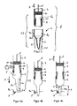
- the FIG. 5 shows in a longitudinal section an embodiment of an actuator 9.
- the actuator 9 comprises a housing 9d, a cavity 9c, a movable diaphragm 9a and a membrane 9a driving piezoelectric, electrodynamic or capacitive driver 9b.
- the diaphragm 9a transmits the vibration, similar to a speaker, due to the movement A in the volume V of the piston stroke pipette 1.
- the driver 9b is fed via an electrical line 11a.
- the reactance can be measured with the aid of the driver 9b.
- FIG. 6 shows in a longitudinal section schematically a sensor 10 with a housing 10a and a membrane 10b.
- an opening 3b is also arranged, which opens into the outer space of the piston stroke pipette 1, so that the membrane 10b separates the volume V from the outside space.
- the diaphragm 10b includes a sensor for measuring the vibration of the diaphragm 10b.
- FIG 7a shows in a longitudinal section through the pipette housing 3, a further embodiment of an actuator 9.
- This actuator 9 is designed similar to a speaker and includes an elastic membrane 9a, which is movably mounted in a recess of the pipette housing 3 in the direction of movement A.
- a coil housing with coil 9d disposed therein is fixedly connected to the diaphragm 9a.
- a preferably circular disk-shaped permanent magnet 9e is arranged, which has a passage opening 9g in the center, and which has an annular projecting magnetic part 9f.
- the coil 9d and the magnetic part 9f together form an electrodynamic driver 9b.
- the magnet part 9f is spaced apart from the coil 9d and surrounds the coil 9d from the outside, so that the coil 9d is in a permanent magnetic field.
- a cavity 9 c is formed between the coil 9 d and the magnet part 9 f, wherein the cavity 9 c is fluid-conductively connected to the environment outside the piston-lifting pipette 1 via the passage opening 9 g.
- the coil 9d may comprise a single coil which is electrically connected to the drive device 11 and which serves to excite the diaphragm 9a.
- the coil 9d comprises two separate coils, wherein the first coil as described above for excitation and to drive the diaphragm 9a is used, and wherein the second coil serves as a sensor to the reactance and / or movement of the diaphragm 9a measure up.
- the first and the second coil are connected via electrical lines 11a to the drive device 11, not shown.
- FIG. 7b shows a plan view of the actuator 9 from the outside, or a plan view of the circular disc-shaped permanent magnet 9e, which has the passage opening 9g in the center.
- the device according to the invention and the method according to the invention make it possible for the pipetting volume located in the piston-stroke pipette 1 or the volume of the in Figure 4c to measure the amount of liquid 7b shown.
- an arrangement is preferably selected as in the FIGS. 6 and 7 illustrated, which have an opening 3b or 9g, so that in addition to the pipette tip opening 2d via the openings 3b or 9g an additional coupling of the volume V with the area outside the Kolbenhubpipette 1 consists.
- FIG. 3 shown suitable.
- the amount of liquid 7b located in the neck-shaped section 2c results in the length L of the air located in the neck-shaped section 2c being reduced to the length L ', which results in a change in the resonance frequency ⁇ 0 .
- the amount of liquid 7b which increases progressively as the liquid is drawn up, results in a change in the resonant circuit frequency ⁇ 0 , which can be measured via the drive device 11, for example by the drive device 11 constantly adjusting the frequency of the actuator 9 in such a way that it adjusts itself is in resonance or approximately in resonance with respect to the volume V.
- the resonant properties of a Kolbenhubpipette be detected in advance by different amounts of liquid 7b are absorbed into the Kolbenhubpipette, and the respective resonant frequency is measured, so that a relationship between the volume of the liquid amount 7b and the resonant frequency dependent thereon can be measured and stored.
- the volume of liquid amount 7b present in the piston-stroke pipette can then be closed in each case via the resonant frequency measured at the piston-stroke pipette.
Landscapes
- Physics & Mathematics (AREA)
- General Physics & Mathematics (AREA)
- Chemical & Material Sciences (AREA)
- Health & Medical Sciences (AREA)
- Electromagnetism (AREA)
- Acoustics & Sound (AREA)
- Fluid Mechanics (AREA)
- Life Sciences & Earth Sciences (AREA)
- Analytical Chemistry (AREA)
- Biochemistry (AREA)
- General Health & Medical Sciences (AREA)
- Thermal Sciences (AREA)
- Immunology (AREA)
- Pathology (AREA)
- Chemical Kinetics & Catalysis (AREA)
- Engineering & Computer Science (AREA)
- Human Computer Interaction (AREA)
- Clinical Laboratory Science (AREA)
- Devices For Use In Laboratory Experiments (AREA)
- Sampling And Sample Adjustment (AREA)
Priority Applications (1)
| Application Number | Priority Date | Filing Date | Title |
|---|---|---|---|
| PCT/EP2012/059214 WO2012156492A1 (fr) | 2011-05-16 | 2012-05-16 | Dispositif et procédé destinés à surveiller un processus de dosage d'un liquide dans des pipettes à piston |
Applications Claiming Priority (1)
| Application Number | Priority Date | Filing Date | Title |
|---|---|---|---|
| CH8192011 | 2011-05-16 |
Publications (1)
| Publication Number | Publication Date |
|---|---|
| EP2525231A1 true EP2525231A1 (fr) | 2012-11-21 |
Family
ID=44484851
Family Applications (1)
| Application Number | Title | Priority Date | Filing Date |
|---|---|---|---|
| EP11168004A Withdrawn EP2525231A1 (fr) | 2011-05-16 | 2011-05-28 | Dispositif et procédé de surveillance d'un processus de dosage de liquide dans des pipettes à piston élévateur |
Country Status (2)
| Country | Link |
|---|---|
| EP (1) | EP2525231A1 (fr) |
| WO (1) | WO2012156492A1 (fr) |
Cited By (2)
| Publication number | Priority date | Publication date | Assignee | Title |
|---|---|---|---|---|
| GB2506883A (en) * | 2012-10-10 | 2014-04-16 | Stratec Biomedical Ag | A method and a detector for detecting size and type of a pipetting tip |
| CN114303043A (zh) * | 2019-07-02 | 2022-04-08 | 中尺度技术有限责任公司 | 基于声音确定液体分配器中液体接触和液体体积的装置和方法 |
Citations (3)
| Publication number | Priority date | Publication date | Assignee | Title |
|---|---|---|---|---|
| US4846003A (en) * | 1988-06-08 | 1989-07-11 | Beckman Instruments, Inc. | Acoustic impedance system for pipette tip detection |
| DE10148608A1 (de) | 2001-03-09 | 2002-09-12 | Hamilton Bonaduz Ag Bonaduz | Verfahren und Vorrichtung zur Beurteilung eines Flüssigkeitsdosierungsvorgangs |
| JP2010008298A (ja) * | 2008-06-30 | 2010-01-14 | Hitachi High-Technologies Corp | 分注装置 |
Family Cites Families (2)
| Publication number | Priority date | Publication date | Assignee | Title |
|---|---|---|---|---|
| JP2008232829A (ja) * | 2007-03-20 | 2008-10-02 | Hitachi High-Technologies Corp | 分注用ノズルチップ |
| JP5129729B2 (ja) * | 2008-02-08 | 2013-01-30 | 富士フイルム株式会社 | ピペットチップ |
-
2011
- 2011-05-28 EP EP11168004A patent/EP2525231A1/fr not_active Withdrawn
-
2012
- 2012-05-16 WO PCT/EP2012/059214 patent/WO2012156492A1/fr not_active Ceased
Patent Citations (3)
| Publication number | Priority date | Publication date | Assignee | Title |
|---|---|---|---|---|
| US4846003A (en) * | 1988-06-08 | 1989-07-11 | Beckman Instruments, Inc. | Acoustic impedance system for pipette tip detection |
| DE10148608A1 (de) | 2001-03-09 | 2002-09-12 | Hamilton Bonaduz Ag Bonaduz | Verfahren und Vorrichtung zur Beurteilung eines Flüssigkeitsdosierungsvorgangs |
| JP2010008298A (ja) * | 2008-06-30 | 2010-01-14 | Hitachi High-Technologies Corp | 分注装置 |
Cited By (3)
| Publication number | Priority date | Publication date | Assignee | Title |
|---|---|---|---|---|
| GB2506883A (en) * | 2012-10-10 | 2014-04-16 | Stratec Biomedical Ag | A method and a detector for detecting size and type of a pipetting tip |
| GB2506883B (en) * | 2012-10-10 | 2018-07-11 | Stratec Biomedical Ag | Device and method for detecting size and type of a pipetting tip |
| CN114303043A (zh) * | 2019-07-02 | 2022-04-08 | 中尺度技术有限责任公司 | 基于声音确定液体分配器中液体接触和液体体积的装置和方法 |
Also Published As
| Publication number | Publication date |
|---|---|
| WO2012156492A1 (fr) | 2012-11-22 |
Similar Documents
| Publication | Publication Date | Title |
|---|---|---|
| EP3877732B1 (fr) | Multicapteur vibronique | |
| EP2247927B1 (fr) | Procédé permettant de contrôler l'état d'une pipette, procédé de pipettage, dispositif de pipettage, et tube d'aspiration pour dispositif de pipettage | |
| EP1544596B1 (fr) | Méthode et appareil de détermination de la viscosité | |
| DE2119802A1 (de) | Densitometer und Durchflußmengen überwachungseinrichtung und zugehöriges Verfahren | |
| DE1171646B (de) | Vorrichtung zum Bestimmen physikalischer Stoffeigenschaften | |
| EP3006916B1 (fr) | Procédé et dispositif destinés à la détermination de la qualité de remplissage d'un résonateur de flexions | |
| DE102010040600A1 (de) | Verfahren zum Detektieren einer Verstopfung in einem Coriolis-Durchflussmessgerät | |
| DE102015122542A1 (de) | Feldgerät der Prozessmesstechnik | |
| DE102020204687A1 (de) | Automatische Verifizierung und Re-Kalibrierung eines Pumpenfördervolumens | |
| DE102015100573A1 (de) | Verfahren zum Betreiben eines Coriolis-Massedurchflussmessgeräts | |
| AT516281B1 (de) | Verfahren zur Ermittlung des Befüllungsgrads eines Schwingerrohrs eines Biegeschwingers und Biegeschwinger | |
| EP1881316A2 (fr) | Méthode et dispositif pour déterminer la densité d'un fluide | |
| DE102018206078B4 (de) | Dosiersystem und Verfahren zur Dosierung einer vorgebbaren Flüssigkeitsmenge | |
| EP3314210B1 (fr) | Appareil émetteur de champs doté d'un circuit de compensation pour l'élimination des impacts environnementaux | |
| EP2525231A1 (fr) | Dispositif et procédé de surveillance d'un processus de dosage de liquide dans des pipettes à piston élévateur | |
| DE2528575C3 (fr) | ||
| DE102010003733B4 (de) | Verfahren zur Detektion von Gasblasen in einem flüssigen Medium | |
| DE102007019186A1 (de) | Pipetiergerät nebst Verfahren | |
| DE102020127757A1 (de) | Sensor und Verfahren zur Bestimmung einer Prozessgröße eines Mediums | |
| DE2144770C2 (de) | Einrichtung zum Bestimmen physikalischer Eigenschaften von gasförmigen, flüssigen oder pulverförmigen Stoffen | |
| DE102010001229A1 (de) | Verfahren und Vorrichtung zur Bestimmung eines flüssigkeitsspezifischen oder vom Benetzungszustand einer Pipettierspitze abhängigen Parameters durch Schwingungsanregung | |
| EP2707680B1 (fr) | Procede d'ajustement de la quantite d'un liquide a doser dans un embout d'une pipette par detection de vibrations et dispositif pour executer le procede | |
| DE102010003734A1 (de) | Verfahren zur Detektion von Gasblasen in einem flüssigen Medium | |
| EP3605029B1 (fr) | Procédé de détermination d'un état de commutation d'un capteur d'impédance et capteur d'impédance | |
| DE10003094A1 (de) | Verfahren und Vorrichtung zum berührungslosen Bestimmen von Füllungseigenschaften eines Gefäßes |
Legal Events
| Date | Code | Title | Description |
|---|---|---|---|
| PUAI | Public reference made under article 153(3) epc to a published international application that has entered the european phase |
Free format text: ORIGINAL CODE: 0009012 |
|
| AK | Designated contracting states |
Kind code of ref document: A1 Designated state(s): AL AT BE BG CH CY CZ DE DK EE ES FI FR GB GR HR HU IE IS IT LI LT LU LV MC MK MT NL NO PL PT RO RS SE SI SK SM TR |
|
| AX | Request for extension of the european patent |
Extension state: BA ME |
|
| STAA | Information on the status of an ep patent application or granted ep patent |
Free format text: STATUS: THE APPLICATION IS DEEMED TO BE WITHDRAWN |
|
| 18D | Application deemed to be withdrawn |
Effective date: 20130522 |