EP2525240A2 - Système pour mesurer un décalage temporel et procédé de mesure d'un décalage temporel - Google Patents
Système pour mesurer un décalage temporel et procédé de mesure d'un décalage temporel Download PDFInfo
- Publication number
- EP2525240A2 EP2525240A2 EP12275069A EP12275069A EP2525240A2 EP 2525240 A2 EP2525240 A2 EP 2525240A2 EP 12275069 A EP12275069 A EP 12275069A EP 12275069 A EP12275069 A EP 12275069A EP 2525240 A2 EP2525240 A2 EP 2525240A2
- Authority
- EP
- European Patent Office
- Prior art keywords
- time
- sensor node
- acoustic
- signal
- vessel
- Prior art date
- Legal status (The legal status is an assumption and is not a legal conclusion. Google has not performed a legal analysis and makes no representation as to the accuracy of the status listed.)
- Granted
Links
Images




Classifications
-
- G—PHYSICS
- G01—MEASURING; TESTING
- G01V—GEOPHYSICS; GRAVITATIONAL MEASUREMENTS; DETECTING MASSES OR OBJECTS; TAGS
- G01V1/00—Seismology; Seismic or acoustic prospecting or detecting
- G01V1/22—Transmitting seismic signals to recording or processing apparatus
-
- G—PHYSICS
- G01—MEASURING; TESTING
- G01V—GEOPHYSICS; GRAVITATIONAL MEASUREMENTS; DETECTING MASSES OR OBJECTS; TAGS
- G01V1/00—Seismology; Seismic or acoustic prospecting or detecting
- G01V1/38—Seismology; Seismic or acoustic prospecting or detecting specially adapted for water-covered areas
-
- G—PHYSICS
- G01—MEASURING; TESTING
- G01V—GEOPHYSICS; GRAVITATIONAL MEASUREMENTS; DETECTING MASSES OR OBJECTS; TAGS
- G01V1/00—Seismology; Seismic or acoustic prospecting or detecting
- G01V1/38—Seismology; Seismic or acoustic prospecting or detecting specially adapted for water-covered areas
- G01V1/3861—Seismology; Seismic or acoustic prospecting or detecting specially adapted for water-covered areas control of source arrays, e.g. for far field control
-
- G—PHYSICS
- G01—MEASURING; TESTING
- G01V—GEOPHYSICS; GRAVITATIONAL MEASUREMENTS; DETECTING MASSES OR OBJECTS; TAGS
- G01V2200/00—Details of seismic or acoustic prospecting or detecting in general
- G01V2200/10—Miscellaneous details
- G01V2200/12—Clock synchronization-related issues
-
- G—PHYSICS
- G01—MEASURING; TESTING
- G01V—GEOPHYSICS; GRAVITATIONAL MEASUREMENTS; DETECTING MASSES OR OBJECTS; TAGS
- G01V2210/00—Details of seismic processing or analysis
- G01V2210/60—Analysis
- G01V2210/61—Analysis by combining or comparing a seismic data set with other data
- G01V2210/612—Previously recorded data, e.g. time-lapse or 4D
-
- H—ELECTRICITY
- H04—ELECTRIC COMMUNICATION TECHNIQUE
- H04B—TRANSMISSION
- H04B13/00—Transmission systems characterised by the medium used for transmission, not provided for in groups H04B3/00 - H04B11/00
- H04B13/02—Transmission systems in which the medium consists of the earth or a large mass of water thereon, e.g. earth telegraphy
Definitions
- This invention relates to a system for measuring a time offset of the type, for example, comprising a plurality of acoustic sensor nodes, such as subsea sensor nodes.
- This invention also relates to a method of measuring an offset, the method being of the type that, for example, comprises interrogation of the acoustic sensor node.
- the trend in OBS data acquisition is towards deploying a large array of sensor nodes on the seabed that operate entirely autonomously, i.e. they are not linked by cable.
- the sensor nodes are arranged to record four-component seismic signals, by using one hydrophone and three orthogonal geophone sensors, for the duration of the deployment.
- these sensor nodes record data at a sampling rate of around 200 to 400Hz.
- the sensor nodes are placed on the seabed by Remote Operated Vehicles (ROVs), usually in the order of 1000 nodes at any one time.
- ROVs Remote Operated Vehicles
- the sensor nodes are placed in two-dimensional arrays or "patches", sometimes in a regular arrangement such as a square or a rectangle, and sometimes in more irregular arrangements, and are normally spaced around 400m to 500m apart.
- a vessel adapted to perform active seismic transmissions passes over the top of the array many times and discharges a seismic gun repeatedly at around 50m intervals.
- the sensor nodes record the resulting seismic data using their hydrophone and geophone sensors to receive the seismic waves generated by the seismic gun and the seismic waves reflected by the various layers of geological structure below the seabed.
- the sensor nodes are then recovered by the ROV or a surface vessel and the data downloaded from each sensor node for post-processing.
- the ability to ensure that sampling instants of every sensor node within the sensor array are "aligned" to a common time frame to a high accuracy, for example approximately ⁇ 1 millisecond (ms), is a fundamental requirement so that seismic data between all nodes can be correlated. If time synchronisation is not achieved to this accuracy, the resulting seismic images generated can be degraded and hence inaccurate.
- the time noted by each sensor node as to when the measurements were made will not be aligned and so when the seismic images are reproduced by combination of the data collected by each individual sensor node, the misalignment of the measurement times between the sensor nodes will result in distortion of the image.
- time synchronisation within each sensor node is therefore typically achieved with the use of a highly accurate timing module such as an Oven Controlled Crystal Oscillator (OCXO) timing module.
- OXO Oven Controlled Crystal Oscillator
- Such modules are susceptible to time drift, but can typically keep track of times at which samples are taken ("sample times") to within an accuracy of a few tens of a millisecond over a 2 to 3 month deployment period before any time drift corrections need to be applied.
- Each OCXO module is equipped with a battery, typically a rechargeable Lithium Ion (Li-lon) battery.
- each sensor node Before deployment, the time offset of each sensor node is estimated relative to Coordinated Universal Time (UTC) (or an alternative common time base) using an externally originating Global Navigation Satellite System (GNSS) signal, such as GPS signal, which is provided via a cable connection to each and every sensor node prior to subsea deployment. Thereafter, the sensor nodes are "free running” and therefore subject to timing drift until recovered by the surface vessel or the ROV and again provided with the GNSS signal to measure any final time drifts or offsets.
- GNSS Global Navigation Satellite System
- each OCXO timing module Having characterised the drift of each OCXO timing module, it is then possible to derive the individual sampling instants of each sensor node and therefore time align the recorded seismic data of all sensor nodes within the entire array as required for seismic post-processing.
- the OCXO timing module draws significant power from the battery. This power consumption accounts for a significant portion of the overall power demand of the sensor nodes and therefore typically restricts maximum deployment time to around 2 to 3 months as mentioned above.
- the OCXO module component of the sensor node can only maintain synchronisation for 2 to 3 months to the required accuracy of ⁇ 1ms, even after pre-deployment and post-recovery drift measurement and correction has been performed. Therefore, after this time the sensor nodes must be recovered and re-synchronised before they can be used again.
- the OCXO timing module in order to maintain time synchronisation, the OCXO timing module must be powered continuously between measurement of initial and final time offsets, otherwise synchronisation is irrevocably lost. Consequently, the sensor node cannot be powered down between seismic measurement events in order to conserve charge of the battery.
- a system for measuring a time offset of an acoustic sensor node relative to a reference time comprising: an acoustic communications unit arranged to transmit a first acoustic probe signal to the acoustic sensor node; a processing resource operably coupled to the acoustic communications unit and arranged to record a transmission time of the first signal, the transmission time being relative to the reference time; wherein the acoustic sensor node is arranged to receive the first signal and to transmit a second acoustic reply signal to the acoustic communications unit after a predetermined time delay, the second signal including time data indicative of a current internal time of the acoustic sensor node during the predetermined time delay; and the acoustic communications unit is arranged to receive the second signal, the processing resource recording a receive time at which the second signal is received, the receive time also being relative to the reference time, and to calculate the combined time of flight of the first and second
- the acoustic communications unit may be an acoustic transceiver.
- the acoustic sensor node may typically be disposed on the seabed and/or in the sea.
- the acoustic communications unit may be coupled to or integrally formed with a surface vessel, such as a ship or boat.
- the processing resource can be distributed, for example part of the processing resource can be located in the vessel and another part of the processing resource can be located elsewhere, for example at a land-based facility or another sea-based facility.
- the surface vessel may be arranged to traverse a sea surface; the acoustic communications unit may be immersed, when in use, in the sea.
- the sensor node may be arranged to record seismic sample data.
- the system and accompanying method set forth herein may be used with other sensor nodes deployed for alternative reasons, for example when deployed in the sea or on the seabed, where precise time alignment is required.
- any accurate reference time may be used with the system and method set forth herein, but the standard, both in terms of practicality and accuracy is UTC, though alternatively International Atomic Time (TAI) may also be used as the reference time.
- TAI International Atomic Time
- the internal time of the acoustic sensor node may be represented as a time value, for example a timestamp, such as in the form Hour:Minute:Seconds:Milliseconds:Microseconds or alternatively, and where applicable, as a count of the number of recorded seismic samples taken since the start of a seismic survey and/or since the sensor node last started recording seismic samples.
- a timestamp such as in the form Hour:Minute:Seconds:Milliseconds:Microseconds or alternatively, and where applicable, as a count of the number of recorded seismic samples taken since the start of a seismic survey and/or since the sensor node last started recording seismic samples.
- the system may therefore further comprise a motion compensation unit arranged to compensate, when in use, for differences in the time of flight between the first signal and the second signal.
- the system may further comprise a location determination system; wherein the motion compensation unit may be arranged to use the location determination system in order to determine a time compensation value associated with vessel movement during measurement for application to the time offset.
- the system may comprise a vessel comprising the acoustic communications unit.
- the vessel motion compensation unit may be arranged to estimate a first location of the vessel, a second location of the vessel and a location of the sensor node.
- the processing resource may be arranged to calculate a first speed of the first signal with respect to a first vector between a vessel at a first location and the sensor node, a second speed of the second signal with respect to a second vector between the sensor node and the vessel at a second location.
- the first and second speeds may be calculated using a time dilation technique.
- the motion compensation unit may be supported by a location determination system; the motion compensation unit may be operably coupled to the acoustic communications unit.
- the surface vessel may be fitted with a GNSS location determination system and an Attitude and Heading Reference System (AHRS) in order to implement the navigation system and/or location determination system and associated methodology.
- AHRS Attitude and Heading Reference System
- the navigation system can be implemented as an Inertial Navigation System (INS) and supported by the GNSS.
- INS Inertial Navigation System
- Measurement of acoustic Doppler shift with respect to the transmitted first and second signals may be used to characterise the relative movement between the acoustic communications unit and the sensor node.
- the processing resource may be arranged to measure the Doppler shift in respect of the first and second signals in order to calculate a difference in times of flight between the first signal and the second signal.
- the acoustic communications unit may be arranged to transmit a timing correction instruction to the acoustic sensor node after calculation of the time offset; the sensor node may be arranged to use the time offset in order to update the internal time of the sensor node to the reference time.
- a subsea seismic survey system comprising: a plurality of acoustic seismic sensor nodes; a surface vessel; wherein the surface vessel comprises the acoustic communications unit and the processing resource of the system as set forth above in relation to the first aspect of the invention; and the plurality of acoustic sensor nodes comprises the acoustic sensor node of the system as set forth above in relation to the first aspect of the invention.
- a method of measuring a time offset of an acoustic sensor node relative to a reference time comprising: transmitting a first acoustic probe signal to the acoustic sensor node from an acoustic communications unit; recording the transmission time of the first signal, the transmission time being relative to the reference time; the acoustic sensor node receiving the first signal and transmitting a second acoustic reply signal to the acoustic communications unit after a predetermined time delay, the second signal including time data indicative of a current internal time of the acoustic sensor node; and the acoustic communications unit receiving the second signal and recording a receive time at which the second signal is received, the receive time also being relative to the reference time, and calculating the combined time of flight of the first and second signals, and using the combined time of flight and the predetermined time delay to calculate the time offset between the current internal time of the sensor node and the reference time.
- the reference time may be Coordinated Universal Time (UTC) or International Atomic Time (TAI).
- UTC Coordinated Universal Time
- TAI International Atomic Time
- the internal time of the acoustic sensor node may be represented as a time value or as a count of the number of recorded seismic samples since a start of a seismic survey session.
- Seismic samples data may be recorded by the sensor node.
- a vessel motion compensation unit may calculate a compensation value for a difference between the time of flight of the first signal and the time of flight of the second signal.
- the vessel motion compensation unit may cooperate with a location determination system and may calculate the time compensation value associated with vessel movement during measurement for application to the time offset.
- the vessel motion compensation unit may estimate a first location of the vessel, a second location of the vessel and a location of the sensor node.
- the method may further comprise: calculating a first speed of the first signal with respect to a first vector between a vessel at a first location and the sensor node; and calculating a second speed of the second signal with respect to a second vector between the sensor node and the vessel at a second location.
- the first and second speeds may be calculated using a time dilation technique.
- the method may further comprise: transmitting a timing correction instruction to the acoustic sensor node after calculation of the time offset in order to update the internal time of the acoustic node to the reference time.
- time offset measurements can be made between first and second time offset measurements, thereby enabling clock drift to be characterised using a non-linear model, for example a higher-order curve than first order, such as a quadratic curve.
- a non-linear model for example a higher-order curve than first order, such as a quadratic curve.
- an activation signal may be sent to the sensor node from the acoustic communications unit to instruct the sensor node to power up or leave a standby state.
- a deactivation signal may be sent to the sensor node from the acoustic communications unit to instruct the sensor node to power down or enter a standby state.
- a method of performing a subsea seismic survey comprising: measuring seismic information using a plurality of sensor nodes; and determining the time offset for each sensor node using the method of measuring a time offset as set forth above in relation to the third aspect of the invention.
- a computer program element comprising computer program code means to make a computer execute the method as set forth above in relation to the third aspect and/or the fourth aspect of the invention.
- the computer program element may be embodied on a computer readable medium.
- the sensor nodes are capable of supporting a standby power state, with no timing module running and no data recording. Prior to the start of the seismic survey, each sensor node can be powered up from the standby state via an acoustic control signal in order to be able to start recording data and then the time offset of each node relative to a reference time, such as UTC, can be measured remotely at a surface vessel.
- a reference time such as UTC
- the sensor nodes therefore operate in 'recording mode' only for the duration of the seismic survey. This may last only a few days. Therefore, overall battery endurance is significantly increased.
- this characterisation of time offsets can be used to maintain synchronisation accuracy during the recording period of interest in respect of seismic images to be generated. Also, any long term, for example 60 day, time drift has little effect on the seismic images that can be generated.
- the sensor nodes do not need to be synchronised to a reference time prior to and after each deployment.
- the lower accuracy crystal oscillator At sea temperature to which an OCXO timing module is subjected, for example about 2°C, the lower accuracy crystal oscillator also exhibits a very low time drift, i.e. stable frequency control during near constant temperature deployment. Consequently, any time offsets can be characterised 'in situ' as opposed to before and after deployment of the sensor nodes and in deep water. Furthermore, the sensor nodes can remain on the seabed for many months or years without needing repeat visits to the surface to replace the battery or for time synchronisation. The sensor nodes are simply placed in standby mode in between seismic surveys. This reduces deployment time and costs and also provides better time lapse seismic data since the sensor nodes are not physically moved between each survey, as positional repeatability is important for time lapse seismic surveys.
- an acoustic control system 10 is disposed in a surface vessel 12, which can be a ship or boat, the acoustic control system 10 being adapted to send and receive signals between an array of sensor nodes, generally indicated 14, disposed upon the seabed 16.
- the acoustic control system 10 comprises a processing resource 18, for example a processor, operably coupled to a communications hub 20, the communications hub 20 being coupled to an acoustic transceiver 22 for the purpose of sending and receiving acoustic signals to and from the sensor nodes 14.
- the acoustic transceiver 22 is attached to or integrally formed with the underside of the hull of the vessel 12 and so is immersed below the sea surface when in use.
- the acoustic transceiver 22 can be any suitable acoustic transceiver, for example a suitably adapted Fusion USBL transceiver available from Sonardyne International Limited, UK.
- the acoustic transceiver 22 is coupled to the communications hub 20 via a motion compensation unit 24.
- the processing resource 18 is capable of processing and/or storing data. Although, in this example, the processing resource 18 is "topside" and located in the vessel 12, the processing resource 18 can be distributed, for example part of the processing resource 18 can be located in the vessel 12 and another part of the processing resource 18 can be located elsewhere, for example at a land-based facility or another sea-based facility (not shown).
- the communications hub 20 is operably coupled to a GNSS receiver 26, for example a Global Positioning System (GPS) receiver, which receives timing data from one or more GNSS satellites 28 to provide the acoustic control system 10 with a reference time, such as Coordinated Universal Time (UTC).
- GPS Global Positioning System
- the GNSS receiver 26 is coupled to a GNSS antenna 30, for example a GPS antenna.
- each (subsea) sensor node 14 is deployed on the seabed 16 for conducting time-lapse seismic surveys.
- Each sensor node 14 is adapted to record four way seismic signals, and usually comprises another processing resource 15, for example another processor, operably coupled to a hydrophone 32 and three orthogonally disposed geophones 34.
- Each sensor node 14 further comprises an acoustic transceiver 36 operably coupled to the processing resource 15 and arranged to communicate acoustic signals with the acoustic transceiver 22 attached to the vessel 22.
- a battery 38 such as a Lithium Ion battery, is also provided to power the sensor node 14.
- a timing module 40 including a crystal oscillator (not shown), is also operably coupled to the processing resource 15. In this example, the crystal oscillator does not require heating in order to maintain a predetermined temperature as is required by an Oven Controlled Crystal Oscillator commonly used for sensor nodes in seismic surveys.
- An internal time of each sensor node 14 is recorded by the timing module 40 using the crystal oscillator.
- the sensor nodes 14 are deployed on the seabed 16 by remote operated vehicles (not shown), which are capable of deploying, for example, in the order of 1000 sensor nodes 14 during a given deployment session if required.
- the sensor nodes 14 are placed in two-dimensional patches or arrays, usually in a regular arrangement such as a square or rectangle, and are normally spaced about 400m to about 500m apart.
- an array of 16 sensor nodes for example a 4 x 4 array, is used.
- the sensor nodes 14 can be switched on and off from the vessel 12 using an acoustic activation signal when a seismic survey is to be undertaken.
- the vessel 12 passes over the top of the array of sensor nodes 14 many times and fires a seismic gun (not shown) repeatedly at around 50m intervals.
- the sensor nodes 14 record the resulting seismic data generated by their hydrophone 32 and geophone 34 sensors and the information from these surveys is later collected and processed.
- the timing data used with the seismic survey data collected by each sensor node 14 must be substantially in synchronism otherwise the seismic survey data will be inaccurately processed.
- any differences in internal time between each sensor node 14 must be minimised, for example to a margin of less than approximately 1ms, or substantially eliminated, so that the survey data can be accurately processed.
- the offset of the internal time of the sensor node 14 and a reference time must be calculated.
- an acoustic activation signal is firstly sent to each sensor node 14 from the vessel 12 to instruct them to power up hardware relating to recordal, and optionally processing, of seismic data followed by an acoustic control signal at a second preliminary step 52 to signal the beginning of the seismic survey.
- the acoustic transceiver 22 on the vessel 12 then sends an acoustic probe signal (Step 54) to the acoustic transceiver 36 of each sensor node 14 (represented by line 42 in Figure 1 ) and the time at which the acoustic probe signal 42 is sent relative to a reference time, in this example Coordinated Universal Time (UTC), is recorded by the processing resource 18 at the transmission time of the acoustic probe signal.
- a reference time in this example Coordinated Universal Time (UTC)
- the acoustic transceiver 36 of each sensor node 14 receives the acoustic probe signal 42 and after a predetermined time delay (Step 56), transmits an acoustic reply signal (represented by line 44 in Figure 1 ) back to the acoustic transceiver 22 on the vessel 12 (Step 58).
- the data incorporated into the acoustic reply signal 44 includes the internal time of the sensor node 14, for example a timestamp, such as a timestamp represented in the following format: hours:minutes:econds:milliseconds:microseconds. Alternatively, the internal time could be sent as a count of the number of recorded seismic samples since the start of the seismic survey or since the node last started recording seismic samples.
- the acoustic reply signal 44 also comprises data identifying the sensor node 14.
- the acoustic transceiver 22 on the vessel 12 receives the acoustic reply signal 44 and the processing resource 18 records the time at which the second signal 44 was received relative to the reference time, and from that a combined time of flight is calculated.
- the vessel 12 is assumed to be stationary when communicating with the acoustic transceiver 36 of a given sensor node 14 and so the send and receive paths are assumed to be equidistant and an outbound time of flight, T, is assumed to be the same as a return time of flight. Consequently, taking into account the predetermined time delay of the sensor node when responding to the acoustic probe signal 42, the round-trip, overall, time of flight is 2T + ⁇ t r , where ⁇ t r , is the predetermined time delay that comprises the delay between the sensor node 14 receiving the acoustic probe signal 42 and transmitting the acoustic reply signal 44. It is therefore further assumed that the local time of the sensor node 14 is to be found at the "mid-point" of the signal propagation path and hence half of the round-trip time of flight after deduction of the predetermined time delay, ⁇ t r .
- any movement of the vessel 12 introduces an indeterminate difference in the individual path lengths of the sent and received signals between the vessel 12 and the sensor node 14. This, in turn, introduces an error in determining the correspondence between the time in the time frame of the vessel 12 and the measurement of this time in the context of the time frame of the sensor node 14.
- an uncompensated relative movement of 1.5 metres between the sensor node 14 and the acoustic transceiver 22 between the sending of the first signal and reception of the second signal introduces an error of ⁇ 1 ms to the absolute time offset measurement, which is the very limit of acceptable time inaccuracy for seismic sensor node systems.
- the combined time of flight, including the predetermined delay in the sensor node 14 would be around 1.5 seconds.
- the acoustic transceiver could easily move considerably more than 1.5 metres in this time especially if high sea states are present.
- the overall, round-trip, time of flight is therefore the sum of a first time of flight, T 1 , associated with transmission of the acoustic probe signal 42 from the vessel 12 to the sensor node 14, a second time of flight, T 2 , associated with the transmission of the acoustic probe signal 44 from the sensor node 14 to the vessel 12, and the predetermined time delay, ⁇ t r .
- the motion compensation unit 24 is therefore used to compensate for relative movement of the vessel 12 with respect to the sensor nodes 14 (Step 60).
- the internal time of each sensor node 14 can be compared to the UTC reference time, and thus the offset time for each sensor node 14 can be calculated (Step 62) by the processing resource 18.
- the motion compensation unit 24 is supported by a navigation system capable of determining a location, for example the GNSS, of the vessel 12, the motion compensation unit 24 being operably coupled to the acoustic transceiver 22.
- the motion compensation unit 24 is able to measure movement of the vessel 12 in x, y and z coordinates during a time of flight measurement and so can be used to maintain accurate time offset measurements.
- the motion compensation unit 24 can comprise an Attitude and Heading Reference System (AHRS) in addition to use of the GNSS.
- AHRS Attitude and Heading Reference System
- the navigation system can alternatively be implemented as an Inertial Navigation System (INS) supported by the GNSS.
- INS Inertial Navigation System
- the x, y and z translation coordinates of the vessel 12 between the GNSS antenna 30 and the acoustic transceiver 22, known as the lever arm between the antenna 30 and the transceiver 22, are measured using the AHRS.
- the position of the acoustic transceiver 22 in the "GNSS" frame is estimated at the instant the acoustic probe signal 42 is sent and the instant the acoustic reply signal 44 is received.
- the position of each sensor node 14 in the same frame is known and therefore the error due to vessel motion can be mitigated.
- the sensor node 14 is stationary and located at a point in space estimated as having coordinates: x 1 , y 1 , z 1 .
- the vessel 12 transmits the acoustic probe signal 42 at an initial time, to, with respect to the time frame of the vessel 12.
- the estimated coordinates of the vessel and the initial time are logged by the motion compensation unit 24 (or any other suitable entity supported, for example, by the processing resource 18).
- the acoustic probe signal 42 is received by the sensor node 14 after a first time, T 1 .
- An estimate of the first time, T 1 is derived using the coordinates of the vessel 12, x 0 , y 0 , z 0 , the estimated coordinates of the sensor node 14, x 1 , y 1 , z 1 , and a sound speed. In this regard, any sound speed can be used including "1".
- a time calculation unit (not shown) is supported by the processing resource 15 and the timing module 40 of the sensor node 14 notes a time of arrival, ts 0 , of the acoustic probe signal 42 with respect to the time frame used locally by the timing module 40 of the sensor node 14.
- the sensor node 14 replies by transmitting the acoustic reply signal 44 comprising the time of arrival, ts 0 , at the sensor node 14 as generated by the sensor node 14 and, in this example, data identifying the sensor node 14.
- the acoustic reply signal 44 transmitted by the sensor node 14 is received by the vessel 12 when at new coordinates: x 2 , y 2 , z 2 .
- the motion compensation unit 24 logs the time of arrival, ts 1 , of the acoustic reply signal 44 transmitted by the sensor node 14, the subsequent time of arrival being recorded with respect to the time frame of the vessel 12, along with the estimated coordinates of the vessel 12, x 2 , y 2 , z 2 , and the time of arrival, ts 0 , recorded by the sensor node 14 with respect to the time frame of the timing module 40 of the sensor node 14.
- the second travel time, T 2 is estimated using the estimated coordinates of the sensor node 14, the new location of the vessel 12 (x 1 , y 1 , z 1 and x 2 , y 2 , z 2 ) and the sound speed used to estimate the first travel time, T 1 .
- the coordinates of the sensor node 14 can be estimated in a number of ways.
- the coordinate can be estimated using a so-called Long BaseLine (LBL) "box-in" technique, which uses a combination of position estimates of one or more vessels along with time of flight measurements to the sensor node 14 in order to estimate the coordinates of the sensor node 14.
- LBL Long BaseLine
- the coordinates of the sensor node 14 can be estimated by relying on an Ultra-Short BaseLine (USBL) system of the vessel 12 in combination with GNSS data generated by the GNSS of the vessel 12.
- USBL Ultra-Short BaseLine
- the locations of a given sensor node can be estimated at the time of deployment of the sensor node or the location can be estimated using data collected as the vessel 12 passes over and between the sensor nodes 14 during a seismic survey.
- USBL Ultra-Short BaseLine
- T mrt T 1 ⁇ m + T 2 ⁇ m + T turnaround
- T 1m is the measured first travel time and T 2m is the measured second travel time.
- the error in the clock, T e , of the sensor node 14, with respect to the frame of the vessel 12 is ts 0 - (to + T 1m ), where t 0 is the time at which the vessel transmits the acoustic probe signal 42.
- the error calculated can be subtracted from any time communicated to the vessel 12 from the sensor node 14 in order to correct the time of arrival received to time in the context of the vessel time frame.
- the corrected time data can subsequently be used for the purpose of processing seismic data.
- seismic information can be measured using the plurality of the sensor nodes, and the time offset for each sensor node can be determined using the above technique in order to facilitate processing of the measured seismic information.
- correction for time drift can be achieved by re-sampling a recorded complete data set according to an appropriate drift model to which the data recorded is fitted, for example a non-linear drift model.
- a suitable re-sampling process can be implemented to obtain data samples at the required sampling interval, for example a so-called "piecewise polynomial process" for temporal re-sampling of data, or any other suitable technique.
- the resulting re-sampled data is in respect of the required sampling interval, for example 2ms, 4ms or 6ms, as required by seismic data analysts for performance of seismic processing, i.e. data sampled at points in time that do not conform to the desired sampling intervals, for example 1.9999ms or 2.00001ms, result in erroneous seismic processing of the data set.
- the acoustic transceiver 22 can be combined with an INS and AHRS, an example of which is the Lodestar GyroUSBL, available from Sonardyne International Limited, UK, in order to support the above technique.
- a second example implementation ( Figure 5 ) of the motion compensation unit 24 measures the acoustic Doppler shift or time dilation/compression of transmitted and received signals and this, in turn, provides a measure of so-called "observed velocity" of the acoustic transceiver 22, i.e. the vector of movement as observed in a two way time of flight measurement.
- the vessel 12 moves across the surface of the sea relative to the sensor node 14, the sensor node 14 being stationary and located at a point in space on the seabed 16.
- the vessel 12 transmits the acoustic probe signal 42 comprising transmission time data. This data is logged in the motion compensation unit 24 of the vessel 12. After elapse of a propagation time, the acoustic probe signal 42 is received by the sensor node 14.
- the time calculation unit of the sensor node 14 estimates and records the speed of the acoustic probe signal 42 along a vector from the vessel 12 to the sensor node 14, and also notes the time of arrival, ts 0 , in the context of the local time frame of the sensor node 14.
- T turnaround the sensor node 14 replies by transmitting the acoustic reply signal 44 comprising the time of arrival, ts 0 , at the sensor node 14 as generated by the sensor node 14, as well as the speed of the acoustic probe signal 42 along the vector from the vessel 12 to the sensor node 14, and data identifying the sensor node 14.
- the acoustic reply signal 44 transmitted by the sensor node 14 is received by the vessel 12.
- the motion compensation unit 24 of the vessel 12 logs the identity of the sensor node 14 and the time of arrival, ts 1 , of the acoustic reply signal 44 transmitted by the sensor node 14, the subsequent time of arrival being recorded with respect to the time frame of the vessel 12.
- the motion compensation unit 24 also extracts the time of arrival, ts 0 , and the estimated speed of the acoustic probe signal 42 along the vector from the vessel 12 to the sensor node 14.
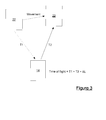
- the calculation of the round-trip time from the vessel 12 to the sensor node 14 and back to the vessel 12 can be considered in one dimension with little loss of precision, for example as can be seen from Figure 6 .
- the recorded time (in the time frame of the vessel 12) between transmission and reception is T R .
- the one-dimensional vector (distance) between the vessel 12 and the sensor node 14 is d TB
- the one-dimensional vector (distance) between the sensor node 14 and the vessel 12 (at the time of reception) is d BR .
- the vessel 12 travels along the one-dimensional vector (distance) d TR .
- the speed of sound in water is assumed to be c and the known turnaround time of the beacon is T turnaround .
- T R d TB c + d BR c + T turnaround
- the vector d TR needs to be considered.
- the speed of the transmitted signal along the vessel-to-sensor node vector is S TB
- the speed along the sensor node-to-vessel vector is S BR .
- an expression for the distance travelled by the vessel 12 can be derived.
- the speeds are calculated using a time dilation/compression technique known in the art, for example the so-called ambiguity function method or the block Doppler estimation method as described in " A computationally efficient Doppler compensation system for underwater acoustic communications" (Sharif et al., IEEE Journal of Oceanic Engineering, Jan 2000, Vol. 25 No. 1, pages 52 to 61 ), and then the summed speeds are averaged.
- the time dilation may be negative, namely an equivalence exists between time compression and time dilation.
- the speed of sound in water is assumed to be c, and so by adding equations (9) and (12), we can obtain an estimate for d TB /c, which is equivalent to T 1m used in the navigation system method previously described.
- the error in the clock, T e of the sensor node 14, with respect to the frame of the vessel 12 is ts 0 - (to + d TB /c), where t 0 is the time at which the vessel transmits the acoustic probe signal 42.
- the error calculated can be subtracted from any time communicated to the vessel 12 from the sensor node 14 in order to correct the time of arrival received to time in the context of the vessel time frame.
- the corrected time data can subsequently be used for the purpose of processing seismic data.
- seismic information can be measured using the plurality of the sensor nodes, and the time offset for each sensor node can be determined using the above technique in order to facilitate processing of the measured seismic information.
- correction for time drift can be achieved by re-sampling a recorded complete data set according to an appropriate drift model to which the data recorded is fitted, for example a non-linear drift model.
- a suitable re-sampling process can be implemented to obtain data samples at the required sampling interval, for example a so-called "piecewise polynomial process" for temporal re-sampling of data, or any other suitable technique.
- the resulting re-sampled data is in respect of the required sampling interval, for example 2ms, 4ms or 6ms, as required by seismic data analysts for performance of seismic processing, i.e. data sampled at points in time that do not conform to the desired sampling intervals, for example 1.9999ms or 2.00001ms, result in erroneous seismic processing of the data set.
- respective correction signals can be sent from the acoustic transceiver 22 of the vessel 12 to the acoustic transceiver 36 in each sensor node 14, the correction signal containing the offset time data.
- the offset time data can be used by the sensor nodes 14 in order to update the internal time of each sensor node 14.
- Step 68 an acoustic deactivation signal is sent (Step 68) from the vessel 12 to the sensor node 14 in order to power down the sensor nodes 14 or place them in a standby state.
- Time offset measurement can also be repeated a number of times during the survey as necessary/when opportune in order to improve the statistical confidence in the seismic measurements.
Landscapes
- Life Sciences & Earth Sciences (AREA)
- Physics & Mathematics (AREA)
- Remote Sensing (AREA)
- Engineering & Computer Science (AREA)
- Geology (AREA)
- Environmental & Geological Engineering (AREA)
- Acoustics & Sound (AREA)
- General Life Sciences & Earth Sciences (AREA)
- General Physics & Mathematics (AREA)
- Geophysics (AREA)
- Oceanography (AREA)
- Geophysics And Detection Of Objects (AREA)
- Measurement Of Unknown Time Intervals (AREA)
- Investigating Or Analyzing Materials By The Use Of Ultrasonic Waves (AREA)
Applications Claiming Priority (1)
| Application Number | Priority Date | Filing Date | Title |
|---|---|---|---|
| GB1108222.9A GB2491103B (en) | 2011-05-17 | 2011-05-17 | System for measuring a time offset and method of measuring a time offset |
Publications (3)
| Publication Number | Publication Date |
|---|---|
| EP2525240A2 true EP2525240A2 (fr) | 2012-11-21 |
| EP2525240A3 EP2525240A3 (fr) | 2017-04-19 |
| EP2525240B1 EP2525240B1 (fr) | 2021-07-07 |
Family
ID=44260637
Family Applications (1)
| Application Number | Title | Priority Date | Filing Date |
|---|---|---|---|
| EP12275069.8A Active EP2525240B1 (fr) | 2011-05-17 | 2012-05-17 | Système pour mesurer un décalage temporel et procédé de mesure d'un décalage temporel |
Country Status (5)
| Country | Link |
|---|---|
| US (1) | US9063249B2 (fr) |
| EP (1) | EP2525240B1 (fr) |
| BR (1) | BR102012011782B1 (fr) |
| GB (1) | GB2491103B (fr) |
| SG (1) | SG185901A1 (fr) |
Cited By (7)
| Publication number | Priority date | Publication date | Assignee | Title |
|---|---|---|---|---|
| WO2015136291A1 (fr) * | 2014-03-12 | 2015-09-17 | Sonardyne International Limited | Système de synchronisation de temps aquatique et procédé de détermination d'un décalage de temps |
| WO2015038018A3 (fr) * | 2014-11-19 | 2015-09-17 | Instytut Technik Innowacy Jnych Emag | Procédé et système de synchronisation de réseaux de mesure sismo-acoustique et sismique, en particulier de réseaux de mines à sécurité intrinsèque |
| WO2017108374A1 (fr) * | 2015-12-22 | 2017-06-29 | Philips Lighting Holding B.V. | Système de capteur |
| EP3090498A4 (fr) * | 2014-01-02 | 2017-08-16 | TrackServer, Inc. | Procédé et appareil permettant de synchroniser des horloges sous l'eau à l'aide de lumière et de son |
| WO2019168411A1 (fr) * | 2018-03-02 | 2019-09-06 | Inapril As | Procédé de correction de dérive d'horloge dans des nœuds sismiques, nœud sismique et système de gestion de nœud sismique |
| WO2020002798A1 (fr) * | 2018-06-29 | 2020-01-02 | Sercel | Procede et systeme d'estimation de la derive d'une horloge de datation d'echantillons de donnees sismiques |
| RU2729952C2 (ru) * | 2015-03-26 | 2020-08-13 | Бп Эксплорейшн Оперейтинг Компани Лимитед | Способ сейсмической съемки |
Families Citing this family (16)
| Publication number | Priority date | Publication date | Assignee | Title |
|---|---|---|---|---|
| EP2549677A1 (fr) * | 2011-07-21 | 2013-01-23 | Siemens Aktiengesellschaft | Procédé pour réaliser un système de communication et système de communication |
| US20130038358A1 (en) * | 2011-08-10 | 2013-02-14 | David M. Cook | Wireless sensor node and method |
| US9458711B2 (en) | 2012-11-30 | 2016-10-04 | XACT Downhole Telemerty, Inc. | Downhole low rate linear repeater relay network timing system and method |
| EP2959309B1 (fr) * | 2013-02-19 | 2019-05-15 | Intel IP Corporation | Techniques améliorées de localisation de réseau sans fil |
| CA2905320C (fr) | 2013-03-11 | 2022-01-04 | Ion Geophysical Corporation | Mode economie d'energie pour systemes d'acquisition de donnees sismiques de fond oceanique |
| CA2906215C (fr) | 2013-03-15 | 2021-01-19 | Xact Downhole Telemetry Inc. | Systeme et procede de reseau robuste de repeteurs de telemetrie |
| US10401523B2 (en) | 2014-07-16 | 2019-09-03 | Schlumberger Technology Corporation | Systems and methods for estimating time of flight for an acoustic wave |
| US10197680B2 (en) | 2014-08-15 | 2019-02-05 | Samsung Electronics Co., Ltd | GNSS receiver |
| US10371847B2 (en) * | 2014-09-29 | 2019-08-06 | Schlumberger Technology Corporation | System and methodology for identifying time differences between clocks during seismic exploration |
| WO2016135614A1 (fr) | 2015-02-24 | 2016-09-01 | Seabed Geosolutions Bv | Navigation radiophare de vaisseau unique et positionnement d'un nœud sismique sur le fond de l'océan |
| CN105388457B (zh) * | 2015-12-03 | 2017-10-27 | 山东科技大学 | 一种基于等效声速梯度的长基线水声定位方法 |
| EP4276008A3 (fr) | 2018-05-23 | 2024-05-29 | Blue Ocean Seismic Services Limited | Système d'acquisition de données autonomes |
| CN115427768B (zh) * | 2020-03-17 | 2025-11-28 | 伊顿智能动力有限公司 | 传感器数据集成和事件检测 |
| CN113923837B (zh) * | 2021-10-14 | 2023-07-25 | 深圳市轩火部落科技有限公司 | 圣诞灯群组显示控制方法及相关产品 |
| JP7634462B2 (ja) | 2021-11-10 | 2025-02-21 | 株式会社日立製作所 | 水中音響通信装置及び水中音響通信方法 |
| GB2613652B (en) * | 2021-12-13 | 2024-06-19 | Sonardyne Int Ltd | Subsea measurement apparatus, method of compressing measurement data and method of providing inter-compatibility between apparatus |
Family Cites Families (7)
| Publication number | Priority date | Publication date | Assignee | Title |
|---|---|---|---|---|
| FR2799004B1 (fr) * | 1999-09-27 | 2001-10-19 | Inst Francais Du Petrole | Methode et systeme de transmission utilisant un reseau de transmission standard, pour relier entre eux des elements d'un dispositif sismique |
| GB0601909D0 (en) * | 2006-01-31 | 2006-03-08 | Wireless Fibre Systems Ltd | Underwater device synchronisation system |
| KR100706568B1 (ko) * | 2006-07-18 | 2007-04-13 | 삼성전자주식회사 | 시간 오프셋 정보를 이용한 노드 위치 측정 방법 및 장치 |
| US7729204B2 (en) * | 2007-06-08 | 2010-06-01 | Microsoft Corporation | Acoustic ranging |
| US8605543B2 (en) * | 2007-09-21 | 2013-12-10 | Fairfield Industries Incorporated | Method and apparatus for correcting the timing function in a nodal seismic data acquisition unit |
| WO2011068922A2 (fr) * | 2009-12-03 | 2011-06-09 | Shell Oil Company | Correction de synchronisation d'horloge sismique utilisant les ondes acoustiques de l'océan |
| US8228757B2 (en) * | 2009-12-31 | 2012-07-24 | Wireless Seismic, Inc. | Synchronization of modules in a wireless array |
-
2011
- 2011-05-17 GB GB1108222.9A patent/GB2491103B/en active Active
-
2012
- 2012-05-16 SG SG2012035937A patent/SG185901A1/en unknown
- 2012-05-17 EP EP12275069.8A patent/EP2525240B1/fr active Active
- 2012-05-17 BR BR102012011782-7A patent/BR102012011782B1/pt active IP Right Grant
- 2012-05-17 US US13/473,944 patent/US9063249B2/en active Active
Non-Patent Citations (1)
| Title |
|---|
| SHARIF ET AL., IEEE JOURNAL OF OCEANIC ENGINEERING, vol. 25, no. 1, January 2000 (2000-01-01), pages 52 - 61 |
Cited By (15)
| Publication number | Priority date | Publication date | Assignee | Title |
|---|---|---|---|---|
| EP3090498A4 (fr) * | 2014-01-02 | 2017-08-16 | TrackServer, Inc. | Procédé et appareil permettant de synchroniser des horloges sous l'eau à l'aide de lumière et de son |
| CN106416101B (zh) * | 2014-03-12 | 2019-08-02 | 索纳达因国际有限公司 | 水中时间同步系统及确定时间偏移的方法 |
| WO2015136291A1 (fr) * | 2014-03-12 | 2015-09-17 | Sonardyne International Limited | Système de synchronisation de temps aquatique et procédé de détermination d'un décalage de temps |
| CN106416101A (zh) * | 2014-03-12 | 2017-02-15 | 索纳达因国际有限公司 | 水中时间同步系统及确定时间偏移的方法 |
| CN105829917B (zh) * | 2014-11-19 | 2019-05-07 | 伊迈格创新技术学院 | 用于地震和震声测量网络(尤其是本质安全的矿场网络)的同步的方法及系统 |
| CN105829917A (zh) * | 2014-11-19 | 2016-08-03 | 伊迈格创新技术学院 | 用于地震和震声测量网络(尤其是本质安全的矿场网络)的同步的方法及系统 |
| WO2015038018A3 (fr) * | 2014-11-19 | 2015-09-17 | Instytut Technik Innowacy Jnych Emag | Procédé et système de synchronisation de réseaux de mesure sismo-acoustique et sismique, en particulier de réseaux de mines à sécurité intrinsèque |
| RU2729952C2 (ru) * | 2015-03-26 | 2020-08-13 | Бп Эксплорейшн Оперейтинг Компани Лимитед | Способ сейсмической съемки |
| WO2017108374A1 (fr) * | 2015-12-22 | 2017-06-29 | Philips Lighting Holding B.V. | Système de capteur |
| WO2019168411A1 (fr) * | 2018-03-02 | 2019-09-06 | Inapril As | Procédé de correction de dérive d'horloge dans des nœuds sismiques, nœud sismique et système de gestion de nœud sismique |
| GB2585775A (en) * | 2018-03-02 | 2021-01-20 | Inapril As | Method for correction of clock drift in seismic nodes, a seismic node and a seismic node handling system |
| GB2585775B (en) * | 2018-03-02 | 2022-09-28 | Inapril As | Method for correction of clock drift in seismic nodes, a seismic node and a seismic node handling system |
| US11719839B2 (en) | 2018-03-02 | 2023-08-08 | Inapril As | Method for correction of clock drift in seismic nodes, a seismic node and a seismic node handling system |
| WO2020002798A1 (fr) * | 2018-06-29 | 2020-01-02 | Sercel | Procede et systeme d'estimation de la derive d'une horloge de datation d'echantillons de donnees sismiques |
| FR3083326A1 (fr) * | 2018-06-29 | 2020-01-03 | Sercel | Procede et systeme d'estimation de la derive d'une horloge de datation d'echantillons de donnees sismiques |
Also Published As
| Publication number | Publication date |
|---|---|
| US9063249B2 (en) | 2015-06-23 |
| SG185901A1 (en) | 2012-12-28 |
| US20120294112A1 (en) | 2012-11-22 |
| BR102012011782A2 (pt) | 2017-03-21 |
| EP2525240B1 (fr) | 2021-07-07 |
| EP2525240A3 (fr) | 2017-04-19 |
| GB2491103A (en) | 2012-11-28 |
| GB2491103B (en) | 2017-05-17 |
| GB201108222D0 (en) | 2011-06-29 |
| BR102012011782B1 (pt) | 2022-02-08 |
Similar Documents
| Publication | Publication Date | Title |
|---|---|---|
| EP2525240B1 (fr) | Système pour mesurer un décalage temporel et procédé de mesure d'un décalage temporel | |
| Eustice et al. | Synchronous‐clock, one‐way‐travel‐time acoustic navigation for underwater vehicles | |
| Fallon et al. | Cooperative AUV navigation using a single maneuvering surface craft | |
| Webster et al. | Advances in single-beacon one-way-travel-time acoustic navigation for underwater vehicles | |
| Gisinger et al. | In-depth verification of Sentinel-1 and TerraSAR-X geolocation accuracy using the Australian corner reflector array | |
| EP2661933B1 (fr) | Système et méthode pour synchroniser temporellement un point d'acces réseau sans fils. | |
| US9588246B2 (en) | Data collection system, marine seismic survey system and method of estimating a corrected sound speed | |
| Iinuma et al. | GNSS-Acoustic observations of seafloor crustal deformation using a wave glider | |
| WO2008141320A1 (fr) | Système de position et d'orientation post-mission haute précision | |
| CN103529461A (zh) | 一种基于强跟踪滤波和埃尔米特插值法的接收机快速定位方法 | |
| CN102209910A (zh) | 通过移动接收机优化来自卫星的扩频信号的捕捉的方法 | |
| CN108762049B (zh) | 一种基于声场互易定理的水下授时方法及系统 | |
| Busse et al. | Assessment of underwater positioning accuracy of acoustic modems using real-time kinematic GNSS | |
| AU2005268886B2 (en) | Method for an antenna angular calibration by relative distance measuring | |
| KR102288269B1 (ko) | 수중 이동체의 위치를 측정하는 방법, 장치 및 프로그램과 수중 이동체의 위치를 측정하는 시스템 | |
| Busse et al. | Towards accurate positioning of underwater vehicles using low-cost acoustic modems | |
| Sotirin et al. | Acoustic navigation of a large‐aperture array | |
| de Assis et al. | Integrating a Sonardyne Ranger 2 USBL System in the Autonomous Underwater Vehicle Eagle Ray: Operation and Post-Processing | |
| Crosbie et al. | Synchronous navigation of AUVs using WHOI micro-modem 13-bit communications | |
| Huang et al. | Precise Time Delay Measurement and Compensation for Tightly Coupled Underwater SINS/piUSBL Navigation | |
| JP2010060421A (ja) | 移動体用測位システム及びgnss受信装置 | |
| Zampieri et al. | A regularized least squares estimator for pseudorange-based terrestrial positioning under degraded geometries | |
| CN111077759B (zh) | 星载原子钟性能评估方法 | |
| KR20130111603A (ko) | 무선 네트워크 액세스 포인트들을 시간 동기화하는 시스템 및 방법 | |
| Hartnett et al. | Integrated GPS/Loran receiver for ASF propagation studies |
Legal Events
| Date | Code | Title | Description |
|---|---|---|---|
| PUAI | Public reference made under article 153(3) epc to a published international application that has entered the european phase |
Free format text: ORIGINAL CODE: 0009012 |
|
| AK | Designated contracting states |
Kind code of ref document: A2 Designated state(s): AL AT BE BG CH CY CZ DE DK EE ES FI FR GB GR HR HU IE IS IT LI LT LU LV MC MK MT NL NO PL PT RO RS SE SI SK SM TR |
|
| AX | Request for extension of the european patent |
Extension state: BA ME |
|
| RBV | Designated contracting states (corrected) |
Designated state(s): AL AT BE BG CH CY CZ DE DK EE ES FI FR GR HR HU IE IS IT LI LT LU LV MC MK MT NL NO PL PT RO RS SE SI SK SM TR |
|
| PUAL | Search report despatched |
Free format text: ORIGINAL CODE: 0009013 |
|
| AK | Designated contracting states |
Kind code of ref document: A3 Designated state(s): AL AT BE BG CH CY CZ DE DK EE ES FI FR GR HR HU IE IS IT LI LT LU LV MC MK MT NL NO PL PT RO RS SE SI SK SM TR |
|
| AX | Request for extension of the european patent |
Extension state: BA ME |
|
| RIC1 | Information provided on ipc code assigned before grant |
Ipc: G01V 1/00 20060101ALI20170315BHEP Ipc: G01V 1/38 20060101AFI20170315BHEP |
|
| STAA | Information on the status of an ep patent application or granted ep patent |
Free format text: STATUS: REQUEST FOR EXAMINATION WAS MADE |
|
| 17P | Request for examination filed |
Effective date: 20171017 |
|
| RBV | Designated contracting states (corrected) |
Designated state(s): AL AT BE BG CH CY CZ DE DK EE ES FI FR GR HR HU IE IS IT LI LT LU LV MC MK MT NL NO PL PT RO RS SE SI SK SM TR |
|
| STAA | Information on the status of an ep patent application or granted ep patent |
Free format text: STATUS: EXAMINATION IS IN PROGRESS |
|
| 17Q | First examination report despatched |
Effective date: 20191209 |
|
| GRAP | Despatch of communication of intention to grant a patent |
Free format text: ORIGINAL CODE: EPIDOSNIGR1 |
|
| STAA | Information on the status of an ep patent application or granted ep patent |
Free format text: STATUS: GRANT OF PATENT IS INTENDED |
|
| INTG | Intention to grant announced |
Effective date: 20201202 |
|
| GRAS | Grant fee paid |
Free format text: ORIGINAL CODE: EPIDOSNIGR3 |
|
| GRAA | (expected) grant |
Free format text: ORIGINAL CODE: 0009210 |
|
| STAA | Information on the status of an ep patent application or granted ep patent |
Free format text: STATUS: THE PATENT HAS BEEN GRANTED |
|
| AK | Designated contracting states |
Kind code of ref document: B1 Designated state(s): AL AT BE BG CH CY CZ DE DK EE ES FI FR GR HR HU IE IS IT LI LT LU LV MC MK MT NL NO PL PT RO RS SE SI SK SM TR |
|
| REG | Reference to a national code |
Ref country code: AT Ref legal event code: REF Ref document number: 1409129 Country of ref document: AT Kind code of ref document: T Effective date: 20210715 |
|
| REG | Reference to a national code |
Ref country code: DE Ref legal event code: R096 Ref document number: 602012076028 Country of ref document: DE |
|
| REG | Reference to a national code |
Ref country code: IE Ref legal event code: FG4D |
|
| REG | Reference to a national code |
Ref country code: NO Ref legal event code: T2 Effective date: 20210707 |
|
| REG | Reference to a national code |
Ref country code: LT Ref legal event code: MG9D |
|
| REG | Reference to a national code |
Ref country code: NL Ref legal event code: MP Effective date: 20210707 |
|
| REG | Reference to a national code |
Ref country code: AT Ref legal event code: MK05 Ref document number: 1409129 Country of ref document: AT Kind code of ref document: T Effective date: 20210707 |
|
| PG25 | Lapsed in a contracting state [announced via postgrant information from national office to epo] |
Ref country code: SE Free format text: LAPSE BECAUSE OF FAILURE TO SUBMIT A TRANSLATION OF THE DESCRIPTION OR TO PAY THE FEE WITHIN THE PRESCRIBED TIME-LIMIT Effective date: 20210707 Ref country code: HR Free format text: LAPSE BECAUSE OF FAILURE TO SUBMIT A TRANSLATION OF THE DESCRIPTION OR TO PAY THE FEE WITHIN THE PRESCRIBED TIME-LIMIT Effective date: 20210707 Ref country code: AT Free format text: LAPSE BECAUSE OF FAILURE TO SUBMIT A TRANSLATION OF THE DESCRIPTION OR TO PAY THE FEE WITHIN THE PRESCRIBED TIME-LIMIT Effective date: 20210707 Ref country code: BG Free format text: LAPSE BECAUSE OF FAILURE TO SUBMIT A TRANSLATION OF THE DESCRIPTION OR TO PAY THE FEE WITHIN THE PRESCRIBED TIME-LIMIT Effective date: 20211007 Ref country code: LT Free format text: LAPSE BECAUSE OF FAILURE TO SUBMIT A TRANSLATION OF THE DESCRIPTION OR TO PAY THE FEE WITHIN THE PRESCRIBED TIME-LIMIT Effective date: 20210707 Ref country code: RS Free format text: LAPSE BECAUSE OF FAILURE TO SUBMIT A TRANSLATION OF THE DESCRIPTION OR TO PAY THE FEE WITHIN THE PRESCRIBED TIME-LIMIT Effective date: 20210707 Ref country code: NL Free format text: LAPSE BECAUSE OF FAILURE TO SUBMIT A TRANSLATION OF THE DESCRIPTION OR TO PAY THE FEE WITHIN THE PRESCRIBED TIME-LIMIT Effective date: 20210707 Ref country code: PT Free format text: LAPSE BECAUSE OF FAILURE TO SUBMIT A TRANSLATION OF THE DESCRIPTION OR TO PAY THE FEE WITHIN THE PRESCRIBED TIME-LIMIT Effective date: 20211108 Ref country code: FI Free format text: LAPSE BECAUSE OF FAILURE TO SUBMIT A TRANSLATION OF THE DESCRIPTION OR TO PAY THE FEE WITHIN THE PRESCRIBED TIME-LIMIT Effective date: 20210707 Ref country code: ES Free format text: LAPSE BECAUSE OF FAILURE TO SUBMIT A TRANSLATION OF THE DESCRIPTION OR TO PAY THE FEE WITHIN THE PRESCRIBED TIME-LIMIT Effective date: 20210707 |
|
| PG25 | Lapsed in a contracting state [announced via postgrant information from national office to epo] |
Ref country code: PL Free format text: LAPSE BECAUSE OF FAILURE TO SUBMIT A TRANSLATION OF THE DESCRIPTION OR TO PAY THE FEE WITHIN THE PRESCRIBED TIME-LIMIT Effective date: 20210707 Ref country code: LV Free format text: LAPSE BECAUSE OF FAILURE TO SUBMIT A TRANSLATION OF THE DESCRIPTION OR TO PAY THE FEE WITHIN THE PRESCRIBED TIME-LIMIT Effective date: 20210707 Ref country code: GR Free format text: LAPSE BECAUSE OF FAILURE TO SUBMIT A TRANSLATION OF THE DESCRIPTION OR TO PAY THE FEE WITHIN THE PRESCRIBED TIME-LIMIT Effective date: 20211008 |
|
| REG | Reference to a national code |
Ref country code: DE Ref legal event code: R097 Ref document number: 602012076028 Country of ref document: DE |
|
| PG25 | Lapsed in a contracting state [announced via postgrant information from national office to epo] |
Ref country code: DK Free format text: LAPSE BECAUSE OF FAILURE TO SUBMIT A TRANSLATION OF THE DESCRIPTION OR TO PAY THE FEE WITHIN THE PRESCRIBED TIME-LIMIT Effective date: 20210707 |
|
| PLBE | No opposition filed within time limit |
Free format text: ORIGINAL CODE: 0009261 |
|
| STAA | Information on the status of an ep patent application or granted ep patent |
Free format text: STATUS: NO OPPOSITION FILED WITHIN TIME LIMIT |
|
| PG25 | Lapsed in a contracting state [announced via postgrant information from national office to epo] |
Ref country code: SM Free format text: LAPSE BECAUSE OF FAILURE TO SUBMIT A TRANSLATION OF THE DESCRIPTION OR TO PAY THE FEE WITHIN THE PRESCRIBED TIME-LIMIT Effective date: 20210707 Ref country code: SK Free format text: LAPSE BECAUSE OF FAILURE TO SUBMIT A TRANSLATION OF THE DESCRIPTION OR TO PAY THE FEE WITHIN THE PRESCRIBED TIME-LIMIT Effective date: 20210707 Ref country code: RO Free format text: LAPSE BECAUSE OF FAILURE TO SUBMIT A TRANSLATION OF THE DESCRIPTION OR TO PAY THE FEE WITHIN THE PRESCRIBED TIME-LIMIT Effective date: 20210707 Ref country code: EE Free format text: LAPSE BECAUSE OF FAILURE TO SUBMIT A TRANSLATION OF THE DESCRIPTION OR TO PAY THE FEE WITHIN THE PRESCRIBED TIME-LIMIT Effective date: 20210707 Ref country code: CZ Free format text: LAPSE BECAUSE OF FAILURE TO SUBMIT A TRANSLATION OF THE DESCRIPTION OR TO PAY THE FEE WITHIN THE PRESCRIBED TIME-LIMIT Effective date: 20210707 Ref country code: AL Free format text: LAPSE BECAUSE OF FAILURE TO SUBMIT A TRANSLATION OF THE DESCRIPTION OR TO PAY THE FEE WITHIN THE PRESCRIBED TIME-LIMIT Effective date: 20210707 |
|
| 26N | No opposition filed |
Effective date: 20220408 |
|
| PG25 | Lapsed in a contracting state [announced via postgrant information from national office to epo] |
Ref country code: IT Free format text: LAPSE BECAUSE OF FAILURE TO SUBMIT A TRANSLATION OF THE DESCRIPTION OR TO PAY THE FEE WITHIN THE PRESCRIBED TIME-LIMIT Effective date: 20210707 |
|
| REG | Reference to a national code |
Ref country code: DE Ref legal event code: R119 Ref document number: 602012076028 Country of ref document: DE |
|
| REG | Reference to a national code |
Ref country code: CH Ref legal event code: PL |
|
| REG | Reference to a national code |
Ref country code: BE Ref legal event code: MM Effective date: 20220531 |
|
| PG25 | Lapsed in a contracting state [announced via postgrant information from national office to epo] |
Ref country code: MC Free format text: LAPSE BECAUSE OF FAILURE TO SUBMIT A TRANSLATION OF THE DESCRIPTION OR TO PAY THE FEE WITHIN THE PRESCRIBED TIME-LIMIT Effective date: 20210707 Ref country code: LU Free format text: LAPSE BECAUSE OF NON-PAYMENT OF DUE FEES Effective date: 20220517 Ref country code: LI Free format text: LAPSE BECAUSE OF NON-PAYMENT OF DUE FEES Effective date: 20220531 Ref country code: CH Free format text: LAPSE BECAUSE OF NON-PAYMENT OF DUE FEES Effective date: 20220531 |
|
| PG25 | Lapsed in a contracting state [announced via postgrant information from national office to epo] |
Ref country code: IE Free format text: LAPSE BECAUSE OF NON-PAYMENT OF DUE FEES Effective date: 20220517 |
|
| PG25 | Lapsed in a contracting state [announced via postgrant information from national office to epo] |
Ref country code: DE Free format text: LAPSE BECAUSE OF NON-PAYMENT OF DUE FEES Effective date: 20221201 Ref country code: BE Free format text: LAPSE BECAUSE OF NON-PAYMENT OF DUE FEES Effective date: 20220531 |
|
| P01 | Opt-out of the competence of the unified patent court (upc) registered |
Effective date: 20230530 |
|
| PG25 | Lapsed in a contracting state [announced via postgrant information from national office to epo] |
Ref country code: HU Free format text: LAPSE BECAUSE OF FAILURE TO SUBMIT A TRANSLATION OF THE DESCRIPTION OR TO PAY THE FEE WITHIN THE PRESCRIBED TIME-LIMIT; INVALID AB INITIO Effective date: 20120517 |
|
| PG25 | Lapsed in a contracting state [announced via postgrant information from national office to epo] |
Ref country code: MK Free format text: LAPSE BECAUSE OF FAILURE TO SUBMIT A TRANSLATION OF THE DESCRIPTION OR TO PAY THE FEE WITHIN THE PRESCRIBED TIME-LIMIT Effective date: 20210707 Ref country code: CY Free format text: LAPSE BECAUSE OF FAILURE TO SUBMIT A TRANSLATION OF THE DESCRIPTION OR TO PAY THE FEE WITHIN THE PRESCRIBED TIME-LIMIT Effective date: 20210707 |
|
| PG25 | Lapsed in a contracting state [announced via postgrant information from national office to epo] |
Ref country code: TR Free format text: LAPSE BECAUSE OF FAILURE TO SUBMIT A TRANSLATION OF THE DESCRIPTION OR TO PAY THE FEE WITHIN THE PRESCRIBED TIME-LIMIT Effective date: 20210707 |
|
| PG25 | Lapsed in a contracting state [announced via postgrant information from national office to epo] |
Ref country code: MT Free format text: LAPSE BECAUSE OF FAILURE TO SUBMIT A TRANSLATION OF THE DESCRIPTION OR TO PAY THE FEE WITHIN THE PRESCRIBED TIME-LIMIT Effective date: 20210707 |
|
| PGFP | Annual fee paid to national office [announced via postgrant information from national office to epo] |
Ref country code: NO Payment date: 20250526 Year of fee payment: 14 |
|
| PGFP | Annual fee paid to national office [announced via postgrant information from national office to epo] |
Ref country code: FR Payment date: 20250522 Year of fee payment: 14 |