EP2525355B1 - Appareil de codage audio et procédé de codage audio - Google Patents
Appareil de codage audio et procédé de codage audio Download PDFInfo
- Publication number
- EP2525355B1 EP2525355B1 EP11732797.3A EP11732797A EP2525355B1 EP 2525355 B1 EP2525355 B1 EP 2525355B1 EP 11732797 A EP11732797 A EP 11732797A EP 2525355 B1 EP2525355 B1 EP 2525355B1
- Authority
- EP
- European Patent Office
- Prior art keywords
- coding
- signal
- section
- coefficients
- weighting
- Prior art date
- Legal status (The legal status is an assumption and is not a legal conclusion. Google has not performed a legal analysis and makes no representation as to the accuracy of the status listed.)
- Not-in-force
Links
Images


Classifications
-
- G—PHYSICS
- G10—MUSICAL INSTRUMENTS; ACOUSTICS
- G10L—SPEECH ANALYSIS TECHNIQUES OR SPEECH SYNTHESIS; SPEECH RECOGNITION; SPEECH OR VOICE PROCESSING TECHNIQUES; SPEECH OR AUDIO CODING OR DECODING
- G10L19/00—Speech or audio signals analysis-synthesis techniques for redundancy reduction, e.g. in vocoders; Coding or decoding of speech or audio signals, using source filter models or psychoacoustic analysis
- G10L19/02—Speech or audio signals analysis-synthesis techniques for redundancy reduction, e.g. in vocoders; Coding or decoding of speech or audio signals, using source filter models or psychoacoustic analysis using spectral analysis, e.g. transform vocoders or subband vocoders
- G10L19/0212—Speech or audio signals analysis-synthesis techniques for redundancy reduction, e.g. in vocoders; Coding or decoding of speech or audio signals, using source filter models or psychoacoustic analysis using spectral analysis, e.g. transform vocoders or subband vocoders using orthogonal transformation
-
- G—PHYSICS
- G10—MUSICAL INSTRUMENTS; ACOUSTICS
- G10L—SPEECH ANALYSIS TECHNIQUES OR SPEECH SYNTHESIS; SPEECH RECOGNITION; SPEECH OR VOICE PROCESSING TECHNIQUES; SPEECH OR AUDIO CODING OR DECODING
- G10L19/00—Speech or audio signals analysis-synthesis techniques for redundancy reduction, e.g. in vocoders; Coding or decoding of speech or audio signals, using source filter models or psychoacoustic analysis
- G10L19/04—Speech or audio signals analysis-synthesis techniques for redundancy reduction, e.g. in vocoders; Coding or decoding of speech or audio signals, using source filter models or psychoacoustic analysis using predictive techniques
- G10L19/16—Vocoder architecture
- G10L19/18—Vocoders using multiple modes
- G10L19/24—Variable rate codecs, e.g. for generating different qualities using a scalable representation such as hierarchical encoding or layered encoding
-
- G—PHYSICS
- G10—MUSICAL INSTRUMENTS; ACOUSTICS
- G10L—SPEECH ANALYSIS TECHNIQUES OR SPEECH SYNTHESIS; SPEECH RECOGNITION; SPEECH OR VOICE PROCESSING TECHNIQUES; SPEECH OR AUDIO CODING OR DECODING
- G10L19/00—Speech or audio signals analysis-synthesis techniques for redundancy reduction, e.g. in vocoders; Coding or decoding of speech or audio signals, using source filter models or psychoacoustic analysis
- G10L19/04—Speech or audio signals analysis-synthesis techniques for redundancy reduction, e.g. in vocoders; Coding or decoding of speech or audio signals, using source filter models or psychoacoustic analysis using predictive techniques
- G10L19/08—Determination or coding of the excitation function; Determination or coding of the long-term prediction parameters
- G10L19/12—Determination or coding of the excitation function; Determination or coding of the long-term prediction parameters the excitation function being a code excitation, e.g. in code excited linear prediction [CELP] vocoders
Definitions
- the present invention relates to an encoding speech apparatus and an encoding speech method.
- Speech coding techniques are categorized into mainly two coding techniques, i.e., transform coding and linear predictive coding.
- the transform coding transforms signals from a time domain into a spectral domain and then encodes spectral coefficients using a discrete Fourier transform (DFT) or a modified discrete cosine transform (MDCT), for example.
- DFT discrete Fourier transform
- MDCT modified discrete cosine transform
- the coding process generally involves calculating perceptual importance levels of the spectral coefficients using a psychoacoustic model and then encoding the spectral coefficients according to each perceptual importance level.
- Some common transform coding techniques include MPEG MP3, MPEG AAC, and Dolby AC3.
- the transform coding is effective for music signals and general speech signals.
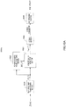
- FIG.1 illustrates a configuration of the transform coding.
- time-frequency transforming section 101 transforms time domain signal S(n) into frequency domain signal S(f) using time-frequency transformation such as discrete Fourier transform (DFT) or modified discrete cosine transform (MDCT).
- DFT discrete Fourier transform
- MDCT modified discrete cosine transform
- Psychoacoustic model analyzing section 103 performs a psychoacoustic model analysis on frequency domain signal S(f) to calculate a masking curve.
- coding section 102 encodes frequency domain signal S(f) not to create quantization noise.
- Multiplexing section 104 multiplexes the coding parameter generated at coding section 102 with the signal to generate bit stream information, and transmits the bit stream information to a decoding side.
- demultiplexing section 105 demultiplexes the bit stream information to generate the coding parameter.
- Decoding section 106 decodes the coding parameter to generate decoded frequency domain signal S ⁇ (f).
- frequency-time transforming section 107 transforms decoded frequency domain signal S ⁇ (f) into a time domain, to generate decoded time domain signal S ⁇ (n).
- IDDCT inverse discrete Fourier transform
- IMDCT inverse modified discrete cosine transform
- the linear predictive coding obtains a residual/excitation signal by using redundancy of a speech signal in a time domain and applying linear prediction to an input speech signal.
- the linear predictive coding efficiently generates an audio playback signal.
- main two different techniques such as TCX and CELP encode the residual/excitation signal.
- TCX efficiently transforms and encodes the residual/excitation signal in a frequency domain.
- Some common TCX coding techniques include 3GPP AMR-WB+, MPEG USAC, for example.
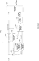
- FIG.2 illustrates a configuration of the TCX coding.
- LPC analyzing section 201 performs LPC analysis on an input signal to use redundancy of a signal in a time domain.
- Coding section 202 encodes the LPC coefficients from LPC analyzing section 201.
- Decoding section 203 decodes the encoded LPC coefficients.
- Inverse filter section 204 applies an LPC inverse filter to input signal S(n), using the decoded LPC coefficients from decoding section 203, to obtain residual (excitation) signal S r (n).
- Time-frequency transforming section 205 transforms residual signal S r (n) into frequency domain signal S r (f) using time-frequency transformation such as discrete Fourier transform (DFT) or modified discrete cosine transform (MDCT).
- DFT discrete Fourier transform
- MDCT modified discrete cosine transform
- Coding section 206 encodes S r (f).
- Multiplexing section 207 multiplexes the LPC coefficients generated and encoded at coding section 202 and the coding parameter generated at coding section 206 to generate bit stream information, and transmits the bit stream information to the decoding side.
- demultiplexing section 208 demultiplexes the bit stream information to generate the encoded LPC coefficients and coding parameter.
- Decoding section 210 decodes the coding parameter to generate decoded residual signal S r ⁇ (f) of a frequency domain.
- LPC coefficient decoding section 209 decodes the encoded LPC coefficients to obtain LPC coefficients.
- frequency-time transforming section 211 transforms decoded residual signal S r ⁇ (f) of a frequency domain into a time domain, to generate decoded residual signal S r ⁇ (n) of the time domain.
- IDDCT inverse discrete Fourier transform
- IMDCT inverse modified discrete cosine transform
- Synthesis filter 212 performs LPC synthesis filtering processing on decoded residual signal S r ⁇ (n) of the time domain using the LPC coefficients decoded at LPC coefficient decoding section 209, to obtain decoded time domain signal S ⁇ (n).
- CELP coding encodes a residual/excitation signal using a predetermined code book.
- the CELP coding transforms an error signal into a frequency domain for coding, the error signal between the original signal and an LPC synthesized signal.
- Common CELP coding techniques include ITU-T G.729.1, ITU-T G.718, for example.
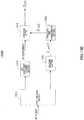
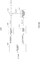
- FIG.3 illustrates a configuration of coding combining the CELP coding and the transform coding.
- CELP coding section 301 performs the CELP coding on an input signal to use redundancy of a signal in a time domain.
- CELP decoding section 302 generates synthesized signal S syn (n) using a CELP parameter generated at CELP coding section 301.
- Time-frequency transforming section 303 transforms error signal S e (n) into frequency domain signal S e (f) (spectral coefficients) using time-frequency transformation such as discrete Fourier transform (DFT) or modified discrete cosine transform (MDCT).
- DFT discrete Fourier transform
- MDCT modified discrete cosine transform
- Coding section 304 encodes S e (f).
- Multiplexing section 305 multiplexes the CELP parameter generated at CELP coding section 301 and the coding parameter generated at coding section 304 to generate bit stream information, and transmits the bit stream information to the decoding side.
- demultiplexing section 306 demultiplexes the bit stream information to generate the CELP parameter and the coding parameter.
- Decoding section 308 decodes the coding parameter to generate decoded residual signal S e ⁇ (f) of a frequency domain.
- CELP decoding section 307 generates CELP synthesized signal S syn (n) using the CELP parameter.
- Frequency-time transforming section 309 transforms decoded residual signal S e ⁇ (f) of a frequency domain into a time domain using frequency-time transformation such as inverse discrete Fourier transform (IDFT) or inverse modified discrete cosine transform (IMDCT), to generate decoded residual signal (predictive error signal) S e ⁇ (n) of the time domain.
- frequency-time transformation such as inverse discrete Fourier transform (IDFT) or inverse modified discrete cosine transform (IMDCT)
- Adder 311 generates decoded time domain signal S ⁇ (n) by adding CELP synthesized signal S syn (n) and decoded predictive error signal S e ⁇ (n).
- Transform coding and linear predictive coding apply a certain coding technique to a signal of a frequency domain, that is, spectral coefficients (transform coefficients).
- coding of spectral coefficients by transform coding calculates weighting coefficients representing the perceptual importance level of the spectral coefficients, to use for encoding the spectral coefficients.
- the transform coding generally calculates perceptually-weighting coefficients according to a psychoacoustic model to use masking phenomenon which is specific to human hearing mechanism.
- the linear predictive coding performs linear prediction on an input signal, it is not easy to obtain a psychoacoustic model.
- the perceptually-weighting coefficients are generally calculated based on an energy-to-noise ratio or a signal-to-noise ratio.
- pulse vector coding the coding of the spectral coefficients applied to the transform coding or the linear predictive coding.
- the factorial pulse coding is pulse vector coding in which coding information is a unit magnitude pulse.
- the spectral coefficients which are coding targets are represented by a plurality of pulses, and the positions, amplitudes, and polarities of these pulses are calculated, to encode this information.
- a global gain is also calculated for coding.
- the coding parameter of the pulse vector coding includes a global gain, a pulse position, a pulse amplitude, and a pulse polarity.
- FIG.6 shows a concept of the pulse vector coding.
- TDAC Time Domain Aliasing Cancellation
- FIG.7 illustrates a configuration of the TDAC coding in G.729.1.
- band splitting section 701 splits input signal S(f) (spectral coefficients) into a plurality of subbands.
- the low band section of the input signal is formed by error-signal MDCT coefficients between the original signal and a CELP decoded signal
- the high band section of the input signal is formed by MDCT coefficients of the original signal.
- Spectrum envelope calculating section 702 calculates a spectrum envelope (energy of each subband) for each subband signal ⁇ S sb (f) ⁇ .
- Coding section 703 encodes the spectrum envelope.
- Bit allocating section 704 calculates the order of perceptual importance levels ⁇ ip sb ⁇ according to the encoded spectrum envelopes, to allocate bits to subbands.
- Vector quantizing section 705 uses the allocated bits and split spherical VQ method to encode subband signal ⁇ S sb (f) ⁇ .
- Calculating the perceptual importance level on a subband basis means that the all perceptual importance levels of the spectral coefficients included in each of the subbands are the same.
- pulse vector coding selects spectral coefficients to be encoded, based on amplitude values of spectral coefficients.
- the perceptual importance level calculated on a subband basis cannot accurately represent the perceptual importance level of spectral coefficients.
- a certain subband includes five spectral coefficients S sb (f0), S sb (f1), S sb (f2), S sb (f3), and S sb (f4) as illustrated in FIG.8 .
- pulse vector coding is adopted as a coding method in this case. Assuming that S sb (f1) has the largest amplitude among the five spectral coefficients and coding bits allocated to this subband can encode only one pulse in this case, the pulse vector coding selects and encodes S sb (f1). Here, even if the perceptual importance levels are calculated in this subband, S sb (f1) is still encoded.
- the technique performs the distribution of coding bits and perceptual weighting processing on a subband basis. That is, the differences among the perceptual importance levels of spectral coefficients included in a subband are not taken into consideration.
- US 2007/016404 A1 discloses an method and apparatus to extract an audio signal having an important spectral component (ISC) and a low bit-rate audio signal coding/decoding method using the method and apparatus to extract the ISC.
- the method of extracting the ISC includes calculating perceptual importance including an SMR (signal-to-mark ratio) value of transformed spectral audio signals by using a psychoacoustic model, selecting spectral signals having a masking threshold value smaller than that of the spectral audio signals using the SMR value as first ISCs, and extracting a spectral peak from the audio signals selected as the ISCs according to a predetermined weighting factor to select second ISCs.
- SMR signal-to-mark ratio
- the speech coding apparatus of the present invention employs a configuration having the features of claim 1 including at least two layers of a lower layer and a higher layer, employs a configuration having: a generating section that generates an error signal between a decoded signal of the lower layer and an input signal; an estimation section that calculates a signal-to-noise ratio using the input signal and the error signal and estimates respective perceptual importance levels of a plurality of spectral coefficients of different frequencies in the error signal, based on the signal-to-noise ratio; a calculating section that calculates respective weighting coefficients of a plurality of spectral coefficients based on the respective estimated importance levels; a weighting section that weights each of a plurality of spectral coefficients using the respective calculated weighting coefficients; and a coding section that encodes a plurality of weighted spectral coefficients.
- the speech coding method of the present invention comprises the steps of claim 2.
- the decoding side can obtain a decoded signal with good sound quality.
- the present invention calculates the perceptual importance level, not on a subband basis but on each spectral coefficient basis in encoding spectral coefficients.
- the present invention calculates respective weighting coefficients for applying the weighting coefficients to the spectral coefficients, according to a psychoacoustic model analysis, a signal-to-noise ratio, or the resulting perceptual importance levels based on a parameter related to a perceptual system.
- the weighting coefficient is larger as the perceptual importance level of a spectral coefficient is higher, and the weighting coefficient is smaller as the perceptual importance level is lower. Thus, it is possible to obtain perceptually good sound quality by encoding a perceptually-weighted spectral coefficient.
- the present invention determines the perceptual importance level according to a masking curve as illustrated in FIG.9 .
- the perceptual importance level shows that S sb (f1) has the largest amplitude but is not perceptually important. For this reason, assignment of a low weight to S sb (f1) with low perceptual importance level suppresses S sb (f1). As a result, the most perceptually-important S sb (f3) will be encoded.
- a first example determines respective perceptual importance levels of spectral coefficients, then determines weighting coefficients according to the perceptual importance levels, applies the weighting coefficients to the spectral coefficients, respectively, and encodes the perceptually-weighted spectral coefficients.
- the perceptually-weighting coefficients are more accurate because the coefficients are calculated respectively for the spectral coefficients. It is therefore possible to select and encode the most perceptually-important spectral coefficient, and thereby to obtain better coding performance (improvement in sound quality).
- the decoding side does not perform inverse weighting processing corresponding to the application at the coding side.
- layer coding updates the perceptual importance level of an error signal in each layer.
- the layer coding calculates the weight according to the perceptual importance level and applied to each coding-target spectral coefficient.
- FIG.10A illustrates a configuration of speech coding apparatus 1000A according to an example.
- FIG.10B illustrates a configuration of speech decoding apparatus 1000B according to another example.
- a pulse vector coding perceptually weights each spectral coefficient.
- time-frequency transforming section 1001 transforms time domain signal S(n) into frequency domain signal S(f) (spectral coefficients), using time-frequency transformation such as discrete Fourier transform (DFT) or modified discrete cosine transform (MDCT).
- DFT discrete Fourier transform
- MDCT modified discrete cosine transform
- Psychoacoustic model analyzing section 1002 determines a masking curve by performing a psychoacoustic model analysis on frequency domain signal S(f).
- Perceptually-weighting section 1003 estimates perceptual importance levels based on the masking curve, and calculates respective weighting coefficients for the spectral coefficients according to the perceptual importance levels, to apply the weighting coefficients to the spectral coefficients, respectively.
- Coding section 1004 encodes perceptually-weighted frequency domain signal S PW (f) to generate a coding parameter.
- Multiplexing section 1005 multiplexes the coding parameter with the signal to generate bit stream information and transmits the bit stream information to speech decoding apparatus 1000B ( FIG.10B ).
- demultiplexing section 1006 demultiplexes the bit stream information to generate the coding parameter.
- Decoding section 1007 decodes the coding parameter to generate decoded frequency domain signal S ⁇ (f).
- Frequency-time transforming section 1008 transforms decoded frequency domain signal S ⁇ (f) into a time domain using frequency-time transformation such as inverse discrete Fourier transform (IDFT) or inverse modified discrete cosine transform (IMDCT), to generate decoded time domain signal S ⁇ (n).
- frequency-time transformation such as inverse discrete Fourier transform (IDFT) or inverse modified discrete cosine transform (IMDCT)
- FIG.11 illustrates a configuration of perceptually-weighting section 1003 according to the present example.
- FIG.11 illustrates a configuration to perceptually weight each spectral coefficient.
- estimation section 1101 estimates perceptual importance level pi(f) of each spectral coefficient, according to masking curve M(f).
- Perceptual importance level pi(f) is the parameter quantitatively representing how perceptually important the spectral coefficient is.
- Perceptual importance level pi(f) showing a larger value means that the spectral coefficient corresponding to the pi(f) is perceptually important.
- Weighting section 1103 multiplies spectral coefficient S(f) by weighting coefficient W(f) to generate perceptually-weighted spectral coefficient S PW (f).
- spectral coefficient S PW (f) is calculated as the following equation.
- S PW f W f * S f
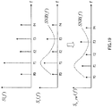
- FIG.12 illustrates a state where each spectral coefficient is perceptually weighted.
- energy levels of spectral coefficient S(f0) and S(f4) are lower than points of masking curve M(f0) and M(f1), respectively.
- weighting coefficients W(f0) and W(f4) multiplied to these two spectral coefficients respectively are less than 1, and hence the energy levels of spectral coefficients S(f0) and S(f4) are suppressed.
- perceptually-weighted spectral coefficients S PW (f0) and S PW (f4) are represented as the following, and reveal that those coefficients S PW (f0) and S PW (f4) become lower than spectral coefficients S(f0) and S(f4) respectively.
- a pulse vector coding determines the perceptual importance levels of the spectral coefficients, determines weighting coefficients according to the perceptual importance levels, applies the weighting coefficients to the respective spectral coefficients, and encodes the perceptually-weighted spectral coefficients.
- the perceptually-weighting coefficients can calculate each spectral coefficient more accurately, in comparison with performing perceptual-weighting processing on a subband basis.
- the decoding side (speech decoding apparatus 1000B) does not perform inverse weighting processing with respect to the above processing.
- FIG.13A illustrates a configuration of speech coding apparatus 1300A according to the present example.
- FIG.13B also illustrates a configuration of speech decoding apparatus 1300B according to the present example.
- a TCX coding perceptually weights each spectral coefficient.
- LPC analyzing section 1301 performs LPC analysis on an input signal, so as to use redundancy of a signal in a time domain.
- Coding section 1302 encodes the LPC coefficients from LPC analyzing section 1301.
- Decoding section 1303 decodes the encoded LPC coefficients.
- Inverse filter section 1304 obtains residual (excitation) signal S r (n) by applying an LPC inverse filter to input signal S(n) using the decoded LPC coefficients from decoding section 1303.
- Time-frequency transforming section 1305 transforms residual signal S r (n) into frequency domain signal S r (f) (spectral coefficients) using time-frequency transformation such as discrete Fourier transform (DFT) or modified discrete cosine transform (MDCT).
- DFT discrete Fourier transform
- MDCT modified discrete cosine transform
- Time-frequency transforming section 1306 transforms original signal S(n) into frequency domain signal S(f) (spectral coefficients) using time-frequency transformation such as discrete Fourier transform (DFT) or modified discrete cosine transform (MDCT).
- DFT discrete Fourier transform
- MDCT modified discrete cosine transform
- Perceptually-weighting section 1307 performing a psychoacoustic model analysis on frequency domain signal S(f), to calculate a masking curve.
- Perceptually-weighting section 1307 estimates the perceptual importance level based on the masking curve, calculates respective weighting coefficients of the spectral coefficients, and then applies the respective weighting coefficients to the spectral coefficients.
- Coding section 1308 encodes perceptually-weighted residual signal S r_PW (f) to generate a coding parameter.
- Multiplexing section 1309 multiplexes the coding parameter with the signal to generated bit stream information, and transmits the bit stream information to the decoding side.
- demultiplexing section 1310 demultiplexes the bit stream information to generate the coding parameter and LPC coefficients.
- Decoding section 1311 decodes the coding parameter to generate decoded residual signal S r ⁇ _PW (f) of a frequency domain.
- LPC coefficient decoding section 1313 decodes the LPC coefficients.
- Frequency-time transforming section 1312 transforms decoded residual signal S r ⁇ _PW (f) of a frequency domain into a time domain using frequency-time transformation such as inverse discrete Fourier transform (IDFT) or inverse modified discrete cosine transform (IMDCT), to generate decoded residual signal S r ⁇ (n) of a time domain.
- frequency-time transformation such as inverse discrete Fourier transform (IDFT) or inverse modified discrete cosine transform (IMDCT)
- Synthesis filter 1314 performs LPC synthesis filtering processing on decoded residual signal S r ⁇ (n) of a time domain using the decoded LPC coefficients from LPC coefficient decoding section 1313, to obtain decoded time domain signal S ⁇ (n).
- FIG.14 illustrates a configuration of perceptually-weighting section 1307 according to the present example.
- FIG.14 illustrates a configuration to perceptually weight each spectral coefficient.
- the same components as in FIG.11 will be assigned the same reference numerals and detail explanations thereof will be omitted.
- psychoacoustic model analyzing section 1401 calculates masking curve M(f) based on spectral coefficient S(f) of an original signal.
- FIG.15 illustrates a state to perceptually weight each spectral coefficient.
- energy levels of spectral coefficients S(f0), S(f1), S(f2), and S(f4) are lower than points of masking curve M(f0), M(f1), M(f2), and M(f4), respectively.
- the energy levels of these spectral coefficients are suppressed not to waste bits in encoding these spectral coefficients.
- TCX coding determines the perceptual importance levels of the respective spectral coefficients, determines weighting coefficients according to the perceptual importance levels, applies the respective weighting coefficients to the spectral coefficients, and encodes the perceptually-weighted spectral coefficients.
- the perceptually-weighting coefficients can calculate each spectral coefficient more accurately, in comparison with performing perceptual-weighting processing on a subband basis.
- the decoding side (speech decoding apparatus 1300A) applies perceptually-weighting coefficients. That is, the decoding side (speech decoding apparatus 1300B) does not perform inverse weighting processing with respect to the above processing.
- FIG.16A illustrates a configuration of speech coding apparatus 1600A according to the present embodiment.
- FIG.16B also illustrates a configuration of speech decoding apparatus 1600B.
- layer coding (scalable coding), in which a lower layer adopts a CELP coding and a higher layer adopts a transform coding, perceptually weights each spectral coefficient.
- layer coding including two layers of the lower layer and the higher layer will be explained as an example, it is possible to apply the present invention to the layer coding including three layers or more.
- CELP coding section 1601 performs a CELP coding on an input signal so as to use redundancy of a signal in a time domain.
- CELP decoding section 1602 generates synthesized signal S syn (n) using the CELP parameter.
- subtractor 1612 By subtracting the synthesized signal from the input signal, subtractor 1612 obtains error signal S e (n) (error signal between the input signal and the synthesized signal).
- Time-frequency transforming section 1604 transforms error signal S e (n) into frequency domain signal S e (f) (spectral coefficients) using time-frequency transformation such as discrete Fourier transform (DFT) or modified discrete cosine transform (MDCT).
- DFT discrete Fourier transform
- MDCT modified discrete cosine transform
- Time-frequency transforming section 1603 transforms synthesized signal S syn (n) from CELP decoding section 1602 into frequency domain signal S syn (f) (spectral coefficients) using time-frequency transformation such as discrete Fourier transform (DFT) or modified discrete cosine transform (MDCT).
- DFT discrete Fourier transform
- MDCT modified discrete cosine transform
- Perceptually-weighting section 1605 applies perceptual weighting of each spectral coefficient to spectral coefficient S e (f).
- perceptually-weighting coefficients are calculated based on spectral coefficient S e (f) of an error signal and spectral coefficient S syn (f).
- Coding section 1606 encodes the perceptually-weighted signal to generate a coding parameter.
- Multiplexing section 1607 multiplexes the coding parameter and the CELP parameter to generate bit stream information and transmits the bit stream information to the decoding side.
- demultiplexing section 1608 demultiplexes the bit stream information to generate the coding parameter and CELP parameter.
- Decoding section 1610 decodes the coding parameter to generate decoded error signal S e ⁇ (f) of a frequency domain.
- CELP decoding section 1609 generates synthesized signal S syn (n) using the CELP parameter.
- Frequency-time transforming section 1611 transforms decoded residual signal S e ⁇ (f) of a frequency domain into a time domain using frequency-time transformation such as inverse discrete Fourier transform (IDFT) or inverse modified discrete cosine transform (IMDCT), to generate decoded error signal S e ⁇ (n) of a time domain.
- frequency-time transformation such as inverse discrete Fourier transform (IDFT) or inverse modified discrete cosine transform (IMDCT)
- adder 1613 By adding CELP synthesized signal S syn (n) and decoded error signal S e ⁇ (n), adder 1613 generates decoded time domain signal S ⁇ (n).
- FIG.17 illustrates a configuration of perceptually-weighting section 1605 according to an example (configuration example 1).
- FIG.17 illustrates a configuration to perceptually weight each spectral coefficient.
- the same components as in FIG.11 will be assigned the same reference numerals and detail explanations thereof will be omitted.
- psychoacoustic model analyzing section 1701 calculates masking curve M(f), based on spectral coefficient S syn (f) of the CELP decoded signal.
- FIG.18 illustrates a configuration of perceptually-weighting section 1605 according to the present embodiment (configuration example 2).
- FIG.18 illustrates a configuration to perceptually weight each spectral coefficient.
- adder 1805 In perceptually-weighting section 1605 (configuration example 2) illustrated in FIG.18 , adder 1805 generates spectrum S(f) of the original signal, by adding spectrum S syn (f) of a CELP decoded signal and spectrum S e (f) of an error signal.
- SNR calculating section 1801 calculates a signal-to-noise ratio of generated spectrum S(f) of the original signal to spectrum S e (f) of the error signal.
- Signal-to-noise ratio SNR(f) is calculated as the following equation.
- SNR f S 2 f S e 2 f
- Estimation section 1802 estimates perceptual importance level pi(f) of each spectral coefficient, based on signal-to-noise ratio SNR(f).
- Perceptual importance level pi(f) is the parameter quantitatively representing how perceptually important the spectral coefficients are.
- Perceptual importance level pi(f) showing a larger value means that the spectral coefficients corresponding to the pi(f) are perceptually important.
- Perceptual importance pi(f) is calculated based on signal-to-noise ratio SNR(f) and energy of the spectral coefficients. The calculation may be performed in a logarithmic region, and, for example, perceptual importance level pi(f) is calculated according to the following equation.
- pi f log S e 2 f ⁇ log S ave 2 + log SNR ave ⁇ log SNR f
- S ave 2 represents the average energy of spectral coefficients included a subband, and is calculated as the following equation.
- SNR ave represents the signal-to-noise ratio of the entire spectral coefficients included the subband, and is calculated as the following equation.
- Perceptual importance level pi(f) may be calculated as the following equation using terms of a signal-to-noise ratio.
- pi f log SNR ave ⁇ log SNR f
- Weighting section 1804 multiplies spectral coefficient S(f) by weighting coefficient W(f) to generate perceptually-weighted spectral coefficient S e_pw (f).
- spectral coefficient S e_PW (f) is calculated as the following equation.
- S e_PW f W f * S e f
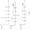
- FIG.19 illustrates a state where each spectral coefficient is perceptually weighted.
- spectral coefficient S(f1) in FIG. 19 shows that this spectral coefficient has a larger amplitude value than other spectral coefficients.
- signal-to-noise ratio SNR(f1) at frequency f1 is a maximum value in comparison with other signal-to-noise ratios.
- the present embodiment multiplies a small weighting coefficient W(f1) which is less than 1 to spectral coefficient S e (f1) of an error signal, and hence the amplitude value of weighted spectral coefficient S e_PW (f1) becomes smaller than that of S e (f1).
- perceptually-weighted spectral coefficient S e_PW (f1) is represented as the following equation, to reveal that S e_PW (f1) becomes lower than spectral coefficient S e (f1).
- the present embodiment lowers the importance of the spectrum with a high signal-to-noise ratio to set coding bits less likely to be distributed to this spectrum.
- Each function block employed in the description of each of the aforementioned embodiments may typically be implemented as an LSI constituted by an integrated circuit. These may be individual chips or partially or totally contained on a single chip. "LSI” is adopted here but this may also be referred to as “IC,” “system LSI,” “super LSI,” or “ultra LSI” depending on differing extents of integration.
- the method of implementing integrated circuitry is not limited to LSI, and implementation by means of dedicated circuitry or a general-purpose processor may also be used. After LSI manufacture, utilization of a programmable FPGA (Field Programmable Gate Array) or a reconfigurable processor where connections and settings of circuit cells within an LSI can be reconfigured is also possible.
- a programmable FPGA Field Programmable Gate Array
- a reconfigurable processor where connections and settings of circuit cells within an LSI can be reconfigured is also possible.
- the present invention is suitable for a communication apparatus encoding speech.
Landscapes
- Engineering & Computer Science (AREA)
- Physics & Mathematics (AREA)
- Computational Linguistics (AREA)
- Signal Processing (AREA)
- Health & Medical Sciences (AREA)
- Audiology, Speech & Language Pathology (AREA)
- Human Computer Interaction (AREA)
- Acoustics & Sound (AREA)
- Multimedia (AREA)
- Spectroscopy & Molecular Physics (AREA)
- Quality & Reliability (AREA)
- Compression, Expansion, Code Conversion, And Decoders (AREA)
Claims (2)
- Appareil de codage vocal (1600A) adapté pour mettre en oeuvre un codage par couches incluant au moins deux couches parmi une couche inférieure et une couche supérieure, l'appareil de codage vocal comprenant :une section de génération (1612) adaptée pour générer un signal d'erreur entre un signal décodé de la couche inférieure et un signal d'entrée ;une section d'estimation (1801) adaptée pour calculer un rapport signal sur bruit en utilisant le signal d'entrée et le signal d'erreur et adaptée pour estimer (1802) des niveaux d'importance perceptuelle respectifs d'une pluralité de coefficients spectraux de différentes fréquences dans le signal d'erreur, sur base du rapport signal sur bruit ;une section de calcul (1803) adaptée pour calculer des coefficients de pondération respectifs de la pluralité de coefficients spectraux sur base des niveaux d'importance estimés respectifs ;une section de pondération (1804) adaptée pour pondérer chaque coefficient de la pluralité de coefficients spectraux en utilisant les coefficients de pondération calculés respectifs ; etune section de codage (1606) adaptée pour coder la pluralité de coefficients spectraux pondérés.
- Procédé de codage vocal pour mettre en oeuvre un codage par couches incluant au moins deux couches parmi une couche inférieure et une couche supérieure, le procédé de codage vocal comprenant les étapes suivantes :génération d'un signal d'erreur entre un signal décodé de la couche inférieure et un signal d'entrée ;calcul d'un rapport signal sur bruit en utilisant le signal d'entrée et le signal d'erreur et estimation des niveaux d'importance perceptuelle respectifs d'une pluralité de coefficients spectraux de différentes fréquences dans le signal d'erreur, sur base du rapport signal sur bruit ;calcul des coefficients de pondération respectifs de la pluralité de coefficients spectraux sur base des niveaux d'importance estimés respectifs ;pondération de chaque coefficient de la pluralité de coefficients spectraux en utilisant les coefficients de pondération calculés respectifs ; etcodage de la pluralité de coefficients spectraux pondérés.
Applications Claiming Priority (2)
| Application Number | Priority Date | Filing Date | Title |
|---|---|---|---|
| JP2010006312 | 2010-01-14 | ||
| PCT/JP2011/000134 WO2011086924A1 (fr) | 2010-01-14 | 2011-01-13 | Appareil de codage audio et procédé de codage audio |
Publications (3)
| Publication Number | Publication Date |
|---|---|
| EP2525355A1 EP2525355A1 (fr) | 2012-11-21 |
| EP2525355A4 EP2525355A4 (fr) | 2016-11-02 |
| EP2525355B1 true EP2525355B1 (fr) | 2017-11-01 |
Family
ID=44304200
Family Applications (1)
| Application Number | Title | Priority Date | Filing Date |
|---|---|---|---|
| EP11732797.3A Not-in-force EP2525355B1 (fr) | 2010-01-14 | 2011-01-13 | Appareil de codage audio et procédé de codage audio |
Country Status (4)
| Country | Link |
|---|---|
| US (1) | US20130030796A1 (fr) |
| EP (1) | EP2525355B1 (fr) |
| JP (1) | JP5809066B2 (fr) |
| WO (1) | WO2011086924A1 (fr) |
Families Citing this family (12)
| Publication number | Priority date | Publication date | Assignee | Title |
|---|---|---|---|---|
| CN102081927B (zh) * | 2009-11-27 | 2012-07-18 | 中兴通讯股份有限公司 | 一种可分层音频编码、解码方法及系统 |
| PL3232437T3 (pl) | 2012-12-13 | 2019-05-31 | Fraunhofer Ges Forschung | Urządzenie do kodowania głosowego audio, urządzenie do dekodowania głosowego audio, sposób kodowania głosowego audio i sposób dekodowania głosowego audio |
| ES2836194T3 (es) * | 2013-06-11 | 2021-06-24 | Fraunhofer Ges Forschung | Dispositivo y procedimiento para la extensión de ancho de banda para señales acústicas |
| WO2015037969A1 (fr) * | 2013-09-16 | 2015-03-19 | 삼성전자 주식회사 | Procédé et dispositif de codage de signal et procédé et dispositif de décodage de signal |
| CN110867190B (zh) | 2013-09-16 | 2023-10-13 | 三星电子株式会社 | 信号编码方法和装置以及信号解码方法和装置 |
| CN105814856B (zh) * | 2013-11-26 | 2019-02-12 | 普鲁斯恩公司 | 控制组合波形的方法、设备和系统、组合多个信号的设备 |
| AU2014360038B2 (en) | 2013-12-02 | 2017-11-02 | Huawei Technologies Co., Ltd. | Encoding method and apparatus |
| TWI569257B (zh) * | 2014-07-04 | 2017-02-01 | 玄舟科技有限公司 | 音訊處理裝置及其音訊處理方法 |
| CA2958429C (fr) | 2014-07-25 | 2020-03-10 | Panasonic Intellectual Property Corporation Of America | Appareil de codage de signal audio, appareil de decodage de signal audio, methode de codage de signal audio et methode de decodage de signal audio |
| PT3413307T (pt) * | 2014-07-25 | 2020-10-19 | Fraunhofer Ges Forschung | Aparelho de codificação de sinal de áudio, dispositivo de descodificação de sinal de áudio, e seus métodos |
| CN106448688B (zh) * | 2014-07-28 | 2019-11-05 | 华为技术有限公司 | 音频编码方法及相关装置 |
| JP7150996B2 (ja) * | 2019-01-13 | 2022-10-11 | 華為技術有限公司 | ハイレゾリューションオーディオ符号化 |
Family Cites Families (16)
| Publication number | Priority date | Publication date | Assignee | Title |
|---|---|---|---|---|
| JP3246715B2 (ja) * | 1996-07-01 | 2002-01-15 | 松下電器産業株式会社 | オーディオ信号圧縮方法,およびオーディオ信号圧縮装置 |
| JP3616307B2 (ja) * | 2000-05-22 | 2005-02-02 | 日本電信電話株式会社 | 音声・楽音信号符号化方法及びこの方法を実行するプログラムを記録した記録媒体 |
| US7240001B2 (en) * | 2001-12-14 | 2007-07-03 | Microsoft Corporation | Quality improvement techniques in an audio encoder |
| US7146313B2 (en) * | 2001-12-14 | 2006-12-05 | Microsoft Corporation | Techniques for measurement of perceptual audio quality |
| JP4734859B2 (ja) * | 2004-06-28 | 2011-07-27 | ソニー株式会社 | 信号符号化装置及び方法、並びに信号復号装置及び方法 |
| US7725313B2 (en) * | 2004-09-13 | 2010-05-25 | Ittiam Systems (P) Ltd. | Method, system and apparatus for allocating bits in perceptual audio coders |
| MX2007005261A (es) * | 2004-11-04 | 2007-07-09 | Koninkl Philips Electronics Nv | Codificacion y descodificacion de un conjunto de senales. |
| KR100707173B1 (ko) * | 2004-12-21 | 2007-04-13 | 삼성전자주식회사 | 저비트율 부호화/복호화방법 및 장치 |
| EP1840874B1 (fr) * | 2005-01-11 | 2019-04-10 | NEC Corporation | Dispositif de codage audio, methode de codage audio et programme de codage audio |
| KR100851970B1 (ko) * | 2005-07-15 | 2008-08-12 | 삼성전자주식회사 | 오디오 신호의 중요주파수 성분 추출방법 및 장치와 이를이용한 저비트율 오디오 신호 부호화/복호화 방법 및 장치 |
| JP4548348B2 (ja) * | 2006-01-18 | 2010-09-22 | カシオ計算機株式会社 | 音声符号化装置及び音声符号化方法 |
| US8046218B2 (en) * | 2006-09-19 | 2011-10-25 | The Board Of Trustees Of The University Of Illinois | Speech and method for identifying perceptual features |
| EP2193348A1 (fr) * | 2007-09-28 | 2010-06-09 | Voiceage Corporation | Procédé et dispositif pour une quantification efficace d'informations de transformée dans un codec de parole et d'audio incorporé |
| US8515767B2 (en) * | 2007-11-04 | 2013-08-20 | Qualcomm Incorporated | Technique for encoding/decoding of codebook indices for quantized MDCT spectrum in scalable speech and audio codecs |
| JP5508692B2 (ja) | 2008-06-30 | 2014-06-04 | 日本プラスト株式会社 | フェンダープロテクタを取付けた車両 |
| FR2947944A1 (fr) * | 2009-07-07 | 2011-01-14 | France Telecom | Codage/decodage perfectionne de signaux audionumeriques |
-
2011
- 2011-01-13 US US13/521,590 patent/US20130030796A1/en not_active Abandoned
- 2011-01-13 EP EP11732797.3A patent/EP2525355B1/fr not_active Not-in-force
- 2011-01-13 JP JP2011549936A patent/JP5809066B2/ja not_active Expired - Fee Related
- 2011-01-13 WO PCT/JP2011/000134 patent/WO2011086924A1/fr not_active Ceased
Non-Patent Citations (1)
| Title |
|---|
| None * |
Also Published As
| Publication number | Publication date |
|---|---|
| EP2525355A4 (fr) | 2016-11-02 |
| JPWO2011086924A1 (ja) | 2013-05-16 |
| EP2525355A1 (fr) | 2012-11-21 |
| US20130030796A1 (en) | 2013-01-31 |
| JP5809066B2 (ja) | 2015-11-10 |
| WO2011086924A1 (fr) | 2011-07-21 |
Similar Documents
| Publication | Publication Date | Title |
|---|---|---|
| EP2525355B1 (fr) | Appareil de codage audio et procédé de codage audio | |
| JP6170520B2 (ja) | オーディオ及び/またはスピーチ信号符号化及び/または復号化方法及び装置 | |
| KR101411901B1 (ko) | 오디오 신호의 부호화/복호화 방법 및 장치 | |
| EP2320416B1 (fr) | Dispositif de lissage spectral, dispositif de codage, dispositif de décodage, dispositif de terminal de communication, dispositif de station de base et procédé de lissage spectral | |
| JP5695074B2 (ja) | 音声符号化装置および音声復号化装置 | |
| EP2814028B1 (fr) | Dispositif de codage audio et vocal, dispositif de décodage audio et vocal, procédé de codage audio et vocal, et procédé de décodage audio et vocal | |
| EP2133872B1 (fr) | Dispositif et procédé de codage | |
| EP2772912B1 (fr) | Appareil de codage audio, appareil de décodage audio, procédé de codage audio et procédé de décodage audio | |
| CN103548080A (zh) | 声音信号混合编码器、声音信号混合解码器、声音信号编码方法以及声音信号解码方法 | |
| EP1801785A1 (fr) | Codeur modulable, decodeur modulable et methode de codage modulable | |
| US9390722B2 (en) | Method and device for quantizing voice signals in a band-selective manner | |
| JPWO2012004998A1 (ja) | スペクトル係数コーディングの量子化パラメータを効率的に符号化する装置及び方法 | |
| Ganapathy et al. | Autoregressive Modelling of Hilbert Envelopes for Wide-band Audio Coding | |
| KR101434206B1 (ko) | 신호 복호화 장치 | |
| KR101434209B1 (ko) | 오디오/스피치 신호 부호화장치 | |
| KR101434207B1 (ko) | 오디오/스피치 신호 부호화방법 | |
| Motlicek et al. | Wide-band audio coding based on frequency-domain linear prediction |
Legal Events
| Date | Code | Title | Description |
|---|---|---|---|
| PUAI | Public reference made under article 153(3) epc to a published international application that has entered the european phase |
Free format text: ORIGINAL CODE: 0009012 |
|
| 17P | Request for examination filed |
Effective date: 20120711 |
|
| AK | Designated contracting states |
Kind code of ref document: A1 Designated state(s): AL AT BE BG CH CY CZ DE DK EE ES FI FR GB GR HR HU IE IS IT LI LT LU LV MC MK MT NL NO PL PT RO RS SE SI SK SM TR |
|
| DAX | Request for extension of the european patent (deleted) | ||
| RAP1 | Party data changed (applicant data changed or rights of an application transferred) |
Owner name: PANASONIC INTELLECTUAL PROPERTY CORPORATION OF AME |
|
| RA4 | Supplementary search report drawn up and despatched (corrected) |
Effective date: 20161006 |
|
| RIC1 | Information provided on ipc code assigned before grant |
Ipc: G10L 19/24 20130101ALI20160929BHEP Ipc: G10L 19/12 20130101ALN20160929BHEP Ipc: G10L 19/02 20130101AFI20160929BHEP |
|
| GRAP | Despatch of communication of intention to grant a patent |
Free format text: ORIGINAL CODE: EPIDOSNIGR1 |
|
| STAA | Information on the status of an ep patent application or granted ep patent |
Free format text: STATUS: GRANT OF PATENT IS INTENDED |
|
| RIC1 | Information provided on ipc code assigned before grant |
Ipc: G10L 19/12 20130101ALN20170427BHEP Ipc: G10L 19/02 20130101AFI20170427BHEP Ipc: G10L 19/24 20130101ALI20170427BHEP |
|
| INTG | Intention to grant announced |
Effective date: 20170531 |
|
| GRAS | Grant fee paid |
Free format text: ORIGINAL CODE: EPIDOSNIGR3 |
|
| GRAA | (expected) grant |
Free format text: ORIGINAL CODE: 0009210 |
|
| STAA | Information on the status of an ep patent application or granted ep patent |
Free format text: STATUS: THE PATENT HAS BEEN GRANTED |
|
| AK | Designated contracting states |
Kind code of ref document: B1 Designated state(s): AL AT BE BG CH CY CZ DE DK EE ES FI FR GB GR HR HU IE IS IT LI LT LU LV MC MK MT NL NO PL PT RO RS SE SI SK SM TR |
|
| REG | Reference to a national code |
Ref country code: GB Ref legal event code: FG4D |
|
| REG | Reference to a national code |
Ref country code: CH Ref legal event code: EP Ref country code: AT Ref legal event code: REF Ref document number: 942765 Country of ref document: AT Kind code of ref document: T Effective date: 20171115 |
|
| REG | Reference to a national code |
Ref country code: IE Ref legal event code: FG4D |
|
| REG | Reference to a national code |
Ref country code: DE Ref legal event code: R096 Ref document number: 602011042901 Country of ref document: DE |
|
| REG | Reference to a national code |
Ref country code: NL Ref legal event code: MP Effective date: 20171101 |
|
| REG | Reference to a national code |
Ref country code: LT Ref legal event code: MG4D |
|
| REG | Reference to a national code |
Ref country code: AT Ref legal event code: MK05 Ref document number: 942765 Country of ref document: AT Kind code of ref document: T Effective date: 20171101 |
|
| PG25 | Lapsed in a contracting state [announced via postgrant information from national office to epo] |
Ref country code: FI Free format text: LAPSE BECAUSE OF FAILURE TO SUBMIT A TRANSLATION OF THE DESCRIPTION OR TO PAY THE FEE WITHIN THE PRESCRIBED TIME-LIMIT Effective date: 20171101 Ref country code: NL Free format text: LAPSE BECAUSE OF FAILURE TO SUBMIT A TRANSLATION OF THE DESCRIPTION OR TO PAY THE FEE WITHIN THE PRESCRIBED TIME-LIMIT Effective date: 20171101 Ref country code: LT Free format text: LAPSE BECAUSE OF FAILURE TO SUBMIT A TRANSLATION OF THE DESCRIPTION OR TO PAY THE FEE WITHIN THE PRESCRIBED TIME-LIMIT Effective date: 20171101 Ref country code: SE Free format text: LAPSE BECAUSE OF FAILURE TO SUBMIT A TRANSLATION OF THE DESCRIPTION OR TO PAY THE FEE WITHIN THE PRESCRIBED TIME-LIMIT Effective date: 20171101 Ref country code: ES Free format text: LAPSE BECAUSE OF FAILURE TO SUBMIT A TRANSLATION OF THE DESCRIPTION OR TO PAY THE FEE WITHIN THE PRESCRIBED TIME-LIMIT Effective date: 20171101 Ref country code: NO Free format text: LAPSE BECAUSE OF FAILURE TO SUBMIT A TRANSLATION OF THE DESCRIPTION OR TO PAY THE FEE WITHIN THE PRESCRIBED TIME-LIMIT Effective date: 20180201 |
|
| PG25 | Lapsed in a contracting state [announced via postgrant information from national office to epo] |
Ref country code: IS Free format text: LAPSE BECAUSE OF FAILURE TO SUBMIT A TRANSLATION OF THE DESCRIPTION OR TO PAY THE FEE WITHIN THE PRESCRIBED TIME-LIMIT Effective date: 20180301 Ref country code: LV Free format text: LAPSE BECAUSE OF FAILURE TO SUBMIT A TRANSLATION OF THE DESCRIPTION OR TO PAY THE FEE WITHIN THE PRESCRIBED TIME-LIMIT Effective date: 20171101 Ref country code: AT Free format text: LAPSE BECAUSE OF FAILURE TO SUBMIT A TRANSLATION OF THE DESCRIPTION OR TO PAY THE FEE WITHIN THE PRESCRIBED TIME-LIMIT Effective date: 20171101 Ref country code: RS Free format text: LAPSE BECAUSE OF FAILURE TO SUBMIT A TRANSLATION OF THE DESCRIPTION OR TO PAY THE FEE WITHIN THE PRESCRIBED TIME-LIMIT Effective date: 20171101 Ref country code: GR Free format text: LAPSE BECAUSE OF FAILURE TO SUBMIT A TRANSLATION OF THE DESCRIPTION OR TO PAY THE FEE WITHIN THE PRESCRIBED TIME-LIMIT Effective date: 20180202 Ref country code: HR Free format text: LAPSE BECAUSE OF FAILURE TO SUBMIT A TRANSLATION OF THE DESCRIPTION OR TO PAY THE FEE WITHIN THE PRESCRIBED TIME-LIMIT Effective date: 20171101 Ref country code: BG Free format text: LAPSE BECAUSE OF FAILURE TO SUBMIT A TRANSLATION OF THE DESCRIPTION OR TO PAY THE FEE WITHIN THE PRESCRIBED TIME-LIMIT Effective date: 20180201 |
|
| PG25 | Lapsed in a contracting state [announced via postgrant information from national office to epo] |
Ref country code: CY Free format text: LAPSE BECAUSE OF FAILURE TO SUBMIT A TRANSLATION OF THE DESCRIPTION OR TO PAY THE FEE WITHIN THE PRESCRIBED TIME-LIMIT Effective date: 20171101 Ref country code: EE Free format text: LAPSE BECAUSE OF FAILURE TO SUBMIT A TRANSLATION OF THE DESCRIPTION OR TO PAY THE FEE WITHIN THE PRESCRIBED TIME-LIMIT Effective date: 20171101 Ref country code: DK Free format text: LAPSE BECAUSE OF FAILURE TO SUBMIT A TRANSLATION OF THE DESCRIPTION OR TO PAY THE FEE WITHIN THE PRESCRIBED TIME-LIMIT Effective date: 20171101 Ref country code: SK Free format text: LAPSE BECAUSE OF FAILURE TO SUBMIT A TRANSLATION OF THE DESCRIPTION OR TO PAY THE FEE WITHIN THE PRESCRIBED TIME-LIMIT Effective date: 20171101 Ref country code: CZ Free format text: LAPSE BECAUSE OF FAILURE TO SUBMIT A TRANSLATION OF THE DESCRIPTION OR TO PAY THE FEE WITHIN THE PRESCRIBED TIME-LIMIT Effective date: 20171101 |
|
| REG | Reference to a national code |
Ref country code: DE Ref legal event code: R097 Ref document number: 602011042901 Country of ref document: DE |
|
| PG25 | Lapsed in a contracting state [announced via postgrant information from national office to epo] |
Ref country code: SM Free format text: LAPSE BECAUSE OF FAILURE TO SUBMIT A TRANSLATION OF THE DESCRIPTION OR TO PAY THE FEE WITHIN THE PRESCRIBED TIME-LIMIT Effective date: 20171101 Ref country code: IT Free format text: LAPSE BECAUSE OF FAILURE TO SUBMIT A TRANSLATION OF THE DESCRIPTION OR TO PAY THE FEE WITHIN THE PRESCRIBED TIME-LIMIT Effective date: 20171101 Ref country code: RO Free format text: LAPSE BECAUSE OF FAILURE TO SUBMIT A TRANSLATION OF THE DESCRIPTION OR TO PAY THE FEE WITHIN THE PRESCRIBED TIME-LIMIT Effective date: 20171101 Ref country code: PL Free format text: LAPSE BECAUSE OF FAILURE TO SUBMIT A TRANSLATION OF THE DESCRIPTION OR TO PAY THE FEE WITHIN THE PRESCRIBED TIME-LIMIT Effective date: 20171101 |
|
| REG | Reference to a national code |
Ref country code: CH Ref legal event code: PL |
|
| PLBE | No opposition filed within time limit |
Free format text: ORIGINAL CODE: 0009261 |
|
| STAA | Information on the status of an ep patent application or granted ep patent |
Free format text: STATUS: NO OPPOSITION FILED WITHIN TIME LIMIT |
|
| 26N | No opposition filed |
Effective date: 20180802 |
|
| GBPC | Gb: european patent ceased through non-payment of renewal fee |
Effective date: 20180201 |
|
| PG25 | Lapsed in a contracting state [announced via postgrant information from national office to epo] |
Ref country code: FR Free format text: LAPSE BECAUSE OF NON-PAYMENT OF DUE FEES Effective date: 20180131 Ref country code: LU Free format text: LAPSE BECAUSE OF NON-PAYMENT OF DUE FEES Effective date: 20180113 |
|
| REG | Reference to a national code |
Ref country code: IE Ref legal event code: MM4A |
|
| REG | Reference to a national code |
Ref country code: FR Ref legal event code: ST Effective date: 20180928 |
|
| REG | Reference to a national code |
Ref country code: BE Ref legal event code: MM Effective date: 20180131 |
|
| PG25 | Lapsed in a contracting state [announced via postgrant information from national office to epo] |
Ref country code: SI Free format text: LAPSE BECAUSE OF FAILURE TO SUBMIT A TRANSLATION OF THE DESCRIPTION OR TO PAY THE FEE WITHIN THE PRESCRIBED TIME-LIMIT Effective date: 20171101 Ref country code: BE Free format text: LAPSE BECAUSE OF NON-PAYMENT OF DUE FEES Effective date: 20180131 Ref country code: CH Free format text: LAPSE BECAUSE OF NON-PAYMENT OF DUE FEES Effective date: 20180131 Ref country code: LI Free format text: LAPSE BECAUSE OF NON-PAYMENT OF DUE FEES Effective date: 20180131 |
|
| PG25 | Lapsed in a contracting state [announced via postgrant information from national office to epo] |
Ref country code: IE Free format text: LAPSE BECAUSE OF NON-PAYMENT OF DUE FEES Effective date: 20180113 |
|
| PG25 | Lapsed in a contracting state [announced via postgrant information from national office to epo] |
Ref country code: GB Free format text: LAPSE BECAUSE OF NON-PAYMENT OF DUE FEES Effective date: 20180201 |
|
| PG25 | Lapsed in a contracting state [announced via postgrant information from national office to epo] |
Ref country code: MC Free format text: LAPSE BECAUSE OF FAILURE TO SUBMIT A TRANSLATION OF THE DESCRIPTION OR TO PAY THE FEE WITHIN THE PRESCRIBED TIME-LIMIT Effective date: 20171101 |
|
| PG25 | Lapsed in a contracting state [announced via postgrant information from national office to epo] |
Ref country code: MT Free format text: LAPSE BECAUSE OF NON-PAYMENT OF DUE FEES Effective date: 20180113 |
|
| PG25 | Lapsed in a contracting state [announced via postgrant information from national office to epo] |
Ref country code: TR Free format text: LAPSE BECAUSE OF FAILURE TO SUBMIT A TRANSLATION OF THE DESCRIPTION OR TO PAY THE FEE WITHIN THE PRESCRIBED TIME-LIMIT Effective date: 20171101 |
|
| PG25 | Lapsed in a contracting state [announced via postgrant information from national office to epo] |
Ref country code: HU Free format text: LAPSE BECAUSE OF FAILURE TO SUBMIT A TRANSLATION OF THE DESCRIPTION OR TO PAY THE FEE WITHIN THE PRESCRIBED TIME-LIMIT; INVALID AB INITIO Effective date: 20110113 Ref country code: PT Free format text: LAPSE BECAUSE OF FAILURE TO SUBMIT A TRANSLATION OF THE DESCRIPTION OR TO PAY THE FEE WITHIN THE PRESCRIBED TIME-LIMIT Effective date: 20171101 |
|
| PG25 | Lapsed in a contracting state [announced via postgrant information from national office to epo] |
Ref country code: MK Free format text: LAPSE BECAUSE OF NON-PAYMENT OF DUE FEES Effective date: 20171101 |
|
| PG25 | Lapsed in a contracting state [announced via postgrant information from national office to epo] |
Ref country code: AL Free format text: LAPSE BECAUSE OF FAILURE TO SUBMIT A TRANSLATION OF THE DESCRIPTION OR TO PAY THE FEE WITHIN THE PRESCRIBED TIME-LIMIT Effective date: 20171101 |
|
| PGFP | Annual fee paid to national office [announced via postgrant information from national office to epo] |
Ref country code: DE Payment date: 20240119 Year of fee payment: 14 |
|
| REG | Reference to a national code |
Ref country code: DE Ref legal event code: R119 Ref document number: 602011042901 Country of ref document: DE |
|
| PG25 | Lapsed in a contracting state [announced via postgrant information from national office to epo] |
Ref country code: DE Free format text: LAPSE BECAUSE OF NON-PAYMENT OF DUE FEES Effective date: 20250801 |