EP2525430A1 - Cellule d'humidification ayant un tissu de support consistant de polymère fluoré - Google Patents
Cellule d'humidification ayant un tissu de support consistant de polymère fluoré Download PDFInfo
- Publication number
- EP2525430A1 EP2525430A1 EP11166699A EP11166699A EP2525430A1 EP 2525430 A1 EP2525430 A1 EP 2525430A1 EP 11166699 A EP11166699 A EP 11166699A EP 11166699 A EP11166699 A EP 11166699A EP 2525430 A1 EP2525430 A1 EP 2525430A1
- Authority
- EP
- European Patent Office
- Prior art keywords
- outer plate
- membrane
- cell
- water
- humidification
- Prior art date
- Legal status (The legal status is an assumption and is not a legal conclusion. Google has not performed a legal analysis and makes no representation as to the accuracy of the status listed.)
- Withdrawn
Links
- 229920002313 fluoropolymer Polymers 0.000 title claims abstract description 11
- 239000004811 fluoropolymer Substances 0.000 title 1
- 239000012528 membrane Substances 0.000 claims abstract description 58
- 239000000446 fuel Substances 0.000 claims abstract description 49
- XLYOFNOQVPJJNP-UHFFFAOYSA-N water Substances O XLYOFNOQVPJJNP-UHFFFAOYSA-N 0.000 claims abstract description 42
- 239000004744 fabric Substances 0.000 claims abstract description 25
- VGGSQFUCUMXWEO-UHFFFAOYSA-N Ethene Chemical compound C=C VGGSQFUCUMXWEO-UHFFFAOYSA-N 0.000 claims abstract description 4
- 239000005977 Ethylene Substances 0.000 claims abstract description 4
- UUAGAQFQZIEFAH-UHFFFAOYSA-N chlorotrifluoroethylene Chemical group FC(F)=C(F)Cl UUAGAQFQZIEFAH-UHFFFAOYSA-N 0.000 claims abstract description 4
- 239000011148 porous material Substances 0.000 claims description 7
- 238000003490 calendering Methods 0.000 claims description 4
- 239000007788 liquid Substances 0.000 abstract description 9
- 229920005603 alternating copolymer Polymers 0.000 abstract description 3
- 230000001052 transient effect Effects 0.000 abstract description 2
- 239000007789 gas Substances 0.000 description 40
- OKTJSMMVPCPJKN-UHFFFAOYSA-N Carbon Chemical compound [C] OKTJSMMVPCPJKN-UHFFFAOYSA-N 0.000 description 15
- 229910052799 carbon Inorganic materials 0.000 description 15
- 239000002737 fuel gas Substances 0.000 description 8
- 239000002184 metal Substances 0.000 description 5
- QVGXLLKOCUKJST-UHFFFAOYSA-N atomic oxygen Chemical compound [O] QVGXLLKOCUKJST-UHFFFAOYSA-N 0.000 description 4
- 239000008236 heating water Substances 0.000 description 4
- 238000005259 measurement Methods 0.000 description 4
- 239000001301 oxygen Substances 0.000 description 4
- 229910052760 oxygen Inorganic materials 0.000 description 4
- 238000010276 construction Methods 0.000 description 2
- 230000007797 corrosion Effects 0.000 description 2
- 238000005260 corrosion Methods 0.000 description 2
- 239000003792 electrolyte Substances 0.000 description 2
- 238000010438 heat treatment Methods 0.000 description 2
- 239000001257 hydrogen Substances 0.000 description 2
- 229910052739 hydrogen Inorganic materials 0.000 description 2
- 239000000463 material Substances 0.000 description 2
- 238000009736 wetting Methods 0.000 description 2
- 229920000049 Carbon (fiber) Polymers 0.000 description 1
- UFHFLCQGNIYNRP-UHFFFAOYSA-N Hydrogen Chemical compound [H][H] UFHFLCQGNIYNRP-UHFFFAOYSA-N 0.000 description 1
- 239000004917 carbon fiber Substances 0.000 description 1
- 239000002131 composite material Substances 0.000 description 1
- 230000005494 condensation Effects 0.000 description 1
- 238000009833 condensation Methods 0.000 description 1
- 230000006735 deficit Effects 0.000 description 1
- 230000001419 dependent effect Effects 0.000 description 1
- 150000002431 hydrogen Chemical class 0.000 description 1
- 230000002706 hydrostatic effect Effects 0.000 description 1
- 230000014759 maintenance of location Effects 0.000 description 1
- 238000004519 manufacturing process Methods 0.000 description 1
- VNWKTOKETHGBQD-UHFFFAOYSA-N methane Chemical compound C VNWKTOKETHGBQD-UHFFFAOYSA-N 0.000 description 1
- 238000000034 method Methods 0.000 description 1
- 230000003647 oxidation Effects 0.000 description 1
- 238000007254 oxidation reaction Methods 0.000 description 1
- 239000005518 polymer electrolyte Substances 0.000 description 1
- 230000000284 resting effect Effects 0.000 description 1
- 229920006395 saturated elastomer Polymers 0.000 description 1
- 239000003566 sealing material Substances 0.000 description 1
Images


Classifications
-
- H—ELECTRICITY
- H01—ELECTRIC ELEMENTS
- H01M—PROCESSES OR MEANS, e.g. BATTERIES, FOR THE DIRECT CONVERSION OF CHEMICAL ENERGY INTO ELECTRICAL ENERGY
- H01M8/00—Fuel cells; Manufacture thereof
- H01M8/04—Auxiliary arrangements, e.g. for control of pressure or for circulation of fluids
- H01M8/04082—Arrangements for control of reactant parameters, e.g. pressure or concentration
- H01M8/04089—Arrangements for control of reactant parameters, e.g. pressure or concentration of gaseous reactants
- H01M8/04119—Arrangements for control of reactant parameters, e.g. pressure or concentration of gaseous reactants with simultaneous supply or evacuation of electrolyte; Humidifying or dehumidifying
- H01M8/04126—Humidifying
- H01M8/04149—Humidifying by diffusion, e.g. making use of membranes
-
- H—ELECTRICITY
- H01—ELECTRIC ELEMENTS
- H01M—PROCESSES OR MEANS, e.g. BATTERIES, FOR THE DIRECT CONVERSION OF CHEMICAL ENERGY INTO ELECTRICAL ENERGY
- H01M8/00—Fuel cells; Manufacture thereof
- H01M8/04—Auxiliary arrangements, e.g. for control of pressure or for circulation of fluids
- H01M8/04082—Arrangements for control of reactant parameters, e.g. pressure or concentration
- H01M8/04089—Arrangements for control of reactant parameters, e.g. pressure or concentration of gaseous reactants
- H01M8/04119—Arrangements for control of reactant parameters, e.g. pressure or concentration of gaseous reactants with simultaneous supply or evacuation of electrolyte; Humidifying or dehumidifying
- H01M8/04126—Humidifying
-
- H—ELECTRICITY
- H01—ELECTRIC ELEMENTS
- H01M—PROCESSES OR MEANS, e.g. BATTERIES, FOR THE DIRECT CONVERSION OF CHEMICAL ENERGY INTO ELECTRICAL ENERGY
- H01M8/00—Fuel cells; Manufacture thereof
- H01M8/10—Fuel cells with solid electrolytes
- H01M2008/1095—Fuel cells with polymeric electrolytes
-
- Y—GENERAL TAGGING OF NEW TECHNOLOGICAL DEVELOPMENTS; GENERAL TAGGING OF CROSS-SECTIONAL TECHNOLOGIES SPANNING OVER SEVERAL SECTIONS OF THE IPC; TECHNICAL SUBJECTS COVERED BY FORMER USPC CROSS-REFERENCE ART COLLECTIONS [XRACs] AND DIGESTS
- Y02—TECHNOLOGIES OR APPLICATIONS FOR MITIGATION OR ADAPTATION AGAINST CLIMATE CHANGE
- Y02E—REDUCTION OF GREENHOUSE GAS [GHG] EMISSIONS, RELATED TO ENERGY GENERATION, TRANSMISSION OR DISTRIBUTION
- Y02E60/00—Enabling technologies; Technologies with a potential or indirect contribution to GHG emissions mitigation
- Y02E60/30—Hydrogen technology
- Y02E60/50—Fuel cells
Definitions
- the invention relates to a humidification cell according to the preamble of patent claim 1;
- a humidification cell is for example from WO 2009/101036 A1 known.
- the fuel cells of a fuel cell assembly are supplied during their operation with operating gases - ie a hydrogen-containing fuel gas and an oxygen-containing oxidation gas.
- operating gases - ie a hydrogen-containing fuel gas and an oxygen-containing oxidation gas.
- Some embodiments of low-temperature fuel cells in particular fuel cells with a polymer electrolyte membrane (PEM fuel cell), require operating humidified operating gases. These operating gases are saturated with water vapor in a suitable device, such as a liquid ring compressor or a membrane humidifier.
- the humidifying device and any further supply devices together with the fuel cell arrangement form a fuel cell device.
- the temperature of a humidified operating gas can be reduced in this way by loss of heat to the environment decrease. This leads to the condensation of dampening water.
- the operating gases are then reheated in the fuel cells, thereby reducing their relative humidity. As a result, the always wet and extremely drought-sensitive electrolyte can be damaged, thereby reducing its life. It is therefore desirable that the humidifier is arranged as close as possible to the fuel cell.
- a fuel cell stack with a stack of planar fuel cells and a stack of planar humidification cells is known. Both stacks are arranged immediately adjacent in the fuel cell block.
- the moistening cells are designed as membrane moisteners in which, starting from a first outer plate, between the first outer plate and a second outer plate a gas space, a moistening water space and a water-permeable membrane separating the two spaces are arranged, wherein between the membrane and the first outer plate a water-permeable Support element is arranged.
- the operating gases Before the operating gases are supplied to the fuel cells of the fuel cell stack, they flow through the humidification cells where they are moistened and then flow into the fuel cell stack without leaving the fuel cell block.
- the dampening water flows and in the gas space, ie on the other side of the membrane, the operating gas flows through channels which are incorporated in the respective outer plate.
- a water-permeable support element is arranged between the membrane and one or both outer plates.
- the membrane in the region of the support element kept spaced from the outer plate and thus ensures that a large area humidifying water or operating gas can penetrate to the membrane, whereby the humidifying power is increased. This is especially important when using large-area structures in the outer panel.
- the dampening water either penetrates first the support element and then the membrane or first the membrane and then the support element and thus reaches the operating gas to be humidified.
- At least the support element between the membrane and the second outer plate is advantageously made of carbon paper.
- the carbon paper is stable against the operating media or membrane material used and preferably has hydrophilic properties, i. is completely wetted by the water.
- the carbon paper guarantees due to the hydrophilicity and the large surface, a good humidification and possible, caused by the hydrostatic pressure water droplets are distributed on the surface and taken in the gas space through the gas stream gaseous.
- the mechanical forces between the membrane and the outer plate (s) are well absorbed by the carbon paper, and direct contact between the membrane and the outer plate (s), and thus corrosion, is avoided.
- the humidification cell should be especially are also suitable for operation with a sudden change in the gas flow rate, as it is caused for example by load changes to the fuel cell.
- the fabric of the first support element consists of a fluoroplastic.
- such fabrics are characterized by good resistance to the operating gases of fuel cells (in particular to oxygen), a surface sufficiently large for gas humidification, and good retention / storage capacity for water (hydrophilicity).
- they can also be equipped with a very good wetting behavior for liquid water.
- a discharge and entrainment of liquid water during load changes or other transient operating conditions of the fuel cell, which are accompanied by a sudden change in the gas volume flow can be avoided.
- it is prevented that a part of the adhering to the surface of the tissue water is entrained in liquid form and passes from the humidifier area in the fuel cell, where there may be voltage dips.
- a second water-permeable support element is arranged between the membrane and the second outer panel, which is preferably also made of a fabric which consists of a fluoroplastic.
- the membrane can be held in a desired position particularly reliably.
- the fluoroplastic is calendered, i. produced by a calendering process.
- the good mechanical properties can be achieved, above all, when the fabric has a twill weave or a twill construction (also referred to for short as "twill” or "twill").
- the fabric has an air passage of 220 to 300 1 / m 2 s at 2 mbar, in particular of 260 1 / m 2 s at 2 mbar on.
- the fabric preferably has a thickness of 200 to 500 .mu.m, in particular of 370 .mu.m.
- the tissue is advantageous in terms of its thickness and the diameter of its pores to the stiffness of the membrane and the pressures in the adjoining the membrane rooms adapted such that during operation of the humidification even with load changes of the fuel cell, the membrane is not through the Pore squeezes and the outer plate touched.
- the fabric is then similar in spite of pores "dense" as a corresponding carbon paper.
- a particularly stable mounting of the membrane and a particularly simple construction of the humidification cell are achieved in that the first outer panel, the first support member, the membrane, the second support member and the second outer panel abut each other.
- the outer plates expediently have channels or embossments through which the operating gas or the dampening water can flow along the outer plate and along the support element resting against the outer plate.
- the humidification cell forms a particularly stable and largely insensitive to pressure composite.
- This embodiment of the invention is particularly suitable for very shallow humidification cells with a very shallow gas space and / or humidifying water space.
- the support element can completely cover the area of the membrane accessible to the dampening water or the operating gas. However, a good support of the membrane is also ensured if the support element, for example by recesses in the support element, covers only a part of the flat side of the membrane. This results in an unhindered access of dampening water and operating gas to the membrane, whereby the humidifying performance of the humidification cell is increased.
- FIG. 1 is a schematic plan view of the basic structure of a rectangular and planar humidification cell 1 is shown, which comprises a membrane 5 embedded in a frame of a sealing material 3 and shown cut open. Under the membrane 5, a support member 7 is also visible in cutaway view. Below the support element 7, an outer plate 9 is shown, which is designed as a sheet having an embossed structure 11. The embossed structure 11 consists of round elevations or depressions within the outer plate 9. Between the outer plate 9 and the support element 7, a covering device 13 is attached. The cover device 13 is arranged in the region of a resource inlet 15.
- FIG. 2 shows a section through the humidification cell 1 along the line II-II, but now on both sides of the membrane 5 are each a support member 7a and 7b and an outer plate 9a and 9b are arranged.
- the humidifying cell 1 includes a first outer plate 9a and a second outer plate 9b. Starting from the first outer plate 9a, a gas space 21, a humidifying water space 31 and the water-permeable membrane 5 separating the two spaces 21, 31 are arranged between the first outer plate 9a and the second outer plate 9b. Between the first outer plate 9a and the membrane 5 is a first water-permeable supporting element 7a and between the second outer plate 9b and the membrane 5, a second water-permeable supporting element 7b is arranged.
- the humidification cell 1 is part of a humidification cell stack of a fuel cell device.
- fuel gas flows through the axial passage 17 of the humidification cell 1.
- the axial passage 17 is aligned parallel to the stacking direction of the humidification cell stack.
- a respective radial channel 19 branches off to one of the moistening cells 1 of the moistening cell stack.
- the fuel gas flows through the radial passage 19 and in the further course through the operating medium inlet 15 and then enters the gas space 21 of the humidification cell 1. After exiting the operating medium inlet 15, the fuel gas passes without significant turbulence on the one hand on the cover 13 and on the other hand on the outer plate 9 of the humidification cell 1 along.
- the first outer plate 9a is configured as a heating element composed of two metal sheets. Between the metal sheets is a Schuwasserraum through which flows during operation of the humidification 1 warm heating water. This heating water heats both the fuel gas flowing through the humidification cell 1 and the humidifying water to approximately the temperature of the fuel cells of the fuel cell device.
- the fuel gas is moistened with dampening water and passes after flowing through the gas space 21 to the Radioffenauslass 23 of the gas space 21. Flowing through another radial channel and another axial channel it leaves the humidifying cell 1 again in the humidified state. Also in the area of the operating medium outlet 23, the supporting element 7a is covered by a further covering device 24 in order to prevent turbulence when the fuel gas flows into the operating medium outlet 23.
- FIG. 3 shows a section through the humidification cell 1 along the in FIG. 1 shown line III-III, wherein here on both sides of the membrane 5 are each a support member 7a and 7b and an outer plate 9a and 9b are arranged.
- This Section is taken along an axial channel 25, which leads 1 humidifying water during operation of the humidification.
- the humidifying water flows through the axial channel 25 and passes through the radial channel 27 to another resource inlet 29.
- This humidifying water flows into the Befeuchtungswasserraum 31 and flows between the second outer plate 9b and a covering device 33. Subsequently, the humidifying water passes to the second support member 7b ,
- the dampening water penetrates the second support element 7b and passes to the membrane 5. After passing through this water-permeable membrane 5, the dampening water also penetrates the first support element 7a arranged on the other side of the membrane 5. At the gas chamber 21 facing side of the support member 7a, the dampening water evaporates and thus moistens the fuel gas flowing through the gas space 21. Another part of the dampening water flows through the moistening water chamber 31 unused, sweeps along a further covering device 35 and leaves the moistening cell 1 again after flowing through a radial channel and a further axial channel.
- the second outer plate 9b is configured as a heating element composed of two metal sheets. Between the metal sheets is a Schuwasserraum through which flows during operation of the humidification 1 warm heating water. This heating water heats the humidifying water flowing through the humidifying water space 31 to approximately the temperature of the fuel cells of the fuel cell device.
- the two support elements 7a and 7b are detachably attached to the water-permeable membrane 5 and cover the flat outer sides of the membrane 5 to a narrow outer edge completely.
- the two support elements 7a and 7b, together with the membrane 5, form a membrane arrangement which is clamped between the two outer plates 9a, 9b of the humidification cell 1 is.
- the support elements 7a, 7b are thus on one side of the membrane 5 and on the other side on one of the outer plates 9a, 9b.
- the support elements 7a, 7b By the support elements 7a, 7b, the membrane 5 is held firmly in position.
- the support elements 7a, 7b cause that the membrane 5 at any point can not touch the outer plates 9a, 9b and thus is covered by a part of the outer plates 9a, 9b.
- the support elements 7a, 7b in this case consist of a fabric which has been produced from an alternating copolymer of ethylene and chlorotrifluoroethylene (E-CTFE) and calendered in the production process.
- the tissue has a twill weave.
- the fabric has an air passage of 220 to 300 1 / m 2 s at 2 mbar, in particular of 260 1 / m 2 s at 2 mbar, at a thickness of 200 to 500 .mu.m, in particular of 370 .mu.m.
- Such a fabric is available, for example, from the manufacturer Sefar under the name "Sefar Tetex® Mono 08-1050-K 039".
- the tissue in terms of its thickness and the diameter of its pores and the membrane are tuned with respect to each other in terms of their stiffness and the pressure in the adjoining the membrane spaces that the diaphragm does not force through the pores and the outer plate during operation of the humidification cell touched.
- FIG. 4 is a schematic representation of a fuel cell device 41 shown in the form of a fuel cell block.
- the fuel cell device 41 comprises a stack of humidification cells 43 and a stack of fuel cells 45.
- the humidification cells 43 have the same width and height as the fuel cells 45.
- the fuel cell block has a uniform along the stacking direction of the humidification cells 43 and the fuel cells 45 along a stack axis Width and height.
- the humidifying cells 43 have the same thickness as the fuel cells 45, so that the outer shape and the outer dimensions of the humidifying cells 43 are the same as the outer ones Shape and the outer dimensions of the fuel cells 45.
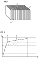
- FIG. 5 shows the humidifying power B at the outlet of a humidifier, consisting of 4 humidification cells, based on the gas flow G in fuel cell operation for a discharge pressure of 2.6 bara when using carbon paper K and when using a fabric E from E-CTFE.
- FIG. 6 Figure 11 shows a measurement of the pressure losses ⁇ p between humidifier inlet and outlet for a humidifier consisting of 4 humidification cells, based on gas stream G in fuel cell operation, for a 2.6 bara initial pressure using carbon paper K and using E-CTFE fabric E ,
- FIG. 7 shows the liquid water content F at the output of the humidifier at a load jump as a function of the operating time T before the load jump. How out FIG. 7 is apparent, the liquid water content F in the case of the fabric E of E-CTFE is significantly smaller than in the case of carbon paper K, the difference increases with operating times first and then remains relatively constant.
Landscapes
- Life Sciences & Earth Sciences (AREA)
- Engineering & Computer Science (AREA)
- Manufacturing & Machinery (AREA)
- Sustainable Development (AREA)
- Sustainable Energy (AREA)
- Chemical & Material Sciences (AREA)
- Chemical Kinetics & Catalysis (AREA)
- Electrochemistry (AREA)
- General Chemical & Material Sciences (AREA)
- Fuel Cell (AREA)
- Laminated Bodies (AREA)
Priority Applications (7)
| Application Number | Priority Date | Filing Date | Title |
|---|---|---|---|
| EP11166699A EP2525430A1 (fr) | 2011-05-19 | 2011-05-19 | Cellule d'humidification ayant un tissu de support consistant de polymère fluoré |
| EP12714703.1A EP2689486B1 (fr) | 2011-05-19 | 2012-04-16 | Cellule d'humidification |
| KR1020137030233A KR20140036183A (ko) | 2011-05-19 | 2012-04-16 | 가습 셀 |
| US14/118,616 US20140077402A1 (en) | 2011-05-19 | 2012-04-16 | Humidification cell |
| RU2013156341/07A RU2577033C2 (ru) | 2011-05-19 | 2012-04-16 | Увлажнительный элемент |
| ES12714703.1T ES2548835T3 (es) | 2011-05-19 | 2012-04-16 | Célula de humidificación |
| PCT/EP2012/056889 WO2012156160A1 (fr) | 2011-05-19 | 2012-04-16 | Cellule d'humidification |
Applications Claiming Priority (1)
| Application Number | Priority Date | Filing Date | Title |
|---|---|---|---|
| EP11166699A EP2525430A1 (fr) | 2011-05-19 | 2011-05-19 | Cellule d'humidification ayant un tissu de support consistant de polymère fluoré |
Publications (1)
| Publication Number | Publication Date |
|---|---|
| EP2525430A1 true EP2525430A1 (fr) | 2012-11-21 |
Family
ID=44766281
Family Applications (2)
| Application Number | Title | Priority Date | Filing Date |
|---|---|---|---|
| EP11166699A Withdrawn EP2525430A1 (fr) | 2011-05-19 | 2011-05-19 | Cellule d'humidification ayant un tissu de support consistant de polymère fluoré |
| EP12714703.1A Active EP2689486B1 (fr) | 2011-05-19 | 2012-04-16 | Cellule d'humidification |
Family Applications After (1)
| Application Number | Title | Priority Date | Filing Date |
|---|---|---|---|
| EP12714703.1A Active EP2689486B1 (fr) | 2011-05-19 | 2012-04-16 | Cellule d'humidification |
Country Status (6)
| Country | Link |
|---|---|
| US (1) | US20140077402A1 (fr) |
| EP (2) | EP2525430A1 (fr) |
| KR (1) | KR20140036183A (fr) |
| ES (1) | ES2548835T3 (fr) |
| RU (1) | RU2577033C2 (fr) |
| WO (1) | WO2012156160A1 (fr) |
Cited By (1)
| Publication number | Priority date | Publication date | Assignee | Title |
|---|---|---|---|---|
| DE102014003959B4 (de) * | 2014-03-20 | 2018-11-08 | Mann+Hummel Gmbh | Befeuchtungseinrichtung, beispielsweise für eine Brennstoffzelle |
Families Citing this family (3)
| Publication number | Priority date | Publication date | Assignee | Title |
|---|---|---|---|---|
| DE102015122144A1 (de) * | 2015-12-17 | 2017-06-22 | Volkswagen Ag | Befeuchter mit integriertem Wasserabscheider für ein Brennstoffzellensystem, Brennstoffzellensystem sowie Fahrzeug mit einem solchen |
| US10840521B2 (en) * | 2015-12-30 | 2020-11-17 | Mann+Hummel Gmbh | Humidifier, for example for a fuel cell |
| US12592403B2 (en) * | 2020-12-23 | 2026-03-31 | Kolon Industries, Inc. | Humidifier system for fuel cell |
Citations (5)
| Publication number | Priority date | Publication date | Assignee | Title |
|---|---|---|---|---|
| EP1298749A1 (fr) * | 2000-11-30 | 2003-04-02 | Siemens Aktiengesellschaft | Cellule d'humidification et installation de piles à combustible |
| US20070104987A1 (en) * | 2003-09-16 | 2007-05-10 | L' Air Liquide | Device for the transfer of water and heat between two air flows and use thereof for the humidification of fuel cell inlet gas |
| WO2009101036A1 (fr) | 2008-02-13 | 2009-08-20 | Siemens Aktiengesellschaft | Cellule d’humidification |
| JP2009238376A (ja) * | 2008-03-25 | 2009-10-15 | Equos Research Co Ltd | 燃料電池 |
| EP2139061A1 (fr) * | 2008-06-25 | 2009-12-30 | Siemens Aktiengesellschaft | Cellule d'humidification de membrane et dispositif de pile à combustible la contenant |
Family Cites Families (4)
| Publication number | Priority date | Publication date | Assignee | Title |
|---|---|---|---|---|
| JPWO2002059996A1 (ja) * | 2001-01-26 | 2004-05-27 | 東レ株式会社 | 高分子電解質膜およびその製造方法ならびにそれを用いた固体高分子型燃料電池 |
| ITMI20012379A1 (it) * | 2001-11-12 | 2003-05-12 | Uhdenora Technologies Srl | Cella di elettrolisi con elettrodi a diffusione di gas |
| DE102006036019A1 (de) * | 2006-08-02 | 2008-02-07 | Pemeas Gmbh | Membran-Elektroden-Einheit und Brennstoffzellen mit erhöhter Leistung |
| BRPI0922320A2 (pt) * | 2008-12-19 | 2016-01-05 | 3M Innovative Properties Co | material microporoso de um copolímero de etileno - cloro trifluoroetileno e método para a produção do mesmo |
-
2011
- 2011-05-19 EP EP11166699A patent/EP2525430A1/fr not_active Withdrawn
-
2012
- 2012-04-16 KR KR1020137030233A patent/KR20140036183A/ko not_active Ceased
- 2012-04-16 WO PCT/EP2012/056889 patent/WO2012156160A1/fr not_active Ceased
- 2012-04-16 EP EP12714703.1A patent/EP2689486B1/fr active Active
- 2012-04-16 RU RU2013156341/07A patent/RU2577033C2/ru not_active IP Right Cessation
- 2012-04-16 US US14/118,616 patent/US20140077402A1/en not_active Abandoned
- 2012-04-16 ES ES12714703.1T patent/ES2548835T3/es active Active
Patent Citations (7)
| Publication number | Priority date | Publication date | Assignee | Title |
|---|---|---|---|---|
| EP1298749A1 (fr) * | 2000-11-30 | 2003-04-02 | Siemens Aktiengesellschaft | Cellule d'humidification et installation de piles à combustible |
| EP1435121B1 (fr) | 2001-09-27 | 2005-05-04 | Siemens Aktiengesellschaft | Cellule d'humidification |
| US20070104987A1 (en) * | 2003-09-16 | 2007-05-10 | L' Air Liquide | Device for the transfer of water and heat between two air flows and use thereof for the humidification of fuel cell inlet gas |
| WO2009101036A1 (fr) | 2008-02-13 | 2009-08-20 | Siemens Aktiengesellschaft | Cellule d’humidification |
| US20100323251A1 (en) * | 2008-02-13 | 2010-12-23 | Siemens Aktiengesellschaft | Humidification cell |
| JP2009238376A (ja) * | 2008-03-25 | 2009-10-15 | Equos Research Co Ltd | 燃料電池 |
| EP2139061A1 (fr) * | 2008-06-25 | 2009-12-30 | Siemens Aktiengesellschaft | Cellule d'humidification de membrane et dispositif de pile à combustible la contenant |
Cited By (1)
| Publication number | Priority date | Publication date | Assignee | Title |
|---|---|---|---|---|
| DE102014003959B4 (de) * | 2014-03-20 | 2018-11-08 | Mann+Hummel Gmbh | Befeuchtungseinrichtung, beispielsweise für eine Brennstoffzelle |
Also Published As
| Publication number | Publication date |
|---|---|
| RU2013156341A (ru) | 2015-06-27 |
| RU2577033C2 (ru) | 2016-03-10 |
| EP2689486B1 (fr) | 2015-07-22 |
| EP2689486A1 (fr) | 2014-01-29 |
| KR20140036183A (ko) | 2014-03-25 |
| WO2012156160A1 (fr) | 2012-11-22 |
| ES2548835T3 (es) | 2015-10-21 |
| US20140077402A1 (en) | 2014-03-20 |
Similar Documents
| Publication | Publication Date | Title |
|---|---|---|
| DE112005001084B4 (de) | Gasseparator und Verfahren zu dessen Betrieb | |
| DE10102447B4 (de) | Befeuchter zur Verwendung mit einer Brennstoffzelle | |
| EP2243182B1 (fr) | Cellule d humidification | |
| DE102015122144A1 (de) | Befeuchter mit integriertem Wasserabscheider für ein Brennstoffzellensystem, Brennstoffzellensystem sowie Fahrzeug mit einem solchen | |
| DE19840517A1 (de) | Gasdiffusionsstruktur senkrecht zur Membran von Polymerelektrolyt-Membran Brennstoffzellen | |
| DE102008045732B4 (de) | Brennstoffzellenplatte sowie Brennstoffzellenanordnung | |
| EP1435121B1 (fr) | Cellule d'humidification | |
| DE102007055220B4 (de) | Brennstoffzellenanordnung | |
| DE102013208877A1 (de) | Befeuchter | |
| DE202011109654U1 (de) | Strömungsplattenverbund für Membranstapel | |
| EP2689486B1 (fr) | Cellule d'humidification | |
| DE102017201814A1 (de) | Strömungsplatte für einen Befeuchter | |
| DE102004058040B4 (de) | Brennstoffzelle | |
| EP2878029A1 (fr) | Dispositif d'humidification de gaz de process et système de pile à combustible le contenant | |
| DE102019126306A1 (de) | Brennstoffzellensystem | |
| DE19821985B4 (de) | Brennstoffzelle | |
| DE112010002746B4 (de) | Reaktionsschicht für Brennstoffzelle | |
| EP2139061A1 (fr) | Cellule d'humidification de membrane et dispositif de pile à combustible la contenant | |
| DE102020207581A1 (de) | Separator für brennstoffzelle | |
| WO2019141429A1 (fr) | Empilement de piles à combustible en cascade pourvu d'une gestion des eaux optimisée et système de piles à combustible | |
| WO2021151782A1 (fr) | Pile à combustible et système de piles à combustible | |
| DE102019211589A1 (de) | Befeuchter, Brennstoffzellenvorrichtung mit Befeuchter sowie Kraftfahrzeug | |
| DE102020111347A1 (de) | Feuchteübertragungsschicht, Speicherbefeuchter, Brennstoffzellenvorrichtung und Kraftfahrzeug | |
| DE102012011441A1 (de) | Membran-Elektroden-Einheit für eine Brennstoffzelle | |
| DE102019205815A1 (de) | Befeuchter, Brennstoffzellenvorrichtung und Verfahren zur Ermittlung und/oder Regulierung des Feuchtegehalts |
Legal Events
| Date | Code | Title | Description |
|---|---|---|---|
| PUAI | Public reference made under article 153(3) epc to a published international application that has entered the european phase |
Free format text: ORIGINAL CODE: 0009012 |
|
| AK | Designated contracting states |
Kind code of ref document: A1 Designated state(s): AL AT BE BG CH CY CZ DE DK EE ES FI FR GB GR HR HU IE IS IT LI LT LU LV MC MK MT NL NO PL PT RO RS SE SI SK SM TR |
|
| AX | Request for extension of the european patent |
Extension state: BA ME |
|
| RAP1 | Party data changed (applicant data changed or rights of an application transferred) |
Owner name: SIEMENS AKTIENGESELLSCHAFT |
|
| STAA | Information on the status of an ep patent application or granted ep patent |
Free format text: STATUS: THE APPLICATION IS DEEMED TO BE WITHDRAWN |
|
| 18D | Application deemed to be withdrawn |
Effective date: 20130522 |