EP2525748B1 - Einrichtung zur unterstützung der greiffunktion mit einer vorrichtung sowie einer befestigung der vorrichtung - Google Patents
Einrichtung zur unterstützung der greiffunktion mit einer vorrichtung sowie einer befestigung der vorrichtung Download PDFInfo
- Publication number
- EP2525748B1 EP2525748B1 EP11721225.8A EP11721225A EP2525748B1 EP 2525748 B1 EP2525748 B1 EP 2525748B1 EP 11721225 A EP11721225 A EP 11721225A EP 2525748 B1 EP2525748 B1 EP 2525748B1
- Authority
- EP
- European Patent Office
- Prior art keywords
- grippers
- aid tool
- tool
- aid
- activation
- Prior art date
- Legal status (The legal status is an assumption and is not a legal conclusion. Google has not performed a legal analysis and makes no representation as to the accuracy of the status listed.)
- Not-in-force
Links
Images




Classifications
-
- A—HUMAN NECESSITIES
- A61—MEDICAL OR VETERINARY SCIENCE; HYGIENE
- A61F—FILTERS IMPLANTABLE INTO BLOOD VESSELS; PROSTHESES; DEVICES PROVIDING PATENCY TO, OR PREVENTING COLLAPSING OF, TUBULAR STRUCTURES OF THE BODY, e.g. STENTS; ORTHOPAEDIC, NURSING OR CONTRACEPTIVE DEVICES; FOMENTATION; TREATMENT OR PROTECTION OF EYES OR EARS; BANDAGES, DRESSINGS OR ABSORBENT PADS; FIRST-AID KITS
- A61F2/00—Filters implantable into blood vessels; Prostheses, i.e. artificial substitutes or replacements for parts of the body; Appliances for connecting them with the body; Devices providing patency to, or preventing collapsing of, tubular structures of the body, e.g. stents
- A61F2/50—Prostheses not implantable in the body
- A61F2/54—Artificial arms or hands or parts thereof
- A61F2/58—Elbows; Wrists ; Other joints; Hands
- A61F2/583—Hands; Wrist joints
- A61F2/586—Fingers
-
- A—HUMAN NECESSITIES
- A61—MEDICAL OR VETERINARY SCIENCE; HYGIENE
- A61F—FILTERS IMPLANTABLE INTO BLOOD VESSELS; PROSTHESES; DEVICES PROVIDING PATENCY TO, OR PREVENTING COLLAPSING OF, TUBULAR STRUCTURES OF THE BODY, e.g. STENTS; ORTHOPAEDIC, NURSING OR CONTRACEPTIVE DEVICES; FOMENTATION; TREATMENT OR PROTECTION OF EYES OR EARS; BANDAGES, DRESSINGS OR ABSORBENT PADS; FIRST-AID KITS
- A61F2/00—Filters implantable into blood vessels; Prostheses, i.e. artificial substitutes or replacements for parts of the body; Appliances for connecting them with the body; Devices providing patency to, or preventing collapsing of, tubular structures of the body, e.g. stents
- A61F2/50—Prostheses not implantable in the body
- A61F2/68—Operating or control means
- A61F2/70—Operating or control means electrical
-
- A—HUMAN NECESSITIES
- A61—MEDICAL OR VETERINARY SCIENCE; HYGIENE
- A61F—FILTERS IMPLANTABLE INTO BLOOD VESSELS; PROSTHESES; DEVICES PROVIDING PATENCY TO, OR PREVENTING COLLAPSING OF, TUBULAR STRUCTURES OF THE BODY, e.g. STENTS; ORTHOPAEDIC, NURSING OR CONTRACEPTIVE DEVICES; FOMENTATION; TREATMENT OR PROTECTION OF EYES OR EARS; BANDAGES, DRESSINGS OR ABSORBENT PADS; FIRST-AID KITS
- A61F5/00—Orthopaedic methods or devices for non-surgical treatment of bones or joints; Nursing devices ; Anti-rape devices
- A61F5/01—Orthopaedic devices, e.g. long-term immobilising or pressure directing devices for treating broken or deformed bones such as splints, casts or braces
- A61F5/0102—Orthopaedic devices, e.g. long-term immobilising or pressure directing devices for treating broken or deformed bones such as splints, casts or braces specially adapted for correcting deformities of the limbs or for supporting them; Ortheses, e.g. with articulations
- A61F5/013—Orthopaedic devices, e.g. long-term immobilising or pressure directing devices for treating broken or deformed bones such as splints, casts or braces specially adapted for correcting deformities of the limbs or for supporting them; Ortheses, e.g. with articulations for the arms, hands or fingers
-
- B—PERFORMING OPERATIONS; TRANSPORTING
- B65—CONVEYING; PACKING; STORING; HANDLING THIN OR FILAMENTARY MATERIAL
- B65G—TRANSPORT OR STORAGE DEVICES, e.g. CONVEYORS FOR LOADING OR TIPPING, SHOP CONVEYOR SYSTEMS OR PNEUMATIC TUBE CONVEYORS
- B65G7/00—Devices for assisting manual moving or tilting heavy loads
- B65G7/12—Load carriers, e.g. hooks, slings, harness, gloves, modified for load carrying
Definitions
- This invention relates to aid devices for assisting people inhibited in their movement of especially the hands and / or wrists, such as people who are physically impaired due to arthritis, injury, or other physiological problems giving reduced strength.
- This is solved by introducing an aid tool with at least two grippers and means to attach each gripper to a finger of a person, where the grippers are adapted to follow the finger(s) in at least the directions to grab and release an object.
- an activation of the aid tool ensures a unidirectional locking of the grippers, meaning they are locked in their movement in the releasing direction.
- the invention further introduces mounting means for attaching the aid tool to a body part, where the mounting means comprises coupling means for detaching and attaching this and other tools according to the need.
- This invention relates to aid devices for assisting people inhibited in their movement of especially the hands and / or wrists, such as people who are physically impaired due to arthritis, injury, or other physiological problems giving reduced strength.
- tools for example such as a pen, pencil, or other writing instrument, scissors, toothbrushes, kitchen utensils (such as knives, forks, stirrers, spatulas, etc.), and the like.
- the aim of the present invention therefore is to introduce a device, either single-or multi-purpose aid device, which can assist or enable people with physically impaired hands and / or wrists to hold and use various hand-held tools and devices (such as toothbrushes, keys, scissors, tongs, and kitchen utensils) with greater ease, where the invention especially introduces a tool to assist gripping objects firmly, this being especially suited for users able to move their arms, hands and fingers, only having no strength to take a firm grip on objects.
- a device either single-or multi-purpose aid device, which can assist or enable people with physically impaired hands and / or wrists to hold and use various hand-held tools and devices (such as toothbrushes, keys, scissors, tongs, and kitchen utensils) with greater ease
- the invention especially introduces a tool to assist gripping objects firmly, this being especially suited for users able to move their arms, hands and fingers, only having no strength to take a firm grip on objects.
- a device with grippers to be placed between the user's fingers and an object to be held, so that the holding force exerted by the aid tool does not affect the fingers but only increases the pressure between the grippers of the aid tool and the object.
- WO 2008/036746 discloses a powered orthotic device including a brace having a first section and a second section being operationally coupled at a pivot.
- the device further includes at least one set of straps that removably attach the first section and the second section to a corresponding limb segment such that the pivot is proximate to a joint between each limb segment.
- the device also includes an electromyographic sensor and an actuator assembly in communication with the electromyographic sensor, and coupled to the first and second sections of the brace so as to apply a force for driving the first and second sections about the pivot, the force based on signals from the electromyographic sensor.
- US 4,167,044 discloses a means for actuating artificial or disabled arm members.
- a control mechanism may be used to control the operation of an artificial hand or a prosthesis attached to a disabled arm, in particular the fingers.
- a cable member extends from a finger-supporting portion of the prosthesis or the fingers of the artificial hand to a movable portion of the person's body.
- the control mechanism is operatively connected to the cable for opening the supported fingers, maintaining a fixed position of these supported fingers or closing the supported fingers upon the execution of a single impulse by the person.
- US 5,800,561 discloses an orthotic device for a human forearm and hand having first and second gripping members that are interposable between the thumb and fingers of a user's hand.
- An actuator moves one gripping member relative to the second gripping member in response to a user input.
- the invention concerns an aid tool according to claim 1.
- the users may themselves move the hand and thereby the aid tool to the object and grab it.
- the grippers follow the fingers in at least the directions to grab and release an object and a hold force, in the following a hold, on the object is subsequently established to ensure a firm grip even though the user has no significant strength.
- This hold is formed by the aid tool being adapted to tighten the grip on the object a little more than the strength of the grip at the time of activation.
- this hold is achieved by letting at least some of the grippers comprise an inflatable section, or at least expandable contact section, being inflated or expanded when the aid tool is activated. These sections then form the contact to the object.
- Inflatable or expandable in the present context means they when activated will form protrusions above the surface of the grippers.
- the inflatable or expandable contact sections preferably have contact surfaces to the object with high friction.
- this hold is achieved by letting the grippers move in the grapping direction to form a slightly more tight grab than when the aid tool was activated, and where the grippers comprises elastically deformable contact sections to be in contact with the object.
- the elastically deformable contact sections are such that they will conform a little to the surface of the object, such both giving a more 'soft' contact to the object, thus helping to prevent it from being damaged, and in addition giving an even further tightened grab of the object. Again the surface of these contact surfaces may be such that they have a high friction.
- the aid tool is activated by activating at least one activation switch at a predetermined force.
- the switch is positioned on a gripper between the gripper and a finger, and is adapted to be activated when the finger press on the activation switch at the predetermined force. The user therefore needs no significant strength in the fingers to use the device, only slightly to push a switch.
- the activation switch is positioned such that it is to be activated by the other hand of the person.
- the aid tool further comprises means to fill a fluid media into the inner of the inflatable sections when the aid tool is activated.
- the aid tool in this configuration therefore comprises the needed means to fill a fluid media into the inflatable sections, such as for example a compressor, fluid communications, valves, vents and / or flow restrictors.
- the present invention further introduces
- the driving mechanism preferable is a pneumatic, hydraulic, piezo, electroactive, electrostrictive, electrical and/or magnetic actuator.
- the coupling of the first and second coupling means are based on a biased clutch, where different types of biased clutches as known in the art may be introduced such as spring clutch, a diaphragm spring, by pneumatics, strings, hydraulics, piezo motors, electrical and/or a magnetic spring clutch.
- the aid tool may comprise energy storing means especially to be used in connection with the biased clutch or other energy consuming parts of the aid device.
- the energy storing means may in one embodiment be recharged during handling of the tool, or during the attachment of the first and second coupling means.
- the aid device may comprise electrical parts, such as a magnetic spring clutch, and may therefore comprise energy storing means for storing electrical energy, such as batteries.
- the aid device is to be attached and detached to and from the body part in a base station, where the base station may be positioned at the home of the person, or at a place where it is operated by specialists,.
- Fig. 1 shows schematically the concept of an aid tool (1) according to the present invention, where the aid tool (1) comprises at least two grippers (2), in the illustration three, connected to some or all of the fingers such as by straps (3). In the preferred embodiment one of the grippers (2) is secured to the thumb.
- the grippers (2) are able to move with the fingers in at least the directions to grab and release an object (4) where the grippers are placed between the object and the fingers, thus avoiding pain to the fingers, when the aid tool (1) exercises its additional force, the hold.
- the user of the aid tool (1) is preferably able to move the hand in connection with the object (4) and to move the fingers and thus the grippers (2).
- the aid tool (1) When the aid tool (1) is placed in connection with an object (4), Fig. 2 , the user grabs on the object with the grippers (2), not the fingers, touching the object.
- At least one of the grippers (2) has an activation switch (5), see Fig. 3 , positioned such that when the finger press the activation switch (5) with a predefined force, a gripper interlocking mechanism is activated (not illustrated) to lock preferably all the grippers (2) in their present position in an unidirectional manner meaning they are locked in their movement in the releasing direction but may be free to move in the grapping direction.
- the aid tool (1) is further adapted to form a hold on an object (4), this hold being formed by tightening the grip on the object (4) a little more than the strength of the grip at the time of activation.
- this hold is established in that at least some of the grippers (2) comprise a contact section (6) to the object (4) being an inflatable or expandable contact section adapted to form protrusions above the surface of the gripper when the aid tool (1) is activated, these protrusions forming at least part of the contact surface to the object (4).
- the inflatable or expandable contact sections (6) When the aid tool (1) is activated by pressing the activation switches (5), the inflatable or expandable contact sections (6) inflate, much as a balloon, or expands (see Fig. 4 ), to a predetermined pressure or expansion level and reach out of the grippers (2) until they get into the desired degree of contact with the object (4).
- a combination of the unidirectional locked grippers (2), the inflatable or expandable contact sections (6) squeezing onto the object (4) and their high friction surfaces ensures a firm grip onto the object.
- the hold is established in a manner where the grippers (2) after activation move in the grapping direction to form a slightly tighter grab than at the time of activation.
- the grippers (2) may then comprise contact sections (6) being elastically deformable contact sections (6), such that they will conform a little to the surface of the object (4) giving a more 'soft' contact to the object, thus helping to prevent it from being damaged, and in addition giving an even further tightened grab of the object. Again the surface of these contact surfaces may be such that they have a high friction.
- At least a significant part of the contact surface of the grippers (2) to the object (4) is made of or at least comprises a high friction material of any kind as known in the art.
- the grippers (2) may automatically sense when they touch the object (4), for example due to the increased resistance to the drivers of the grippers (2). The system then optionally is deactivated and the grip released when the user deactivates the activation switches (5).
- the grippers (2) stop e.g. when the fingers release the activation switches (5), and then hold this position until the activation switch (5) is activated a next time.
- the inflatable or expandable contact sections (6) optionally inflate or expand either as the grippers (2) are activated by pressing the activation switch (5), when they are set to hold the position or when they are activated a second time.
- the push of the fingers on the switch(es) is removed, thus removing the lock of the grippers (2) and deflating the inflatable or expandable contact sections (6).
- one of the switch(es) (5) are dedicated to turn off the activation energy in order to bring the inflatable or expandable contact sections back into their original positions This only leaves the user to be able to move the arm and open and close the fingers, the activation switches (5) may only need a slight touch to be activated, where this may be an adjustable parameter of the aid tool (1), the activation force of the switch(es) (5) especially being adjusted according to the need of the individual user.
- the media inflating the inflatable sections (6) may be fluid like a gas like air or a liquid like water or oil.
- the device expanding the expandable contact sections may be a linear activator driven by electrical, piezoelectric, pneumatic or hydraulic means, or a form of an expandable polymer such as an electrostatically driven polymer actuation material
- the aid tool (1) would comprise the devices needed to perform the action of inflation or expansion and deflation or relaxation as well known in the art, such as a compressor, a fluid reservoir containing the fluid to inflate the sections (6), fluid communication means to connect e.g. the reservoir and the inflatable sections (6), valves, vents, flow restrictors etc.
- the media is air sucked to the inflatable sections (6) from the externals.
- the grippers (2) may be operated by drivers, such as for example electrical, electrostatic, magnetic, pneumatic, hydraulic, mechanical or string means, such as by for example actuators of any kind as known in the art. These drivers may be controlled by pressing the activation switches (5) at the fingers at a predetermined force.
- the expansion and relaxation of the inflatable or expandable contact sections (6) may be operated by pneumatics, strings, hydraulics, piezo motors, electrical and/or magnetic methods.
- the inflatable or expandable contact sections (6) may be introduced as balloon-shaped or bladder like elements enclosed within deepenings in the grippers (2) and having at least part of the surface comprising a high friction material, the part of the surface to get in contact with objects (4).
- the aid tool (1) is activated, to inflate or expand the sections (6) the internals of the balloon-shaped or bladder like elements then are filled with a media under predetermined pressures.
- the deepenings may just have a cover of a substantially flexible material and with an external surface of a high friction material. When a media of a predetermined pressure is filled into the deepening the covers then bulges out from the surface of the grippers (2) to get in contact with the object (4).
- the aid tool (1) further comprises means to sense the pressure of the inflatable or expandable contact sections (6) on the object (4), where this may be in connection with the needed pressure to squeeze media to the internals of the inflatable sections (6).
- these parts are prevented from further extension / inflation, and thus adds to the pressure needed to squeeze further media into their internals.
- it is possible to regulate the pressure of the grippers (2) and inflatable sections (6) on the object (4).
- the inflatable sections (6) may optionally be filled at an adjustable predetermined pressure being adjusted according to the need of the individual user and / or be adjusted according to the actual object (4), for example according to how delicate and heavy the object is (4).
- Fig. 5 shows one embodiment of a further generalized concept of the present invention, where the aid tool (1) is coupled (8) to mounting means (7) optionally shaped as an armlet fitting tightly at a body part of the user.
- the coupler (8) is shown having an optional ring part (9) for the thumb to help make a stable attachment of the aid tool (1) to the hand.
- the mounting means (7) may comprise fastening means to attach the mounting means (7) firmly to the body part of the user.
- This may be any as known in the arts such as a buckle or bask, optionally also including straps, bandage or the like to be wrapped firmly around the body part.
- the mounting means (7) and / or the fastening means may be formed of a shrinkable or expandable material, such as one changing the length due to an electrical stimulus etc., for example a electrostrictive polymer, electroactive polymers or some familiar technology.
- the fastening means operates by pneumatics, strings, hydraulics, piezo motors, electrical and/or magnetic methods.
- Fig. 6A and 6B shows a embodiment of the present invention, where the mounting means (7) further comprises first coupling means (10) to be coupled to second coupling means (11) forming part of, or at least being fixed to, the coupler (8) of the tool (1), and releasing means (12) to release and detach the first (10) coupling from the second (11) coupling.
- the releasing means would have to be substantially easy and simple to activate due to the limited movement ability of the user.
- the coupling of the first (10) and second coupling (11) means are in one preferred embodiment based on a biased clutch system, where different biased clutches or catches may be introduced, such as a spring clutch, a diaphragm spring and/or a magnetic spring clutch etc., any as known in the arts.
- the term 'catch' in the following will be used in general also including clutch, pawl etc.
- Fig. 6A and 6B illustrates the basic principle where the first coupling (10) has a catch (13) being biased by biasing member (14) for example a spring, biasing the catch (13) towards a first position.
- a holding mechanism (15) is in a releasable manner able to hold the catch (13) in a second position, being a position where the catch (13) locks into a notch (16) of the second coupling (11).
- the catch (13) is forced from the first position to the second position during coupling of the first coupling (10) to the second coupling (11) by a driver (17), and the holding mechanism (15) holds the catch (13) in the second position.
- the driver may be activated by an activator (18) during coupling, where the activator (18) could be a switch being squeezed when the first coupler (10) is connected to the second coupler (11).
- the driver may be an actuator and is optionally a pneumatic, hydraulic, piezo, electroactive, elestrostrictive, electrical and/or magnetic actuator.
- the biasing member (14) forces the catch (13) to the first position, thus releasing the first (10) from the second (11) coupling.
- biasing member (14) instead would bias the catch (13) towards the second position being the locking position when released by activating the activator (18), the driver (17) then forcing the catch (13) to the first position when the release mechanism (12) is activated.
- the holding mechanism (15) then would hold the catch (13) in the first position until released by the activator (18).
- biasing members according to this invention in general may be any known in the art, such as like a spring, a polymer body, by pneumatic, strings, hydraulics, piezo motors, electrical, magnetic etc.
- the first coupling (10) in the illustration is equipped with a shape (19) matching a second notch (20) of the second coupling (20).
- the holding mechanisms (15) may be purely mechanically or electrically driven, such as by having a magnetic spring loaded catch or clutch (13) and a magnetic holding (15) mechanism being released when a circuit is short circuited or disconnected by activating the releasing means (12).
- Fig. 6A shows the system where the first coupling (10) is connected to the second coupling (11) and Fig. 6B shows the system when they have been coupled, where the catch (13) is pushed in a longitudinal direction into the notch (16) by a driving mechanism (17), and where this movement simultaneously pushes the shape (19) to the second notch (20), thereby firmly fixing the first coupling (10) to the second coupling (11) when the holding mechanism (15) holds the catch (13).
- the aid tool (1) and / or mounting means (7) may comprise energy storing means to deliver the needed energy for example to drive the driver (17) of the biased clutch system or to operate the aid tool (1).
- the energy may be stored to be transferred as mechanical (for example as energy stored in a spring) or electrical energy (for example as energy stored in a battery).
- the energy storing means may be an exchangeable device being prefilled with energy to be exchanged when exhausted, or may be rechargeable and being recharged during e.g. operation of the tool (1) or during coupling / decoupling of the tool (1) to and from the mounting means (7).
- the mounting means is adapted to fit in a firm, stable, but also comfortable manner to the body part and at the same time form a stable platform for the tool (1) during handling. Therefore at least a part of the mounting means (7) comprises a substantially rigid shaped material being held firmly to the body part.
- Fig 7A and 7B shows an alternative embodiment of a first (10) and second (11) coupler, where the catch (13) forms a rotating movement into the notch (16).
- the illustrated catches (13) comprises each two sections (13a, 13b) and the corresponding notches (16) of the second coupling (11) comprises inlets (21) directing the catch (13), and especially the end section (13b), into the notches (16).
- the first catching section (13a) is then held firmly into this position by a holding mechanism thus forming a firm coupling.
- This embodiment has the advantage, that the system would need no special driving mechanism (17), the shape of the inlets (21) directing the catch (13b) into notch (16) in combination with the users themselves, would operate as driving mechanism.
- Fig. 7B shows this embodiment when the two couplings (10) and (11) are coupled.
- Fig. 8 shows an alternative coupling where catches (13) are squeezed into notches (16), where in a related scissor like embodiment the catches (13) operates in a scissor like manner to grab into the notches (16) when squeezed by the user. Again the user operates as the driver (17).
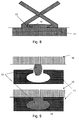
- Fig. 9 shows even an alternative coupling, where one or more catches (13) as the inflatable sections (6) is an inflatable balloon or bladder shape to be inserted into notches.
- the pressure of the media ensures the catch(es) (13) fills the notches (16) forming a stable coupling.
- This embodiment is especially relevant due to the system in relation to the aid tool (1) already may include means to inflate such a balloon or bladder like catch (13).
- the holding and release mechanism then is related to the pressure, to maintain or release the pressure and media within the catch (13).
- the catch (13) preferably would be filled at some lesser pressure during coupling.
- a magnetic spring clutch as for example found in air conditioning compressors is introduced with a set of coils wound in a circular fashion.
- the system then further comprises a flat surface having the same purpose as a flywheel.
- This whole unit rotates around for example the compressor driven by a belt.
- a driveshaft protrudes through the centre of the flat surface and attached hereto is a round disc.
- This disc acts like a clutch in a car.
- This clutch disc is in very close proximity to the flat bearing surface and held away by the use of metallic springs on the forward side of the clutch disc.
- When power is applied to the compressor clutch it causes an electromagnetic field in the coils behind the clutch disc.
- This magnetic field attracts the clutch disc to the flat surface of the bearing like a magnet picking up a nail.
- the magnetic force overcomes the resistance of the springs, and the clutch locks up solid to the flat surface of the bearing and turns the compressor.
- Fig. 10 illustrates a further important aspect of the present system utilizing the introduction of easy coupling of the tool (1) to and from mounting means (7) by first (10) and second (11) coupling elements.
- any imaginable tool (22) may easily be attached to the mounting means (22), such as, but not limited to, a knife as illustrated. The user would therefore not need to hold the tool by the hand, but only handle the tool by using the arm and / or other body parts.
- Fig. 11 illustrates an example of the same device where the mounting means (7) does not fully encircle the arm as such, but rather spirals on the body part. This is especially suited for systems where the tool (1, 22) is permanently coupled to the mounting means (7), these thus being one single device to be exchanged when a new tool (1, 22) is required.
- Fig. 12 shows an alternative example where the first coupling means (10) includes straps (23) to be tied around a part of the tool (22), being the second coupling means (11) itself.
- the straps (23) then may be tightened in any known manner, such as by introducing buckles, the straps (23) then operating as belts, or by introducing tightening means, either a mechanical or electrical tool, to tighten the straps (23) around the tool, such as by wrapping it at a spindle in the mounting means (7), either mechanically or electrically by a small motor.
- the straps (23) may alternatively be some material changing the length due to an electrical stimulus etc., for example an electrostrictive polymer, electroactive polymer or some familiar technology.
- the tightening means then may include means to register when the tightening has reached some predetermined resistance, for example measured by a motor torque, current or voltage, numbers of turns or any other manner indicating that the tool (22) is tightened enough to the mounting means (7).
- Different strategies may be introduced in relation to the mounting of the mounting means (7). Either the mounting means (7) and the tool forms one single device to be exchanged according to need, or the mounting means (7) are more or less permanently fixed to a body part, the tools (1, 22) being exchanged according to need, using first (10) and second (11) couplers.
- the mounting means (7) may be such they are to be attached to the body part by the user, perhaps to be detached when not needed for example during sleep, or by for example specialists to be attached to the body part more permanently.
- the mounting means (7) may be attached to the body part in a base station, for example to ensure the mounting means (7) to be fixed firmly and comfortable to the body part for secure handling of the tools. In the same manner the mounting means (7) may have to be detached in a base station.
- the base station may be such that it is being operated by specialists for example at a hospital, or may be at the home of the person, where the person is able to operate the base station by themselves.
- Fig. 13A illustrates a preferred set up of the aid tool (1) according to the present invention where one of three grippers (2) are associated with the thumb, this being positioned parallel to the two other grippers (2) in a symmetric manner. This ensures a good and symmetric grip in many circumstances.
- At least one of the grippers (2) is able to change position, such as by a parallel shift to be positioned directly opposite to another gripper (2), as also illustrated in Fig. 13B .
- At least one of the grippers (2) is able to move with the associated finger (preferable the thumb) such that it may rotate at it fixing point to the main body (100) of the aid tool (1) at least to a degree where it can extend with at least a part of it being directly opposite to another of the grippers (2), with at least one gripper being positioned with an angle different from 0 degrees relative to this opposite gripper (2), as also illustrated in Fig. 13C .
- the mounting means (7) may be equipped with inflatable bags internally in a manner, where, when the bags are filled with some media at some pressure, then the bags squeezes to the body part whereto the mounting means (7) are to be fixed. The more media filled into the bags, the more tightly the mounting means (7) will be fixed to the body part.
- Fig. 14 illustrates one non-limiting embodiment of the aid tool (1) according to the present invention.
- the figure shows the aid tool (1) with the grippers (2) being coupled (8) to the mounting means (7), and where the coupling (8) comprises two flexible joints (101) where they respectively gives an up-and-down and a side-to-side movement, or rotation, of the aid tool (1) in relation to the mounting means (7).
- These flexible joints (101) however are adapted to lock in their rotation when the aid tool (1) is activated, thus 'freezing' the relative positions at least substantially into their relative positions at the time of activation.
- At least one of the grippers (2) is driven by the wire (102) pulling the grippers (2), and where the wire (102) is connected to a rack (103), where the rack (103) again is being operated by a pinion-system (104) in a manner where the teeth of the rack and connected pinion is shaped such that the connected pinion may prevent the rack from movement in the direction to loosen the grip of the grippers (2) when the system as activated, but does not prevent it to move in the direction to fasten the grip (this being another example of the principle of unidirectional tightening explained earlier).
- a craftsman will recognise how to make the teeth of rack (103) and pinion (104) to achieve this, or any other manner where a similar effect may be achieved for example by having the pinion (104) locking in rotation in one but not the opposite direction, by motor control, by actuator control etc.
- the illustrated embodiment comprises an electric motor (105) to drive e.g. the pinion system (104).
- the present invention is not limited to the exact manner this is achieved, but to the important aspect, that even though the grippers (2) have been locked by activation of the system, this is only to be understood as locking in the loosening direction, not in the tightening direction of the grippers (2).
- the persons using the aid tools (1) may themselves fasten the grip by tightening the grippers (2) with their own fingers, the system preventing the grip to be loosened again even though the person loosen the grip of the fingers, at least until the system is deactivated again.
- the system operates such that after activation the grip of the grippers (2) will be tightened slightly more than it was at the time of activation, in order to tighten the grip slightly more. How much the grippers (2) further will tighten the grip may depend on several factors, like being predefined, depending on some activation of the user of the aid tool (2) optionally operated by the second hand and / or depending on a strain gauge of one or more of the grippers (2) adapted to measure the tightening force, where e.g. one or more of these may be used by and algorithm to calculate the further tightening grip.
- the locking mechanism of the flexible joints (101) is also driven by wires as (102) and may in one embodiment comprise a latch (106) driven by the wires, where the latch comprises a number of 'freezing' positions according to the actual position of the aid tool (1) to the mounting means (7) when activated.
- This may constitute a pin being pushed into the nearest of a number of teeth of a rack-like structure (107) as illustrated in Fig. 15 , where the rack-like structure (107) are attached to one 'side' of the joint (101) and the pin to the other 'side', thus when activated the pin locks into the nearest position of the rack like structure at activation, thus freezing it into this position.
- any other systems as they will be well known to a craftsman will also apply to the present invention.
- Fig. 16 illustrates a further example that might be incorporated into the system.
- the grippers (2) may comprise rotation contact sections (108) being squeezed to press on the object (4) with a force depending on the rotation, such as the illustrated example, where the rotation contact sections (108) by friction in the contact to a object (4), are moved against a spring element (109) adapted to squeeze the rotation contact sections (108) against the object (4).
- Such systems are well established e.g. for oil filters, and any embodiment as it will be known by a craftsman will apply to the present invention.
- the operation of the aid tool (1) according to the main embodiment is:
Landscapes
- Health & Medical Sciences (AREA)
- Animal Behavior & Ethology (AREA)
- Public Health (AREA)
- Engineering & Computer Science (AREA)
- Biomedical Technology (AREA)
- Heart & Thoracic Surgery (AREA)
- Vascular Medicine (AREA)
- Veterinary Medicine (AREA)
- Life Sciences & Earth Sciences (AREA)
- General Health & Medical Sciences (AREA)
- Transplantation (AREA)
- Orthopedic Medicine & Surgery (AREA)
- Cardiology (AREA)
- Oral & Maxillofacial Surgery (AREA)
- Nursing (AREA)
- Prostheses (AREA)
- Manipulator (AREA)
Claims (12)
- Hilfswerkzeug (1) mit wenigstens zwei Greifern (2) und Mitteln, um jeden Greifer (2) mit einem Finger einer Person zu befestigen, wobei die Greifer (2) angepasst sind, um den Fingern wenigstens in die Richtungen zu folgen, um einen Gegenstand (4) zu ergreifen und ihn freizugeben,
dadurch gekennzeichnet, dass
das Hilfswerkzeug (1) des Weiteren einen Aktivierungsschalter (5) umfasst, wobei das Hilfswerkzeug (1) durch Betätigen des Betätigungsschalters (5) mit einer vorgegebenen Kraft aktiviert wird, wobei eine Aktivierung des Hilfswerkzeugs (1) die Greifer (2) unidirektional verriegelt, so dass sie in ihrer Bewegung in der Löserichtung verriegelt sind. - Hilfswerkzeug (1) nach Anspruch 1, wobei die Greifer angeordnet sind, um einen Halt am Gegenstand (4) durch Ausbilden einer zusätzlichen Haltekraft am Gegenstand (4) aufzubauen, wobei die zusätzliche Haltekraft größer ist als die Haltekraft zum Zeitpunkt der Aktivierung.
- Hilfswerkzeug (1) nach Anspruch 2, wobei der Halt durch die Greifer (2) hergestellt wird, um sich nach der Aktivierung in die Greifrichtung zu bewegen, um einen etwas festeren Griff als zum Zeitpunkt der Aktivierung auszubilden.
- Hilfswerkzeug (1) nach Anspruch 3, wobei die Greifer (2) elastisch verformbare Kontaktabschnitte (6) umfassen.
- Hilfswerkzeug (1) nach einem der vorhergehenden Ansprüche, wobei der Aktivierungsschalter (2) auf einem Greifer (2) positioniert ist und angepasst ist, um durch den Finger, an dem der Greifer (2) angebracht ist, aktiviert zu werden.
- Hilfswerkzeug (1) nach Anspruch 5, wobei die Greifer (2) zwischen den Fingern und dem Gegenstand (4) zu positionieren sind.
- Hilfswerkzeug (1) nach einem beliebigen der vorhergehenden Ansprüche, wobei die Greifer (2) an Befestigungsmittel (7) gekoppelt (8) sind und wobei die Kopplung (8) zwei biegsame Gelenke (101) umfasst, die jeweils eine Auf-und-ab- und eine Seite-zu-Seite-Bewegung oder -Drehung der Greifer (2) in Bezug auf die Befestigungseinrichtung (7) ermöglichen.
- Hilfswerkzeug (1) nach Anspruch 7, wobei die biegsamen Gelenke (101) jedoch ausgelegt sind, sich in ihrer Drehung zu verriegeln, wenn das Hilfswerkzeug (1) aktiviert ist, wodurch die relativen Positionen wenigstens im Wesentlichen in ihren relativen Positionen zum Zeitpunkt der Aktivierung "einfrieren".
- Hilfswerkzeug (1) nach einem beliebigen der Ansprüche 1-6, wobei das Hilfswerkzeug (1) des Weiteren umfasst:- Befestigungsmittel (7), die ausgelegt sind, um an einem Körperteil befestigt zu werden;- erste Kopplungsmittel (10) mit einer vorgespannten Sperrklinke (13) mit einer ersten Position und mit einer zweiten Position;- einen Haltemechanismus (15), welcher angepasst ist, um die Sperrklinke (13) in der zweiten Position zu halten;- Freigabemittel (12), welche ausgelegt sind, die Klinke (13) aus dem Haltemechanismus (15) zu lösen,wobei das Werkzeug (1) ein zweites Koppelungsmittel (11) umfasst und wobei entweder das erste Kopplungsmittel (10) oder das zweite Kopplungsmittel (11) einen Antriebsmechanismus (17) umfasst, welcher ausgelegt ist, um die vorgespannte Sperrklinke (13) von einer ersten in eine zweite Position zu bewegen.
- Hilfswerkzeug (1) nach einem beliebigen der vorhergehenden Ansprüche, wobei das Hilfswerkzeug (1) Mittel zur Energiespeicherung umfasst.
- Hilfswerkzeug (1) nach Anspruch 10, wobei das Energiemittel während des Koppelns, Entkoppelns und/oder Handhabens des Werkzeuges (1) aufgeladen wird.
- Verfahren zur Betätigung eines Hilfswerkzeugs (1), wie in einem beliebigen der Ansprüche 1-11 beansprucht, um in Verbindung mit den Fingern einer Person verwendet zu werden, wobei das Hilfswerkzeug (1) wenigstens zwei Greifer (2) aufweist, wobei das Verfahren die Schritte umfasst, dass:- eine Person, die das Hilfswerkzeug (1) verwendet, das Hilfswerkzeug (1) positioniert, um einen lockeren Griff auf einem Gegenstand (4) mit den Greifern (2) auszubilden,- wenn das Hilfswerkzeug (1) in der Position ist, die Person einen Aktivierungsschalter (5) aktiviert, wodurch die Greifer (2) unidirektional in ihrer gegenwärtigen Position verriegelt werden, wobei die Greifer (2) dadurch in ihrer Bewegung in einer Löserichtung verriegelt sind, aber sein frei können, sich in einer Greifrichtung zu bewegen und- einen Halt auf dem Gegenstand (4) durch Festigen des Griffs auf den Gegenstand (4) durch Erhöhen der Festigkeit des Griffs relativ zur Stärke des Griffs zum Zeitpunkt der Aktivierung aufzubauen.
Priority Applications (1)
| Application Number | Priority Date | Filing Date | Title |
|---|---|---|---|
| EP16165996.6A EP3097890A3 (de) | 2010-05-06 | 2011-05-06 | Griffunterstützungsvorrichtung mit einem werkzeug und einer befestigung für das werkzeug |
Applications Claiming Priority (2)
| Application Number | Priority Date | Filing Date | Title |
|---|---|---|---|
| DKPA201000398 | 2010-05-06 | ||
| PCT/DK2011/000044 WO2011137904A1 (en) | 2010-05-06 | 2011-05-06 | Grasping aid device including a tool and an attaching of the tool |
Related Child Applications (2)
| Application Number | Title | Priority Date | Filing Date |
|---|---|---|---|
| EP16165996.6A Division EP3097890A3 (de) | 2010-05-06 | 2011-05-06 | Griffunterstützungsvorrichtung mit einem werkzeug und einer befestigung für das werkzeug |
| EP16165996.6A Division-Into EP3097890A3 (de) | 2010-05-06 | 2011-05-06 | Griffunterstützungsvorrichtung mit einem werkzeug und einer befestigung für das werkzeug |
Publications (2)
| Publication Number | Publication Date |
|---|---|
| EP2525748A1 EP2525748A1 (de) | 2012-11-28 |
| EP2525748B1 true EP2525748B1 (de) | 2016-06-22 |
Family
ID=44305757
Family Applications (2)
| Application Number | Title | Priority Date | Filing Date |
|---|---|---|---|
| EP16165996.6A Withdrawn EP3097890A3 (de) | 2010-05-06 | 2011-05-06 | Griffunterstützungsvorrichtung mit einem werkzeug und einer befestigung für das werkzeug |
| EP11721225.8A Not-in-force EP2525748B1 (de) | 2010-05-06 | 2011-05-06 | Einrichtung zur unterstützung der greiffunktion mit einer vorrichtung sowie einer befestigung der vorrichtung |
Family Applications Before (1)
| Application Number | Title | Priority Date | Filing Date |
|---|---|---|---|
| EP16165996.6A Withdrawn EP3097890A3 (de) | 2010-05-06 | 2011-05-06 | Griffunterstützungsvorrichtung mit einem werkzeug und einer befestigung für das werkzeug |
Country Status (5)
| Country | Link |
|---|---|
| US (2) | US9084690B2 (de) |
| EP (2) | EP3097890A3 (de) |
| CN (1) | CN102883689B (de) |
| DK (1) | DK2525748T3 (de) |
| WO (1) | WO2011137904A1 (de) |
Families Citing this family (16)
| Publication number | Priority date | Publication date | Assignee | Title |
|---|---|---|---|---|
| US9144529B2 (en) * | 2011-07-27 | 2015-09-29 | Stephen Lynn Culver | Range of motion assistant |
| DK177559B1 (en) * | 2012-11-29 | 2013-10-14 | Invencon Aps | Aid grabbing tool with force activated gripping function |
| DK177548B1 (en) * | 2012-11-29 | 2013-10-07 | Invencon Aps | Aid grabbing tool with hand operated gripper that can be pushed aside |
| WO2015120083A1 (en) | 2014-02-04 | 2015-08-13 | Rehabilitation Institute Of Chicago | Modular and lightweight myoelectric prosthesis components and related methods |
| US10817056B2 (en) | 2014-07-21 | 2020-10-27 | Shenzhen Dexta Robotics Co. Ltd. | Hand exoskeleton force feedback system |
| US10423227B2 (en) * | 2014-07-21 | 2019-09-24 | Dexta Robotics | Hand exoskeleton force feedback system |
| US20160367383A1 (en) * | 2015-06-19 | 2016-12-22 | Rehabilitation Institute Of Chicago | Lockable Finger System and Related Methods |
| WO2018218129A1 (en) | 2017-05-25 | 2018-11-29 | Vanderbilt University | Upper extremity assistance device |
| WO2019000109A1 (es) * | 2017-06-30 | 2019-01-03 | Lopez Anwandter Stephie Barbara Graciela | Kit ortésico para personas con extremidades superiores amputadas o atrofiadas |
| US20210068988A1 (en) * | 2017-11-12 | 2021-03-11 | Sze Kit Ho | Driving Assembly for Moving Body Part |
| CN108045926B (zh) * | 2017-11-16 | 2020-02-07 | 湖北宇瑞建筑工程有限公司 | 一种建筑用防护手掌的抓砖装置 |
| CN108001932B (zh) * | 2017-12-21 | 2019-12-20 | 江苏九城建筑安装工程有限公司 | 一种建筑木工用防木刺抓套 |
| GB2574596A (en) * | 2018-06-08 | 2019-12-18 | Epic Inventing Inc | Prosthetic device |
| DE202020004278U1 (de) | 2020-10-09 | 2020-12-01 | Ralf Athmann | Mechanisch mit einer Hand zu öffnender Griff für eine zylinderförmige Oberfläche, damit die Haut der Hand keinen direkten Kontakt zur zylinderförmigen Oberfläche herstellt. |
| USD980990S1 (en) * | 2021-11-05 | 2023-03-14 | Shenzhen Kunshengze Electronic Commerce Co., Ltd. | Finger stretcher |
| US20260020532A1 (en) * | 2024-07-19 | 2026-01-22 | Kevin Alvarez | Finger-mounted garden trimmer assembly |
Family Cites Families (42)
| Publication number | Priority date | Publication date | Assignee | Title |
|---|---|---|---|---|
| US1388618A (en) * | 1920-06-17 | 1921-08-23 | Stein Alec | Finger-protector |
| US1990553A (en) * | 1933-11-21 | 1935-02-12 | Koffler Max | Mitt |
| US2858947A (en) * | 1953-11-16 | 1958-11-04 | Garrett Corp | Remote control manipulating apparatus |
| DE2109753C3 (de) * | 1971-03-02 | 1973-09-13 | Otto Bock Orthopaedische Industrie Kg, 3428 Duderstadt | Zusatzgerat fur Handprothesen |
| US3781052A (en) * | 1972-04-03 | 1973-12-25 | Hims Inc | Safety apparatus |
| US3862507A (en) * | 1973-12-10 | 1975-01-28 | Emerson F Martyn | Fish bait holder |
| US3967321A (en) * | 1975-02-05 | 1976-07-06 | Indiana University Foundation | Electrically driven hand orthosis device for providing finger prehension |
| DE2615209A1 (de) | 1975-04-15 | 1976-10-28 | Teufel Wilh Jul Fa | Universal-orthese |
| US4035865A (en) * | 1976-01-19 | 1977-07-19 | Mcrae Lucy Theresa | Implements usable by persons afflicted with arthritis |
| US4149532A (en) | 1976-12-27 | 1979-04-17 | Terry Thomas E | Cerebral palsy arm and hand brace |
| US4167044A (en) * | 1978-02-23 | 1979-09-11 | Iowa State University Research Foundation, Inc. | Means for actuating artificial or disabled arm members |
| US4252360A (en) * | 1979-06-12 | 1981-02-24 | Gallaher Jr John K | Mechanical handling apparatus |
| US4523781A (en) * | 1984-02-23 | 1985-06-18 | Hal Brody | Gripping aid for the manually disabled |
| US4884581A (en) * | 1986-08-07 | 1989-12-05 | Josephine Rescigno | Oral hygiene tongue holder |
| US4711482A (en) * | 1987-02-24 | 1987-12-08 | N/C Industries | Reaching aid for the handicapped |
| US4846518A (en) * | 1987-09-11 | 1989-07-11 | Pleasant Company | Gripping device for a doll's extremity |
| US5002561A (en) * | 1989-08-17 | 1991-03-26 | Fisher Frank E | Protective hand forceps |
| US5413611A (en) * | 1992-07-21 | 1995-05-09 | Mcp Services, Inc. | Computerized electronic prosthesis apparatus and method |
| DE4325655A1 (de) * | 1993-07-30 | 1995-02-02 | Kai Henning Spandau | Selbsttätig sperrendes Gelenk, insbesondere Orthesengelenk |
| DE4416509C1 (de) | 1994-05-10 | 1995-11-23 | Bock Orthopaed Ind | Verfahren zur myoelektrischen Steuerung eines Kunstgliedes |
| US5853210A (en) * | 1996-05-02 | 1998-12-29 | Robinson; Gale | Pen and instrument holder for physically impaired hands |
| US5800561A (en) | 1996-05-15 | 1998-09-01 | Massachusetts Institute Of Technology | Power-assisted upper extremity orthosis |
| US5770297A (en) * | 1996-10-01 | 1998-06-23 | Grubich; Ivan J. | Gripping device |
| US6059694A (en) * | 1998-06-15 | 2000-05-09 | Villepigue; James | Hand exerciser employing finger power bands |
| SE9803257D0 (sv) * | 1998-09-25 | 1998-09-25 | Camp Scandinavia Ab | Knäortos med sagittal justering |
| US6594552B1 (en) * | 1999-04-07 | 2003-07-15 | Intuitive Surgical, Inc. | Grip strength with tactile feedback for robotic surgery |
| JP4014792B2 (ja) * | 2000-09-29 | 2007-11-28 | 株式会社東芝 | マニピュレータ |
| US20030218344A1 (en) * | 2002-04-22 | 2003-11-27 | Garrett John Olin | Ultimate grip |
| US20030221356A1 (en) * | 2002-05-28 | 2003-12-04 | Thomas Trozera | Locking tweezers for securing beads or weights used in tying fishing flies |
| US6739220B1 (en) | 2002-08-12 | 2004-05-25 | Wagic, Inc. | Motorized light bulb changer |
| NL1021653C2 (nl) | 2002-10-15 | 2004-05-11 | Robert Leonard Krullaards | Trainingsinrichting. |
| US6874833B2 (en) * | 2003-01-10 | 2005-04-05 | Glen S. Keith | Pickup tool with variable position limiting and variable axis of operation |
| US6866314B2 (en) * | 2003-01-24 | 2005-03-15 | Yong Hoon Cho | Padded tweezers |
| CN1981720A (zh) * | 2005-12-16 | 2007-06-20 | 上海科生假肢有限公司 | 曲线自锁式索牵引手头 |
| SE530293C2 (sv) * | 2006-09-01 | 2008-04-22 | Hans Von Holst | Kraftförstärkande handske |
| US8926534B2 (en) * | 2006-09-19 | 2015-01-06 | Myomo, Inc. | Powered orthotic device and method of using same |
| US9174344B2 (en) * | 2006-12-19 | 2015-11-03 | Deakin University | Method and apparatus for haptic control |
| US8419092B2 (en) * | 2007-08-10 | 2013-04-16 | Eric Zimmermann | Food handling device |
| US8919838B2 (en) * | 2007-08-10 | 2014-12-30 | Poi Domani Marketing Products, LLC | Food handling device |
| FR2928832B1 (fr) * | 2008-03-21 | 2012-01-13 | Gibaud | Orthese de poignet, destinee au traitement du syndrome du canal carpien |
| CN201299671Y (zh) * | 2008-07-14 | 2009-09-02 | 阙玉涛 | 佩戴式机械仿真手指 |
| US8622939B2 (en) | 2010-09-03 | 2014-01-07 | Bes Rehab Ltd. | Apparatus for manipulating joints of a limb |
-
2011
- 2011-05-06 CN CN201180022761.1A patent/CN102883689B/zh not_active Expired - Fee Related
- 2011-05-06 US US13/520,608 patent/US9084690B2/en not_active Expired - Fee Related
- 2011-05-06 DK DK11721225.8T patent/DK2525748T3/en active
- 2011-05-06 EP EP16165996.6A patent/EP3097890A3/de not_active Withdrawn
- 2011-05-06 WO PCT/DK2011/000044 patent/WO2011137904A1/en not_active Ceased
- 2011-05-06 EP EP11721225.8A patent/EP2525748B1/de not_active Not-in-force
-
2015
- 2015-06-15 US US14/739,521 patent/US20150342758A1/en not_active Abandoned
Non-Patent Citations (1)
| Title |
|---|
| None * |
Also Published As
| Publication number | Publication date |
|---|---|
| DK2525748T3 (en) | 2016-09-19 |
| EP2525748A1 (de) | 2012-11-28 |
| US9084690B2 (en) | 2015-07-21 |
| US20150342758A1 (en) | 2015-12-03 |
| US20130035771A1 (en) | 2013-02-07 |
| EP3097890A3 (de) | 2016-12-07 |
| CN102883689B (zh) | 2015-06-03 |
| EP3097890A2 (de) | 2016-11-30 |
| WO2011137904A1 (en) | 2011-11-10 |
| CN102883689A (zh) | 2013-01-16 |
Similar Documents
| Publication | Publication Date | Title |
|---|---|---|
| EP2525748B1 (de) | Einrichtung zur unterstützung der greiffunktion mit einer vorrichtung sowie einer befestigung der vorrichtung | |
| In et al. | Exo-glove: A wearable robot for the hand with a soft tendon routing system | |
| CN108621129B (zh) | 柔性驱动式机械手 | |
| EP3414061B1 (de) | Vorrichtung zur verbesserung der greiffähigkeit eines benutzers | |
| EP3706702B1 (de) | Handexoskelettvorrichtung | |
| US9931229B2 (en) | Gripping device with switchable prehension modes | |
| JP2020505981A (ja) | 流体駆動アクチュエータとその応用 | |
| JP6734927B2 (ja) | 動作支援装置 | |
| EP2737880B1 (de) | Hilfsgreiferwerkzeug für mit Kraft aktivierte Greiffunktion | |
| EP2737879B1 (de) | Hilfsgreiferwerkzeug für handbetätigten Greifer, der zur Seite geschoben werden kann | |
| WO2018218129A1 (en) | Upper extremity assistance device | |
| US20070276303A1 (en) | Gripping Device and Method | |
| Martinez et al. | A power-assisted exoskeleton optimized for pinching and grasping motions | |
| CN115957062A (zh) | 具有可交换的执行器组件的矫形器系统 | |
| US20160278946A1 (en) | Aid grabbing tool with hand operated gripper that can be pushed aside | |
| Miller-Jackson | A Soft Pneumatic Rotary Actuator Driven Hip Exoskeleton for Lower Limb Motion Assistance | |
| In | Soft Wearable Robotic Hand for People with Hand Paralysis |
Legal Events
| Date | Code | Title | Description |
|---|---|---|---|
| PUAI | Public reference made under article 153(3) epc to a published international application that has entered the european phase |
Free format text: ORIGINAL CODE: 0009012 |
|
| 17P | Request for examination filed |
Effective date: 20120821 |
|
| AK | Designated contracting states |
Kind code of ref document: A1 Designated state(s): AL AT BE BG CH CY CZ DE DK EE ES FI FR GB GR HR HU IE IS IT LI LT LU LV MC MK MT NL NO PL PT RO RS SE SI SK SM TR |
|
| DAX | Request for extension of the european patent (deleted) | ||
| 17Q | First examination report despatched |
Effective date: 20150414 |
|
| GRAP | Despatch of communication of intention to grant a patent |
Free format text: ORIGINAL CODE: EPIDOSNIGR1 |
|
| RAP1 | Party data changed (applicant data changed or rights of an application transferred) |
Owner name: MANUXA APS |
|
| INTG | Intention to grant announced |
Effective date: 20160215 |
|
| GRAS | Grant fee paid |
Free format text: ORIGINAL CODE: EPIDOSNIGR3 |
|
| GRAA | (expected) grant |
Free format text: ORIGINAL CODE: 0009210 |
|
| AK | Designated contracting states |
Kind code of ref document: B1 Designated state(s): AL AT BE BG CH CY CZ DE DK EE ES FI FR GB GR HR HU IE IS IT LI LT LU LV MC MK MT NL NO PL PT RO RS SE SI SK SM TR |
|
| REG | Reference to a national code |
Ref country code: GB Ref legal event code: FG4D |
|
| REG | Reference to a national code |
Ref country code: CH Ref legal event code: EP |
|
| REG | Reference to a national code |
Ref country code: IE Ref legal event code: FG4D |
|
| REG | Reference to a national code |
Ref country code: AT Ref legal event code: REF Ref document number: 807215 Country of ref document: AT Kind code of ref document: T Effective date: 20160715 |
|
| REG | Reference to a national code |
Ref country code: DE Ref legal event code: R096 Ref document number: 602011027554 Country of ref document: DE |
|
| REG | Reference to a national code |
Ref country code: CH Ref legal event code: NV Representative=s name: FIAMMENGHI-FIAMMENGHI, CH |
|
| REG | Reference to a national code |
Ref country code: DK Ref legal event code: T3 Effective date: 20160913 |
|
| REG | Reference to a national code |
Ref country code: NL Ref legal event code: FP |
|
| REG | Reference to a national code |
Ref country code: SE Ref legal event code: TRGR |
|
| REG | Reference to a national code |
Ref country code: LT Ref legal event code: MG4D |
|
| PG25 | Lapsed in a contracting state [announced via postgrant information from national office to epo] |
Ref country code: LT Free format text: LAPSE BECAUSE OF FAILURE TO SUBMIT A TRANSLATION OF THE DESCRIPTION OR TO PAY THE FEE WITHIN THE PRESCRIBED TIME-LIMIT Effective date: 20160622 Ref country code: NO Free format text: LAPSE BECAUSE OF FAILURE TO SUBMIT A TRANSLATION OF THE DESCRIPTION OR TO PAY THE FEE WITHIN THE PRESCRIBED TIME-LIMIT Effective date: 20160922 Ref country code: FI Free format text: LAPSE BECAUSE OF FAILURE TO SUBMIT A TRANSLATION OF THE DESCRIPTION OR TO PAY THE FEE WITHIN THE PRESCRIBED TIME-LIMIT Effective date: 20160622 |
|
| REG | Reference to a national code |
Ref country code: AT Ref legal event code: MK05 Ref document number: 807215 Country of ref document: AT Kind code of ref document: T Effective date: 20160622 |
|
| PG25 | Lapsed in a contracting state [announced via postgrant information from national office to epo] |
Ref country code: LV Free format text: LAPSE BECAUSE OF FAILURE TO SUBMIT A TRANSLATION OF THE DESCRIPTION OR TO PAY THE FEE WITHIN THE PRESCRIBED TIME-LIMIT Effective date: 20160622 Ref country code: RS Free format text: LAPSE BECAUSE OF FAILURE TO SUBMIT A TRANSLATION OF THE DESCRIPTION OR TO PAY THE FEE WITHIN THE PRESCRIBED TIME-LIMIT Effective date: 20160622 Ref country code: HR Free format text: LAPSE BECAUSE OF FAILURE TO SUBMIT A TRANSLATION OF THE DESCRIPTION OR TO PAY THE FEE WITHIN THE PRESCRIBED TIME-LIMIT Effective date: 20160622 Ref country code: GR Free format text: LAPSE BECAUSE OF FAILURE TO SUBMIT A TRANSLATION OF THE DESCRIPTION OR TO PAY THE FEE WITHIN THE PRESCRIBED TIME-LIMIT Effective date: 20160923 |
|
| PG25 | Lapsed in a contracting state [announced via postgrant information from national office to epo] |
Ref country code: RO Free format text: LAPSE BECAUSE OF FAILURE TO SUBMIT A TRANSLATION OF THE DESCRIPTION OR TO PAY THE FEE WITHIN THE PRESCRIBED TIME-LIMIT Effective date: 20160622 Ref country code: IS Free format text: LAPSE BECAUSE OF FAILURE TO SUBMIT A TRANSLATION OF THE DESCRIPTION OR TO PAY THE FEE WITHIN THE PRESCRIBED TIME-LIMIT Effective date: 20161022 Ref country code: CZ Free format text: LAPSE BECAUSE OF FAILURE TO SUBMIT A TRANSLATION OF THE DESCRIPTION OR TO PAY THE FEE WITHIN THE PRESCRIBED TIME-LIMIT Effective date: 20160622 Ref country code: IT Free format text: LAPSE BECAUSE OF FAILURE TO SUBMIT A TRANSLATION OF THE DESCRIPTION OR TO PAY THE FEE WITHIN THE PRESCRIBED TIME-LIMIT Effective date: 20160622 Ref country code: EE Free format text: LAPSE BECAUSE OF FAILURE TO SUBMIT A TRANSLATION OF THE DESCRIPTION OR TO PAY THE FEE WITHIN THE PRESCRIBED TIME-LIMIT Effective date: 20160622 Ref country code: SK Free format text: LAPSE BECAUSE OF FAILURE TO SUBMIT A TRANSLATION OF THE DESCRIPTION OR TO PAY THE FEE WITHIN THE PRESCRIBED TIME-LIMIT Effective date: 20160622 |
|
| PG25 | Lapsed in a contracting state [announced via postgrant information from national office to epo] |
Ref country code: PL Free format text: LAPSE BECAUSE OF FAILURE TO SUBMIT A TRANSLATION OF THE DESCRIPTION OR TO PAY THE FEE WITHIN THE PRESCRIBED TIME-LIMIT Effective date: 20160622 Ref country code: BE Free format text: LAPSE BECAUSE OF FAILURE TO SUBMIT A TRANSLATION OF THE DESCRIPTION OR TO PAY THE FEE WITHIN THE PRESCRIBED TIME-LIMIT Effective date: 20160622 Ref country code: AT Free format text: LAPSE BECAUSE OF FAILURE TO SUBMIT A TRANSLATION OF THE DESCRIPTION OR TO PAY THE FEE WITHIN THE PRESCRIBED TIME-LIMIT Effective date: 20160622 Ref country code: SM Free format text: LAPSE BECAUSE OF FAILURE TO SUBMIT A TRANSLATION OF THE DESCRIPTION OR TO PAY THE FEE WITHIN THE PRESCRIBED TIME-LIMIT Effective date: 20160622 Ref country code: PT Free format text: LAPSE BECAUSE OF FAILURE TO SUBMIT A TRANSLATION OF THE DESCRIPTION OR TO PAY THE FEE WITHIN THE PRESCRIBED TIME-LIMIT Effective date: 20161024 Ref country code: ES Free format text: LAPSE BECAUSE OF FAILURE TO SUBMIT A TRANSLATION OF THE DESCRIPTION OR TO PAY THE FEE WITHIN THE PRESCRIBED TIME-LIMIT Effective date: 20160622 |
|
| REG | Reference to a national code |
Ref country code: DE Ref legal event code: R097 Ref document number: 602011027554 Country of ref document: DE |
|
| REG | Reference to a national code |
Ref country code: FR Ref legal event code: PLFP Year of fee payment: 7 |
|
| PLBE | No opposition filed within time limit |
Free format text: ORIGINAL CODE: 0009261 |
|
| STAA | Information on the status of an ep patent application or granted ep patent |
Free format text: STATUS: NO OPPOSITION FILED WITHIN TIME LIMIT |
|
| 26N | No opposition filed |
Effective date: 20170323 |
|
| PG25 | Lapsed in a contracting state [announced via postgrant information from national office to epo] |
Ref country code: LU Free format text: LAPSE BECAUSE OF NON-PAYMENT OF DUE FEES Effective date: 20170531 Ref country code: SI Free format text: LAPSE BECAUSE OF FAILURE TO SUBMIT A TRANSLATION OF THE DESCRIPTION OR TO PAY THE FEE WITHIN THE PRESCRIBED TIME-LIMIT Effective date: 20160622 |
|
| PG25 | Lapsed in a contracting state [announced via postgrant information from national office to epo] |
Ref country code: MC Free format text: LAPSE BECAUSE OF FAILURE TO SUBMIT A TRANSLATION OF THE DESCRIPTION OR TO PAY THE FEE WITHIN THE PRESCRIBED TIME-LIMIT Effective date: 20160622 |
|
| REG | Reference to a national code |
Ref country code: IE Ref legal event code: MM4A |
|
| PG25 | Lapsed in a contracting state [announced via postgrant information from national office to epo] |
Ref country code: LU Free format text: LAPSE BECAUSE OF NON-PAYMENT OF DUE FEES Effective date: 20170506 |
|
| PG25 | Lapsed in a contracting state [announced via postgrant information from national office to epo] |
Ref country code: IE Free format text: LAPSE BECAUSE OF NON-PAYMENT OF DUE FEES Effective date: 20170506 |
|
| REG | Reference to a national code |
Ref country code: FR Ref legal event code: PLFP Year of fee payment: 8 |
|
| PGFP | Annual fee paid to national office [announced via postgrant information from national office to epo] |
Ref country code: DK Payment date: 20180514 Year of fee payment: 8 Ref country code: CH Payment date: 20180516 Year of fee payment: 8 |
|
| PGFP | Annual fee paid to national office [announced via postgrant information from national office to epo] |
Ref country code: NL Payment date: 20180523 Year of fee payment: 8 |
|
| PG25 | Lapsed in a contracting state [announced via postgrant information from national office to epo] |
Ref country code: MT Free format text: LAPSE BECAUSE OF NON-PAYMENT OF DUE FEES Effective date: 20170506 |
|
| PGFP | Annual fee paid to national office [announced via postgrant information from national office to epo] |
Ref country code: SE Payment date: 20180511 Year of fee payment: 8 |
|
| PG25 | Lapsed in a contracting state [announced via postgrant information from national office to epo] |
Ref country code: AL Free format text: LAPSE BECAUSE OF FAILURE TO SUBMIT A TRANSLATION OF THE DESCRIPTION OR TO PAY THE FEE WITHIN THE PRESCRIBED TIME-LIMIT Effective date: 20160622 |
|
| PG25 | Lapsed in a contracting state [announced via postgrant information from national office to epo] |
Ref country code: HU Free format text: LAPSE BECAUSE OF FAILURE TO SUBMIT A TRANSLATION OF THE DESCRIPTION OR TO PAY THE FEE WITHIN THE PRESCRIBED TIME-LIMIT; INVALID AB INITIO Effective date: 20110506 |
|
| PG25 | Lapsed in a contracting state [announced via postgrant information from national office to epo] |
Ref country code: BG Free format text: LAPSE BECAUSE OF FAILURE TO SUBMIT A TRANSLATION OF THE DESCRIPTION OR TO PAY THE FEE WITHIN THE PRESCRIBED TIME-LIMIT Effective date: 20160622 |
|
| PG25 | Lapsed in a contracting state [announced via postgrant information from national office to epo] |
Ref country code: CY Free format text: LAPSE BECAUSE OF NON-PAYMENT OF DUE FEES Effective date: 20160622 |
|
| PG25 | Lapsed in a contracting state [announced via postgrant information from national office to epo] |
Ref country code: MK Free format text: LAPSE BECAUSE OF FAILURE TO SUBMIT A TRANSLATION OF THE DESCRIPTION OR TO PAY THE FEE WITHIN THE PRESCRIBED TIME-LIMIT Effective date: 20160622 |
|
| REG | Reference to a national code |
Ref country code: CH Ref legal event code: PL |
|
| REG | Reference to a national code |
Ref country code: DK Ref legal event code: EBP Effective date: 20190531 |
|
| REG | Reference to a national code |
Ref country code: NL Ref legal event code: MM Effective date: 20190601 |
|
| PG25 | Lapsed in a contracting state [announced via postgrant information from national office to epo] |
Ref country code: SE Free format text: LAPSE BECAUSE OF NON-PAYMENT OF DUE FEES Effective date: 20190507 Ref country code: LI Free format text: LAPSE BECAUSE OF NON-PAYMENT OF DUE FEES Effective date: 20190531 Ref country code: CH Free format text: LAPSE BECAUSE OF NON-PAYMENT OF DUE FEES Effective date: 20190531 |
|
| PG25 | Lapsed in a contracting state [announced via postgrant information from national office to epo] |
Ref country code: TR Free format text: LAPSE BECAUSE OF FAILURE TO SUBMIT A TRANSLATION OF THE DESCRIPTION OR TO PAY THE FEE WITHIN THE PRESCRIBED TIME-LIMIT Effective date: 20160622 |
|
| PG25 | Lapsed in a contracting state [announced via postgrant information from national office to epo] |
Ref country code: DK Free format text: LAPSE BECAUSE OF NON-PAYMENT OF DUE FEES Effective date: 20190531 Ref country code: NL Free format text: LAPSE BECAUSE OF NON-PAYMENT OF DUE FEES Effective date: 20190601 |
|
| REG | Reference to a national code |
Ref country code: SE Ref legal event code: EUG |
|
| REG | Reference to a national code |
Ref country code: DE Ref legal event code: R082 Ref document number: 602011027554 Country of ref document: DE Representative=s name: KILBURN & STRODE LLP, NL |
|
| PGFP | Annual fee paid to national office [announced via postgrant information from national office to epo] |
Ref country code: GB Payment date: 20210414 Year of fee payment: 11 |
|
| PGFP | Annual fee paid to national office [announced via postgrant information from national office to epo] |
Ref country code: FR Payment date: 20220422 Year of fee payment: 12 Ref country code: DE Payment date: 20220406 Year of fee payment: 12 |
|
| GBPC | Gb: european patent ceased through non-payment of renewal fee |
Effective date: 20220506 |
|
| PG25 | Lapsed in a contracting state [announced via postgrant information from national office to epo] |
Ref country code: GB Free format text: LAPSE BECAUSE OF NON-PAYMENT OF DUE FEES Effective date: 20220506 |
|
| REG | Reference to a national code |
Ref country code: DE Ref legal event code: R119 Ref document number: 602011027554 Country of ref document: DE |
|
| PG25 | Lapsed in a contracting state [announced via postgrant information from national office to epo] |
Ref country code: DE Free format text: LAPSE BECAUSE OF NON-PAYMENT OF DUE FEES Effective date: 20231201 |
|
| PG25 | Lapsed in a contracting state [announced via postgrant information from national office to epo] |
Ref country code: FR Free format text: LAPSE BECAUSE OF NON-PAYMENT OF DUE FEES Effective date: 20230531 |