EP2526287B1 - Pale de rotor de turbine éolienne possédant un bord de fuite recourbé - Google Patents
Pale de rotor de turbine éolienne possédant un bord de fuite recourbé Download PDFInfo
- Publication number
- EP2526287B1 EP2526287B1 EP11701739.2A EP11701739A EP2526287B1 EP 2526287 B1 EP2526287 B1 EP 2526287B1 EP 11701739 A EP11701739 A EP 11701739A EP 2526287 B1 EP2526287 B1 EP 2526287B1
- Authority
- EP
- European Patent Office
- Prior art keywords
- trailing edge
- rotor blade
- wind turbine
- skin
- airfoil profile
- Prior art date
- Legal status (The legal status is an assumption and is not a legal conclusion. Google has not performed a legal analysis and makes no representation as to the accuracy of the status listed.)
- Active
Links
Images
Classifications
-
- F—MECHANICAL ENGINEERING; LIGHTING; HEATING; WEAPONS; BLASTING
- F03—MACHINES OR ENGINES FOR LIQUIDS; WIND, SPRING, OR WEIGHT MOTORS; PRODUCING MECHANICAL POWER OR A REACTIVE PROPULSIVE THRUST, NOT OTHERWISE PROVIDED FOR
- F03D—WIND MOTORS
- F03D1/00—Wind motors with rotation axis substantially parallel to the air flow entering the rotor
- F03D1/06—Rotors
- F03D1/065—Rotors characterised by their construction elements
- F03D1/0675—Rotors characterised by their construction elements of the blades
-
- F—MECHANICAL ENGINEERING; LIGHTING; HEATING; WEAPONS; BLASTING
- F05—INDEXING SCHEMES RELATING TO ENGINES OR PUMPS IN VARIOUS SUBCLASSES OF CLASSES F01-F04
- F05B—INDEXING SCHEME RELATING TO WIND, SPRING, WEIGHT, INERTIA OR LIKE MOTORS, TO MACHINES OR ENGINES FOR LIQUIDS COVERED BY SUBCLASSES F03B, F03D AND F03G
- F05B2240/00—Components
- F05B2240/20—Rotors
- F05B2240/30—Characteristics of rotor blades, i.e. of any element transforming dynamic fluid energy to or from rotational energy and being attached to a rotor
- F05B2240/31—Characteristics of rotor blades, i.e. of any element transforming dynamic fluid energy to or from rotational energy and being attached to a rotor of changeable form or shape
- F05B2240/311—Characteristics of rotor blades, i.e. of any element transforming dynamic fluid energy to or from rotational energy and being attached to a rotor of changeable form or shape flexible or elastic
-
- Y—GENERAL TAGGING OF NEW TECHNOLOGICAL DEVELOPMENTS; GENERAL TAGGING OF CROSS-SECTIONAL TECHNOLOGIES SPANNING OVER SEVERAL SECTIONS OF THE IPC; TECHNICAL SUBJECTS COVERED BY FORMER USPC CROSS-REFERENCE ART COLLECTIONS [XRACs] AND DIGESTS
- Y02—TECHNOLOGIES OR APPLICATIONS FOR MITIGATION OR ADAPTATION AGAINST CLIMATE CHANGE
- Y02E—REDUCTION OF GREENHOUSE GAS [GHG] EMISSIONS, RELATED TO ENERGY GENERATION, TRANSMISSION OR DISTRIBUTION
- Y02E10/00—Energy generation through renewable energy sources
- Y02E10/70—Wind energy
- Y02E10/72—Wind turbines with rotation axis in wind direction
Definitions
- the present invention relates to a wind turbine rotor blade.
- the present invention relates to a wind turbine rotor blade having a trailing edge that is configured to buckle benignly.
- Wind turbine rotor blades increase in size with the development of new wind turbines in order to increase the amount of energy that can be captured from the oncoming wind.
- the length of a rotor blade may be up to 60 meters and it is expected that the rotor blades will extend in length still further.
- the increasing lengths of rotor blades leads to an increase of structural loading on the rotor blade.
- a wind turbine rotor blade comprises a root section which connects to the hub of the wind turbine.
- the root section is typically circular in cross section for strength considerations.
- the root section blends into an aerodynamic profile along the spanwise length of the rotor blade.
- the rotor blades of a horizontal axis wind turbine rotate through a substantially vertical plane.
- the weight of the rotor blade itself generates alternating tensile and compression forces along its length as it rotates which results in cyclic loading of each rotor blade.
- the alternating tensile and compression forces are experienced along the leading edge of a blade and along the trailing edge of a blade.
- These loads are commonly referred to in the art as “edgewise loads", or they are sometimes known as “chordwise loads”.
- the edgewise loads are a result of gravitational loading and this edgewise loading increases from the tip of the blade to the root of the blade.
- Edgewise loads are experienced by both the leading and trailing edges. However, as the trailing edge is positioned further from the neutral axis of the rotor blade it experiences higher edgewise stresses than the leading edge.
- flapwise is typically used in the art to refer to the direction substantially normal to the chord of the blade, where the "chord” is the distance between the leading edge and the trailing edge; i.e. the flapwise direction is the direction in which the aerodynamic lift acts.
- the flapwise direction is perpendicular to the edgewise direction.
- a wind turbine rotor blade section comprising an airfoil profile between a leading edge and a trailing edge, the rotor blade section comprising:
- the portion of the trailing edge region is allowed to buckle benignly.
- the trailing edge In a baseline wind turbine rotor blade, the trailing edge is designed not to buckle. In the baseline rotor blade, the trailing edge is made sufficiently stiff so that it resists buckling. However, if the trailing edge of the baseline rotor blade is exposed to extreme loading, the trailing edge may buckle with catastrophic results.
- the trailing edge is designed to buckle in a benign manner so that a failure of the rotor blade is prevented. This is advantageous in that failure of the rotor blade is prevented, and the structural strength of the trailing edge may be reduced. By reducing the structural strength of the trailing edge means that less material is used in the manufacture of the trailing edge, thus saving on the bill of materials and self-weight loads for the rotor blade.
- reverse edgewise loading is meant the loads that are caused when the trailing edge of the rotor blade is subjected to a compressive load, and the leading edge of the rotor blade section is subjected to a tensile load.
- the portion of the trailing edge is configured to buckle when the rotor blade section is subjected to extreme reverse edgewise loading.
- the edgewise loading on the rotor blade is caused by gravity, aerodynamic loads and dynamic loads.
- the edgewise loading may become extreme as a result of wind gusts or turbulence for instance.
- extreme edgewise loading may mean edgewise loading that is typically 3 x gravity or greater.
- the extreme edgewise loading is a dynamic instantaneous extreme loading, for instance, the peak edgewise loading may exist for only 0.1 seconds. Such an extreme loading may occur only once in 50 years.
- the first structural member may be a spar which connects a windward and a leeward skin of the airfoil profile.
- the spar may be formed in a hollow box shape, with two spar caps and two shear webs as is well known in the art.
- the spar may be formed with a single shear web which extends between the windward skin and the leeward skin.
- the portion of the trailing edge region is configured to buckle in a flapwise direction.
- the trailing edge region will buckle so that it deforms out of plane, in that the trailing edge will assume a shape in the flapwise direction.
- At least part of the airfoil profile is formed from a windward skin and a leeward skin extending from the leading edge to the trailing edge; wherein; the windward skin and the leeward skin in the trailing edge region have a thickness that is less than the thickness of the windward skin and the leeward skin in a forward part of the airfoil profile.
- forward part of the airfoil profile is meant the part of the rotor blade section that is upwind of the trailing edge region and that is not designed to buckle.
- a thickness of the windward skin and the leeward skin in the trailing edge region is less than 50% of the thickness of the windward skin and the leeward skin in a forward part of the airfoil profile.
- the trailing edge region has a low spanwise stiffness compared to the baseline rotor blade so that it can buckle to relieve local edgewise stresses benignly.
- the thickness of the windward skin and the leeward skin in the trailing edge region may be between 5% and 50%, such as 10%, of the thickness of the windward skin and the leeward skin in a forward part of the airfoil profile.
- a second structural member supporting the airfoil profile disposed between the first structural member and the trailing edge is provided.
- the first structural member may be a main spar supporting the airfoil profile and the second structural member may be a rear spar located near the trailing edge region.
- a rear spar is sometimes necessary in a large blade (i.e. over 40 meters in length) to support the large chord of the rotor blade section.
- the airfoil profile between the leading edge and the second structural member has may have substantially zero camber.
- the "camber” is the asymmetry between the leeward and windward skins of the airfoil profile. When the camber is zero, the airfoil profile is symmetrical. By having zero camber in the forward part of the airfoil profile means that the forward part is more stable against buckling, or less buckling resisting material needs to be used in the forward part.
- the airfoil profile between the second structural member and the trailing edge may have camber.
- the camber is provided in the trailing edge region so that the airfoil profile will generate aerodynamic lift.
- the trailing edge region may be arranged to be fixed to the second structural member.
- the trailing edge region may be manufactured separately from the rest of the rotor blade section. Once the forward part of the rotor blade has been manufactured, the trailing edge region may be connected to the second structural member. This will save on manufacturing and transport costs.
- a wind turbine rotor blade comprising the wind turbine rotor blade section as described above, wherein:
- the first and second structural members are formed as a principal load being structure. When the trailing edge buckles in use, the loads in the trailing edge portion are transferred to the principal load bearing structure.
- the portion of the trailing edge may be configured to buckle in use, when the rotor blade is subjected to reverse edgewise loading, such that the transmittal of edgewise loads in the trailing edge portion is transferred away from the trailing edge portion to the first structural member and the second structural member.
- a wind turbine generator may comprise a rotor hub supported by a tower, and further comprising at least one rotor blade according as described above connected to the rotor hub.
- Such a wind turbine generator is a three bladed horizontal axis machine.
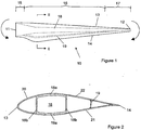
- Figures 1 and 2 show a plan view and a cross sectional view respectively of a wind turbine rotor blade 10.
- the blade 10 comprises a root end 11 for connection to a wind turbine hub (not shown) and a tip end 12.
- the blade 10 further comprises a leading edge 13 and a trailing edge 14.
- the region 15 is designated in this invention as the root end region of the rotor blade 10 and in this region, the cross-section of the blade is substantially circular.
- the region 16 may be referred to as the mid-blade region.
- a tip region is shown at 17.
- the root end region 15 may extend from the root end 11 to between 3% and 5% of the total span of the blade 10.
- the tip region 17 may extend from the tip end 12 to between 20% and 50% of the blade 10 span, from the tip end. Therefore, the mid span region 16 may extend from 3% to 5% from the blade root 11 to 50% to 80% from the blade root.
- the tip region 17 can be characterised as the spanwise part of the blade 10 that is not subjected
- the blade 10 comprises a first structural member 18 which is formed as a spar.
- the spar 18 comprises an upper and lower spar cap 18a and a leading and trailing shear web 18b to form a hollow box section which may extend from the root end 11 in the direction of the tip 12.
- the spar 18 is used to transfer load from the rotor blade 10 to the hub of the wind turbine. Such loads can be tensile and compression forces or torque.
- the spar 18 is formed from composite materials, in this example, glass and carbon reinforcing fibres set in a thermoset resin matrix.
- An aerodynamic shell 20 provides the aerodynamic profile and is supported by the spar 18.
- the shell comprises a windward skin 21 and a leeward skin 22, each of which extend from the leading edge 13 to the trailing edge 14.
- the shell may be formed from a composite material such as glass fibres embedded in a thermoset resin matrix.
- the spar 18 may form part of the external aerodynamic profile.
- a second structural member 19 is provided.
- the second structural member is a rear or trailing edge spar formed from carbon and glass fibre embedded in a thermoset resin matrix.
- the rear spar 19 acts as an additional stiffening mechanism in the trailing edge region of the blade 10.
- the rear spar 19 is integral with the spar 18 in the root end region 15 of the blade 10 and extends along the length of the blade towards the tip end 12.
- the rear spar 19 may form part of the external aerodynamic profile.
- the trailing edge 14 of the blade 10 is configured so that it undergoes a benign buckling under certain load conditions.
- the trailing edge is designed so that it buckles at extreme reverse edgewise loads.
- the construction of the blade 10 so that is designed to undergo a benign deflection is described further below.
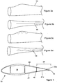
- Figures 3a to 3d show schematically how the trailing edge may buckle under extreme reverse edgewise loads.
- Figures 3a and 3b show a portion of a blade 10 subjected to no edgewise loading and it can be seen that the trailing edge 14 has not buckled.
- Figures 3c and 3d an extreme reverse edgewise load has been applied and it can be seen that the trailing edge 14 has buckled.
- the trailing edge 14 buckles in the mid-blade region 16 as defined above in Figure 1 .
- the trailing edge 14 undergoes buckling, this does not have a significant effect on the aerodynamic properties of the blade. Furthermore, as the main structural loads of the blade 10 are substantially carried through the spar 18 and the rear spar 19, the buckling of the trailing edge 14 does not have a negative effect on transmissions of loads along the length of the blade.
- the bucking of the trailing edge 14 results in the trailing edge "collapsing".
- the structural integrity of the trailing edge 14 is lost when the trailing edge buckles, but the loss of structural integrity is not a result of material failure.
- the buckling is an elastic deformation of the trailing edge 14 which results in a deflection of the trailing edge in the flapwise direction, i.e. the deflection is perpendicular to the edgewise load along the trailing edge 14.
- the trailing edge 14 does not experience plastic deformation. When the edgewise load that caused the trailing edge 14 to buckle is reduced, the trailing edge will spring back to its undeformed shape.
- Figure 4 illustrates an example of how the trailing edge 14 is designed to buckle.
- a trailing edge region 23 downwind of the rear spar 19 in the mid-blade region 16 is defined.
- the windward skin 21a and the leeward skin 22a are thin relative to the skin thickness in the rest of the airfoil profile.
- the windward skin 21a and the leeward skin 22a are formed from a single sheet of fibre glass reinforced polymer.
- the skins are formed from multiple sheets of fibre glass reinforced polymer.
- the skins 21a and 22a have a low bending stiffness compared to the bending stiffness of the rest of the airfoil profile.
- trailing edge region 23 in the mid-blade region 16 is only formed from a thin skin of composite, such as a single skin of composite, it has sufficient strength to maintain its shape due to the triangular nature of the trailing edge region 23, where the triangular shape is formed from the skins 21a and 22a and the rear spar 19.
- the chord of the rotor blade 10 is between 2 and 5 meters in the region where it designed to buckle.
- the thickness of the skins 21, 22 forward of the rear spar 19 is between 1% and 4% of the chordwise dimension, i.e. between 20mm and 80mm thick for a 2m chord.
- the thickness of the skins 21a, 22a in the trailing edge region 23 is between 0.1% and 0.4% of the chordwise dimension, i.e. between 2mm and 8mm for a 2m chord.
- the trailing edge region 23 When the trailing edge region 23 is subjected to the design loads for the wind turbine, the trailing edge region maintains its triangular shape and it forms part of the aerodynamic profile of the blade. However, when subjected to extreme reverse edgewise loads, the trailing edge region 23 will buckle. When the trailing edge region 23 has buckled, it will not transmit any significant part of the reverse edgewise loads.
- the trailing edge region 23 may also be designed to promote controlled and predicable buckling. Such designs may include gentle curves and a composite layup of thick and thin laminates to promote exactly where the trailing edge will buckle.
- the reverse edgewise loads are transmitted from the tip 12 of the blade towards the root 11 of the blade.
- the trailing edge 14 transmits 5% of the reverse edgewise loads and the spar 18, the rear spar 19 and the skins transmit the remaining 95% of the reverse edgewise loads.
- the trailing edge 14 buckles due to extreme reverse edgewise loading, the trailing edge will now no longer transmit any loads and the spar 18, the rear spar 19 and the skins outside the trailing edge region 23 will transmit substantially all of the reverse edgewise loading.
- the airfoil profile will change when the trailing edge 14 buckles.
- it is not critical to maintain an optimum aerodynamic profile because it only buckles for a short time (such as 0.1 seconds) and it will happen rarely (such as once in 50 years).
- the airfoil profile is unsymmetrical, i.e. it has camber.
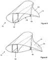
- Figure 5 shows how the trailing edge 14 may buckle with an unsymmetrical airfoil profile.
- the rear spar is supported unsymmetrical in that it is closer to the leeward side than the windward side.
- the trailing edge 14 is designed to buckle. If the reverse edgewise load is too high, it may cause the windward side to collapse inwards as shown by the arrow 24 which will cause the rear spar 19 to deflect towards the windward side.
- the airfoil profile is now symmetrical between the main spar 18 and the rear spar 19, that is there is zero camber, or substantially zero camber, between the main spar 18 and the rear spar 19.
- the trailing edge region downwind of the rear spar may also be symmetrical, or it may be unsymmetrical as shown in Figure 6 .
- all the camber is in the trailing edge region 23 of the blade 10.
- the likelihood of the rear spar 19 buckling is reduced because the load bearing structure is symmetrical and it is unlikely that the windward (or leeward) side will collapse inwards.
- the trailing edge region 23 will buckle as per its intended design.
- the trailing edge region 23 is designed so that it is manufactured separately from the rest of the rotor blade 10. This will result in simplified manufacture and simplified transport. The trailing edge region can then be assembled to the rest of the rotor blade 10 when the wind turbine is installed.
- the trailing edge region 23 may be connected to the rear spar 19 through mechanical fixings such as bolts or by adhesive.
Landscapes
- Engineering & Computer Science (AREA)
- Life Sciences & Earth Sciences (AREA)
- Sustainable Development (AREA)
- Sustainable Energy (AREA)
- Chemical & Material Sciences (AREA)
- Combustion & Propulsion (AREA)
- Mechanical Engineering (AREA)
- General Engineering & Computer Science (AREA)
- Wind Motors (AREA)
Claims (11)
- Section de pale de rotor d'éolienne comprenant un profil aérodynamique entre un bord d'attaque (13) et un bord de fuite (14), la section de pale de rotor comprenant :un premier élément structurel (18) supportant le profil aérodynamique ;le profil aérodynamique comprenant une région de bord de fuite (23) éloignée du premier élément structurel (18) dans une direction de corde ;caractérisée en ce que :une partie de la région de bord de fuite (23) du profil aérodynamique est configurée pour fléchir de façon bénigne et le bord de fuite ne subit pas de déformation plastique, en utilisation, lorsque la section de pale de rotor est soumise à une charge inverse extrême dans la direction longitudinale.
- Section de pale de rotor d'éolienne selon la revendication 1, dans laquelle la partie de la région de bord de fuite (23) est configurée pour fléchir dans une direction transversale.
- Section de pale de rotor d'éolienne selon la revendication 1 ou la revendication 2, dans laquelle au moins une partie du profil aérodynamique est formée à partir d'un revêtement face au vent (21) et d'un revêtement sous le vent (22) s'étendant du bord d'attaque (13) au bord de fuite (14) ; dans laquelle :le revêtement face au vent (21a) et le revêtement sous le vent (22a) dans la région de bord de fuite (23) ont une épaisseur qui est inférieure à l'épaisseur du revêtement face au vent et du revêtement sous le vent dans une partie avant du profil aérodynamique.
- Section de pale de rotor d'éolienne selon la revendication 3, dans laquelle une épaisseur du revêtement face au vent (21a) et du revêtement sous le vent (22a) dans la région de bord de fuite (23) est inférieure à 50 % de l'épaisseur du revêtement face au vent et du revêtement sous le vent dans une partie avant du profil aérodynamique.
- Section de pale de rotor d'éolienne selon l'une quelconque des revendications précédentes, comprenant en outre :un second élément structurel (19) supportant le profil aérodynamique disposé entre le premier élément structurel (18) et le bord de fuite (14).
- Section de pale de rotor d'éolienne selon l'une quelconque des revendications précédentes, dans laquelle le profil aérodynamique entre le bord d'attaque (13) et le second élément structurel (18) présente une cambrure sensiblement nulle.
- Section de pale de rotor d'éolienne selon la revendication 5 et la revendication 6, dans laquelle le profil aérodynamique entre le second élément structurel (19) et le bord de fuite (14) présente une cambrure.
- Section de pale de rotor d'éolienne selon la revendication 5, dans laquelle la région de bord de fuite (23) est agencée pour être fixée au second élément structurel (19).
- Pale de rotor d'éolienne (10) comprenant la section de pale de rotor d'éolienne selon l'une quelconque des revendications 5 à 8, dans laquelle :les premier (18) et second (19) éléments structuraux et le bord de fuite (14) sont configurés pour transmettre des charges inverses dans la direction longitudinale d'une extrémité de pointe (12) vers une extrémité d'emplanture (11) de la pale de rotor ; et dans laquellela partie du bord de fuite est configurée pour fléchir en utilisation, lorsque la pale de rotor est soumise à une charge inverse dans la direction longitudinale, de sorte que la transmission de charges dans la direction longitudinale dans la partie de bord de fuite soit transférée de la partie de bord de fuite au reste de la structure de pale d'éolienne.
- Pale de rotor d'éolienne (10) selon la revendication 9, dans laquelle la partie du bord de fuite est configurée pour fléchir en utilisation, lorsque la pale de rotor est soumise à une charge inverse dans la direction longitudinale, de sorte que la transmission de charges dans la direction longitudinale dans la partie bord de fuite soit transférée de la partie de bord de fuite au premier élément structurel et au second élément structurel.
- Eolienne comprenant un moyeu de rotor supporté par une tour, et comprenant en outre au moins une pale de rotor (10) selon la revendication 9 ou la revendication 10 reliée au moyeu de rotor.
Applications Claiming Priority (3)
| Application Number | Priority Date | Filing Date | Title |
|---|---|---|---|
| DKPA201070019 | 2010-01-21 | ||
| US29729010P | 2010-01-22 | 2010-01-22 | |
| PCT/DK2011/050015 WO2011088834A2 (fr) | 2010-01-21 | 2011-01-19 | Pale de rotor de turbine éolienne possédant un bord de fuite recourbé |
Publications (2)
| Publication Number | Publication Date |
|---|---|
| EP2526287A2 EP2526287A2 (fr) | 2012-11-28 |
| EP2526287B1 true EP2526287B1 (fr) | 2016-07-06 |
Family
ID=44307300
Family Applications (1)
| Application Number | Title | Priority Date | Filing Date |
|---|---|---|---|
| EP11701739.2A Active EP2526287B1 (fr) | 2010-01-21 | 2011-01-19 | Pale de rotor de turbine éolienne possédant un bord de fuite recourbé |
Country Status (3)
| Country | Link |
|---|---|
| EP (1) | EP2526287B1 (fr) |
| DK (1) | DK2526287T3 (fr) |
| WO (1) | WO2011088834A2 (fr) |
Families Citing this family (6)
| Publication number | Priority date | Publication date | Assignee | Title |
|---|---|---|---|---|
| GB201217212D0 (en) | 2012-09-26 | 2012-11-07 | Blade Dynamics Ltd | Windturbine blade |
| DK2908001T3 (da) | 2014-02-12 | 2017-01-02 | Siemens Ag | Midler til dæmpning af belastning på en vindmøllerotorvinge |
| EP3002452B1 (fr) | 2014-10-05 | 2019-07-24 | Pontis Group Holding B.V. | Pale d'eolienne |
| US10337490B2 (en) * | 2015-06-29 | 2019-07-02 | General Electric Company | Structural component for a modular rotor blade |
| CN113048007B (zh) * | 2019-12-26 | 2022-10-04 | 江苏金风科技有限公司 | 叶片、风力发电机组以及降低叶片呼吸效应的方法 |
| EP3904670A1 (fr) * | 2020-04-27 | 2021-11-03 | Siemens Gamesa Renewable Energy A/S | Pale de turbine éolienne |
Family Cites Families (3)
| Publication number | Priority date | Publication date | Assignee | Title |
|---|---|---|---|---|
| EP1613860B1 (fr) * | 2003-03-31 | 2015-11-04 | Technical University of Denmark | Regulation de puissance, de charges et/ou de stabilite d'une eolienne a axe horizontal au moyen d'une commande de geometrie d'aubes variable |
| FR2898865B1 (fr) * | 2006-03-27 | 2008-05-30 | Cetim Cermat Ass Loi De 1901 | Profil aerodynamique ou hydrodynamique pouvant etre deforme de maniere continue et controlee |
| WO2010000263A2 (fr) * | 2008-07-01 | 2010-01-07 | Danmarks Tekniske Universitet | Pale renforcée pour turbine éolienne |
-
2011
- 2011-01-19 EP EP11701739.2A patent/EP2526287B1/fr active Active
- 2011-01-19 DK DK11701739.2T patent/DK2526287T3/en active
- 2011-01-19 WO PCT/DK2011/050015 patent/WO2011088834A2/fr not_active Ceased
Also Published As
| Publication number | Publication date |
|---|---|
| DK2526287T3 (en) | 2016-08-29 |
| WO2011088834A2 (fr) | 2011-07-28 |
| EP2526287A2 (fr) | 2012-11-28 |
| WO2011088834A3 (fr) | 2011-12-29 |
Similar Documents
| Publication | Publication Date | Title |
|---|---|---|
| EP3303830B1 (fr) | Pale d'éolienne ayant une section d'espacement du bord de fuite | |
| DK178020B1 (da) | Spar cap-enhed til en vindmøllerotorvinge | |
| EP2318702B1 (fr) | Pale d'eolienne avec partie d'extension comportant un revêtement placé sur une ossature | |
| US10253751B2 (en) | Wind turbine blade assembled from inboard part and outboard part having different types of load carrying structures | |
| US9068559B2 (en) | Rotor blade for a wind turbine and a method for making the same | |
| EP2341238B1 (fr) | Pale de rotor d' éolienne | |
| EP2526287B1 (fr) | Pale de rotor de turbine éolienne possédant un bord de fuite recourbé | |
| EP2159414B1 (fr) | Pales d'éolienne avec treillis croisés | |
| AU2011226066B2 (en) | Wind turbine rotor blade | |
| EP2518314A1 (fr) | Pale rotative d'éolienne | |
| WO2013092852A1 (fr) | Pale d'éolienne assemblée à partir de parties de pale à l'intérieur et à l'extérieur | |
| US12503996B2 (en) | Wind turbine blade with leeward reinforcement structures and windward reinforcement structures | |
| US20240167450A1 (en) | A wind turbine blade | |
| EP4457433B1 (fr) | Pale d'éolienne et procédé de fabrication d'une pale d'éolienne | |
| CN121358946A (zh) | 风力涡轮机叶片 | |
| CA2986076C (fr) | Pale d'eolienne dotee d'une section d'espacement de bord de fuite | |
| CN120159689A (zh) | 一种抑制叶片变形的装置及抑制截面变形的叶片 | |
| EP2851557A1 (fr) | Pale d'eolienne avec des volets aérodynamiques placés au pied de la pale |
Legal Events
| Date | Code | Title | Description |
|---|---|---|---|
| PUAI | Public reference made under article 153(3) epc to a published international application that has entered the european phase |
Free format text: ORIGINAL CODE: 0009012 |
|
| 17P | Request for examination filed |
Effective date: 20120719 |
|
| AK | Designated contracting states |
Kind code of ref document: A2 Designated state(s): AL AT BE BG CH CY CZ DE DK EE ES FI FR GB GR HR HU IE IS IT LI LT LU LV MC MK MT NL NO PL PT RO RS SE SI SK SM TR |
|
| DAX | Request for extension of the european patent (deleted) | ||
| RAP1 | Party data changed (applicant data changed or rights of an application transferred) |
Owner name: VESTAS WIND SYSTEMS A/S |
|
| GRAP | Despatch of communication of intention to grant a patent |
Free format text: ORIGINAL CODE: EPIDOSNIGR1 |
|
| INTG | Intention to grant announced |
Effective date: 20151028 |
|
| INTG | Intention to grant announced |
Effective date: 20160121 |
|
| GRAS | Grant fee paid |
Free format text: ORIGINAL CODE: EPIDOSNIGR3 |
|
| GRAA | (expected) grant |
Free format text: ORIGINAL CODE: 0009210 |
|
| AK | Designated contracting states |
Kind code of ref document: B1 Designated state(s): AL AT BE BG CH CY CZ DE DK EE ES FI FR GB GR HR HU IE IS IT LI LT LU LV MC MK MT NL NO PL PT RO RS SE SI SK SM TR |
|
| REG | Reference to a national code |
Ref country code: GB Ref legal event code: FG4D |
|
| REG | Reference to a national code |
Ref country code: AT Ref legal event code: REF Ref document number: 810921 Country of ref document: AT Kind code of ref document: T Effective date: 20160715 Ref country code: CH Ref legal event code: EP |
|
| REG | Reference to a national code |
Ref country code: IE Ref legal event code: FG4D |
|
| REG | Reference to a national code |
Ref country code: DE Ref legal event code: R096 Ref document number: 602011027914 Country of ref document: DE |
|
| REG | Reference to a national code |
Ref country code: DK Ref legal event code: T3 Effective date: 20160822 |
|
| REG | Reference to a national code |
Ref country code: NL Ref legal event code: MP Effective date: 20160706 |
|
| REG | Reference to a national code |
Ref country code: LT Ref legal event code: MG4D |
|
| REG | Reference to a national code |
Ref country code: AT Ref legal event code: MK05 Ref document number: 810921 Country of ref document: AT Kind code of ref document: T Effective date: 20160706 |
|
| REG | Reference to a national code |
Ref country code: FR Ref legal event code: PLFP Year of fee payment: 7 |
|
| PG25 | Lapsed in a contracting state [announced via postgrant information from national office to epo] |
Ref country code: HR Free format text: LAPSE BECAUSE OF FAILURE TO SUBMIT A TRANSLATION OF THE DESCRIPTION OR TO PAY THE FEE WITHIN THE PRESCRIBED TIME-LIMIT Effective date: 20160706 Ref country code: IS Free format text: LAPSE BECAUSE OF FAILURE TO SUBMIT A TRANSLATION OF THE DESCRIPTION OR TO PAY THE FEE WITHIN THE PRESCRIBED TIME-LIMIT Effective date: 20161106 Ref country code: RS Free format text: LAPSE BECAUSE OF FAILURE TO SUBMIT A TRANSLATION OF THE DESCRIPTION OR TO PAY THE FEE WITHIN THE PRESCRIBED TIME-LIMIT Effective date: 20160706 Ref country code: LT Free format text: LAPSE BECAUSE OF FAILURE TO SUBMIT A TRANSLATION OF THE DESCRIPTION OR TO PAY THE FEE WITHIN THE PRESCRIBED TIME-LIMIT Effective date: 20160706 Ref country code: NL Free format text: LAPSE BECAUSE OF FAILURE TO SUBMIT A TRANSLATION OF THE DESCRIPTION OR TO PAY THE FEE WITHIN THE PRESCRIBED TIME-LIMIT Effective date: 20160706 Ref country code: NO Free format text: LAPSE BECAUSE OF FAILURE TO SUBMIT A TRANSLATION OF THE DESCRIPTION OR TO PAY THE FEE WITHIN THE PRESCRIBED TIME-LIMIT Effective date: 20161006 Ref country code: IT Free format text: LAPSE BECAUSE OF FAILURE TO SUBMIT A TRANSLATION OF THE DESCRIPTION OR TO PAY THE FEE WITHIN THE PRESCRIBED TIME-LIMIT Effective date: 20160706 Ref country code: FI Free format text: LAPSE BECAUSE OF FAILURE TO SUBMIT A TRANSLATION OF THE DESCRIPTION OR TO PAY THE FEE WITHIN THE PRESCRIBED TIME-LIMIT Effective date: 20160706 |
|
| PG25 | Lapsed in a contracting state [announced via postgrant information from national office to epo] |
Ref country code: AT Free format text: LAPSE BECAUSE OF FAILURE TO SUBMIT A TRANSLATION OF THE DESCRIPTION OR TO PAY THE FEE WITHIN THE PRESCRIBED TIME-LIMIT Effective date: 20160706 Ref country code: BE Free format text: LAPSE BECAUSE OF FAILURE TO SUBMIT A TRANSLATION OF THE DESCRIPTION OR TO PAY THE FEE WITHIN THE PRESCRIBED TIME-LIMIT Effective date: 20160706 Ref country code: PT Free format text: LAPSE BECAUSE OF FAILURE TO SUBMIT A TRANSLATION OF THE DESCRIPTION OR TO PAY THE FEE WITHIN THE PRESCRIBED TIME-LIMIT Effective date: 20161107 Ref country code: GR Free format text: LAPSE BECAUSE OF FAILURE TO SUBMIT A TRANSLATION OF THE DESCRIPTION OR TO PAY THE FEE WITHIN THE PRESCRIBED TIME-LIMIT Effective date: 20161007 Ref country code: ES Free format text: LAPSE BECAUSE OF FAILURE TO SUBMIT A TRANSLATION OF THE DESCRIPTION OR TO PAY THE FEE WITHIN THE PRESCRIBED TIME-LIMIT Effective date: 20160706 Ref country code: LV Free format text: LAPSE BECAUSE OF FAILURE TO SUBMIT A TRANSLATION OF THE DESCRIPTION OR TO PAY THE FEE WITHIN THE PRESCRIBED TIME-LIMIT Effective date: 20160706 Ref country code: PL Free format text: LAPSE BECAUSE OF FAILURE TO SUBMIT A TRANSLATION OF THE DESCRIPTION OR TO PAY THE FEE WITHIN THE PRESCRIBED TIME-LIMIT Effective date: 20160706 Ref country code: SE Free format text: LAPSE BECAUSE OF FAILURE TO SUBMIT A TRANSLATION OF THE DESCRIPTION OR TO PAY THE FEE WITHIN THE PRESCRIBED TIME-LIMIT Effective date: 20160706 |
|
| REG | Reference to a national code |
Ref country code: DE Ref legal event code: R097 Ref document number: 602011027914 Country of ref document: DE |
|
| PG25 | Lapsed in a contracting state [announced via postgrant information from national office to epo] |
Ref country code: RO Free format text: LAPSE BECAUSE OF FAILURE TO SUBMIT A TRANSLATION OF THE DESCRIPTION OR TO PAY THE FEE WITHIN THE PRESCRIBED TIME-LIMIT Effective date: 20160706 Ref country code: EE Free format text: LAPSE BECAUSE OF FAILURE TO SUBMIT A TRANSLATION OF THE DESCRIPTION OR TO PAY THE FEE WITHIN THE PRESCRIBED TIME-LIMIT Effective date: 20160706 |
|
| PLBE | No opposition filed within time limit |
Free format text: ORIGINAL CODE: 0009261 |
|
| STAA | Information on the status of an ep patent application or granted ep patent |
Free format text: STATUS: NO OPPOSITION FILED WITHIN TIME LIMIT |
|
| PG25 | Lapsed in a contracting state [announced via postgrant information from national office to epo] |
Ref country code: SM Free format text: LAPSE BECAUSE OF FAILURE TO SUBMIT A TRANSLATION OF THE DESCRIPTION OR TO PAY THE FEE WITHIN THE PRESCRIBED TIME-LIMIT Effective date: 20160706 Ref country code: BG Free format text: LAPSE BECAUSE OF FAILURE TO SUBMIT A TRANSLATION OF THE DESCRIPTION OR TO PAY THE FEE WITHIN THE PRESCRIBED TIME-LIMIT Effective date: 20161006 Ref country code: SK Free format text: LAPSE BECAUSE OF FAILURE TO SUBMIT A TRANSLATION OF THE DESCRIPTION OR TO PAY THE FEE WITHIN THE PRESCRIBED TIME-LIMIT Effective date: 20160706 Ref country code: CZ Free format text: LAPSE BECAUSE OF FAILURE TO SUBMIT A TRANSLATION OF THE DESCRIPTION OR TO PAY THE FEE WITHIN THE PRESCRIBED TIME-LIMIT Effective date: 20160706 |
|
| 26N | No opposition filed |
Effective date: 20170407 |
|
| PG25 | Lapsed in a contracting state [announced via postgrant information from national office to epo] |
Ref country code: SI Free format text: LAPSE BECAUSE OF FAILURE TO SUBMIT A TRANSLATION OF THE DESCRIPTION OR TO PAY THE FEE WITHIN THE PRESCRIBED TIME-LIMIT Effective date: 20160706 |
|
| REG | Reference to a national code |
Ref country code: CH Ref legal event code: PL |
|
| PG25 | Lapsed in a contracting state [announced via postgrant information from national office to epo] |
Ref country code: MC Free format text: LAPSE BECAUSE OF FAILURE TO SUBMIT A TRANSLATION OF THE DESCRIPTION OR TO PAY THE FEE WITHIN THE PRESCRIBED TIME-LIMIT Effective date: 20160706 |
|
| PG25 | Lapsed in a contracting state [announced via postgrant information from national office to epo] |
Ref country code: LI Free format text: LAPSE BECAUSE OF NON-PAYMENT OF DUE FEES Effective date: 20170131 Ref country code: CH Free format text: LAPSE BECAUSE OF NON-PAYMENT OF DUE FEES Effective date: 20170131 |
|
| REG | Reference to a national code |
Ref country code: IE Ref legal event code: MM4A |
|
| PG25 | Lapsed in a contracting state [announced via postgrant information from national office to epo] |
Ref country code: LU Free format text: LAPSE BECAUSE OF NON-PAYMENT OF DUE FEES Effective date: 20170119 |
|
| REG | Reference to a national code |
Ref country code: FR Ref legal event code: PLFP Year of fee payment: 8 |
|
| PG25 | Lapsed in a contracting state [announced via postgrant information from national office to epo] |
Ref country code: IE Free format text: LAPSE BECAUSE OF NON-PAYMENT OF DUE FEES Effective date: 20170119 |
|
| PG25 | Lapsed in a contracting state [announced via postgrant information from national office to epo] |
Ref country code: MT Free format text: LAPSE BECAUSE OF NON-PAYMENT OF DUE FEES Effective date: 20170119 |
|
| PG25 | Lapsed in a contracting state [announced via postgrant information from national office to epo] |
Ref country code: AL Free format text: LAPSE BECAUSE OF FAILURE TO SUBMIT A TRANSLATION OF THE DESCRIPTION OR TO PAY THE FEE WITHIN THE PRESCRIBED TIME-LIMIT Effective date: 20160706 |
|
| PG25 | Lapsed in a contracting state [announced via postgrant information from national office to epo] |
Ref country code: HU Free format text: LAPSE BECAUSE OF FAILURE TO SUBMIT A TRANSLATION OF THE DESCRIPTION OR TO PAY THE FEE WITHIN THE PRESCRIBED TIME-LIMIT; INVALID AB INITIO Effective date: 20110119 |
|
| PG25 | Lapsed in a contracting state [announced via postgrant information from national office to epo] |
Ref country code: CY Free format text: LAPSE BECAUSE OF NON-PAYMENT OF DUE FEES Effective date: 20160706 |
|
| PG25 | Lapsed in a contracting state [announced via postgrant information from national office to epo] |
Ref country code: MK Free format text: LAPSE BECAUSE OF FAILURE TO SUBMIT A TRANSLATION OF THE DESCRIPTION OR TO PAY THE FEE WITHIN THE PRESCRIBED TIME-LIMIT Effective date: 20160706 |
|
| PG25 | Lapsed in a contracting state [announced via postgrant information from national office to epo] |
Ref country code: TR Free format text: LAPSE BECAUSE OF FAILURE TO SUBMIT A TRANSLATION OF THE DESCRIPTION OR TO PAY THE FEE WITHIN THE PRESCRIBED TIME-LIMIT Effective date: 20160706 |
|
| PGFP | Annual fee paid to national office [announced via postgrant information from national office to epo] |
Ref country code: FR Payment date: 20230124 Year of fee payment: 13 Ref country code: DK Payment date: 20230126 Year of fee payment: 13 |
|
| P01 | Opt-out of the competence of the unified patent court (upc) registered |
Effective date: 20230521 |
|
| REG | Reference to a national code |
Ref country code: DK Ref legal event code: EBP Effective date: 20240131 |
|
| PG25 | Lapsed in a contracting state [announced via postgrant information from national office to epo] |
Ref country code: FR Free format text: LAPSE BECAUSE OF NON-PAYMENT OF DUE FEES Effective date: 20240131 |
|
| PG25 | Lapsed in a contracting state [announced via postgrant information from national office to epo] |
Ref country code: FR Free format text: LAPSE BECAUSE OF NON-PAYMENT OF DUE FEES Effective date: 20240131 |
|
| PG25 | Lapsed in a contracting state [announced via postgrant information from national office to epo] |
Ref country code: DK Free format text: LAPSE BECAUSE OF NON-PAYMENT OF DUE FEES Effective date: 20240131 |
|
| PG25 | Lapsed in a contracting state [announced via postgrant information from national office to epo] |
Ref country code: DK Free format text: LAPSE BECAUSE OF NON-PAYMENT OF DUE FEES Effective date: 20240131 |
|
| PGFP | Annual fee paid to national office [announced via postgrant information from national office to epo] |
Ref country code: GB Payment date: 20260126 Year of fee payment: 16 |
|
| PGFP | Annual fee paid to national office [announced via postgrant information from national office to epo] |
Ref country code: DE Payment date: 20260127 Year of fee payment: 16 |