EP2526587B1 - Batteries économiques bipolaires à nickel-hydrure métallique, à électrolyte solide, à haute densité d'énergie et de grande puissance - Google Patents
Batteries économiques bipolaires à nickel-hydrure métallique, à électrolyte solide, à haute densité d'énergie et de grande puissance Download PDFInfo
- Publication number
- EP2526587B1 EP2526587B1 EP11734955.5A EP11734955A EP2526587B1 EP 2526587 B1 EP2526587 B1 EP 2526587B1 EP 11734955 A EP11734955 A EP 11734955A EP 2526587 B1 EP2526587 B1 EP 2526587B1
- Authority
- EP
- European Patent Office
- Prior art keywords
- layer
- battery
- solid state
- electrode material
- nimh
- Prior art date
- Legal status (The legal status is an assumption and is not a legal conclusion. Google has not performed a legal analysis and makes no representation as to the accuracy of the status listed.)
- Active
Links
Images

Classifications
-
- H—ELECTRICITY
- H01—ELECTRIC ELEMENTS
- H01M—PROCESSES OR MEANS, e.g. BATTERIES, FOR THE DIRECT CONVERSION OF CHEMICAL ENERGY INTO ELECTRICAL ENERGY
- H01M10/00—Secondary cells; Manufacture thereof
- H01M10/05—Accumulators with non-aqueous electrolyte
- H01M10/052—Li-accumulators
- H01M10/0525—Rocking-chair batteries, i.e. batteries with lithium insertion or intercalation in both electrodes; Lithium-ion batteries
-
- H—ELECTRICITY
- H01—ELECTRIC ELEMENTS
- H01M—PROCESSES OR MEANS, e.g. BATTERIES, FOR THE DIRECT CONVERSION OF CHEMICAL ENERGY INTO ELECTRICAL ENERGY
- H01M10/00—Secondary cells; Manufacture thereof
- H01M10/04—Construction or manufacture in general
- H01M10/0436—Small-sized flat cells or batteries for portable equipment
- H01M10/044—Small-sized flat cells or batteries for portable equipment with bipolar electrodes
-
- H—ELECTRICITY
- H01—ELECTRIC ELEMENTS
- H01M—PROCESSES OR MEANS, e.g. BATTERIES, FOR THE DIRECT CONVERSION OF CHEMICAL ENERGY INTO ELECTRICAL ENERGY
- H01M10/00—Secondary cells; Manufacture thereof
- H01M10/34—Gastight accumulators
- H01M10/345—Gastight metal hydride accumulators
- H01M10/347—Gastight metal hydride accumulators with solid electrolyte
-
- H—ELECTRICITY
- H01—ELECTRIC ELEMENTS
- H01M—PROCESSES OR MEANS, e.g. BATTERIES, FOR THE DIRECT CONVERSION OF CHEMICAL ENERGY INTO ELECTRICAL ENERGY
- H01M4/00—Electrodes
- H01M4/02—Electrodes composed of, or comprising, active material
- H01M4/36—Selection of substances as active materials, active masses, active liquids
- H01M4/38—Selection of substances as active materials, active masses, active liquids of elements or alloys
- H01M4/383—Hydrogen absorbing alloys
- H01M4/385—Hydrogen absorbing alloys of the type LaNi5
-
- H—ELECTRICITY
- H01—ELECTRIC ELEMENTS
- H01M—PROCESSES OR MEANS, e.g. BATTERIES, FOR THE DIRECT CONVERSION OF CHEMICAL ENERGY INTO ELECTRICAL ENERGY
- H01M4/00—Electrodes
- H01M4/02—Electrodes composed of, or comprising, active material
- H01M4/36—Selection of substances as active materials, active masses, active liquids
- H01M4/38—Selection of substances as active materials, active masses, active liquids of elements or alloys
- H01M4/46—Alloys based on magnesium or aluminium
-
- H—ELECTRICITY
- H01—ELECTRIC ELEMENTS
- H01M—PROCESSES OR MEANS, e.g. BATTERIES, FOR THE DIRECT CONVERSION OF CHEMICAL ENERGY INTO ELECTRICAL ENERGY
- H01M4/00—Electrodes
- H01M4/02—Electrodes composed of, or comprising, active material
- H01M4/36—Selection of substances as active materials, active masses, active liquids
- H01M4/48—Selection of substances as active materials, active masses, active liquids of inorganic oxides or hydroxides
-
- H—ELECTRICITY
- H01—ELECTRIC ELEMENTS
- H01M—PROCESSES OR MEANS, e.g. BATTERIES, FOR THE DIRECT CONVERSION OF CHEMICAL ENERGY INTO ELECTRICAL ENERGY
- H01M50/00—Constructional details or processes of manufacture of the non-active parts of electrochemical cells other than fuel cells, e.g. hybrid cells
- H01M50/50—Current conducting connections for cells or batteries
- H01M50/531—Electrode connections inside a battery casing
- H01M50/54—Connection of several leads or tabs of plate-like electrode stacks, e.g. electrode pole straps or bridges
-
- H—ELECTRICITY
- H01—ELECTRIC ELEMENTS
- H01M—PROCESSES OR MEANS, e.g. BATTERIES, FOR THE DIRECT CONVERSION OF CHEMICAL ENERGY INTO ELECTRICAL ENERGY
- H01M2220/00—Batteries for particular applications
- H01M2220/20—Batteries in motive systems, e.g. vehicle, ship, plane
-
- H—ELECTRICITY
- H01—ELECTRIC ELEMENTS
- H01M—PROCESSES OR MEANS, e.g. BATTERIES, FOR THE DIRECT CONVERSION OF CHEMICAL ENERGY INTO ELECTRICAL ENERGY
- H01M2300/00—Electrolytes
- H01M2300/0017—Non-aqueous electrolytes
- H01M2300/0065—Solid electrolytes
- H01M2300/0068—Solid electrolytes inorganic
-
- Y—GENERAL TAGGING OF NEW TECHNOLOGICAL DEVELOPMENTS; GENERAL TAGGING OF CROSS-SECTIONAL TECHNOLOGIES SPANNING OVER SEVERAL SECTIONS OF THE IPC; TECHNICAL SUBJECTS COVERED BY FORMER USPC CROSS-REFERENCE ART COLLECTIONS [XRACs] AND DIGESTS
- Y02—TECHNOLOGIES OR APPLICATIONS FOR MITIGATION OR ADAPTATION AGAINST CLIMATE CHANGE
- Y02E—REDUCTION OF GREENHOUSE GAS [GHG] EMISSIONS, RELATED TO ENERGY GENERATION, TRANSMISSION OR DISTRIBUTION
- Y02E60/00—Enabling technologies; Technologies with a potential or indirect contribution to GHG emissions mitigation
- Y02E60/10—Energy storage using batteries
-
- Y—GENERAL TAGGING OF NEW TECHNOLOGICAL DEVELOPMENTS; GENERAL TAGGING OF CROSS-SECTIONAL TECHNOLOGIES SPANNING OVER SEVERAL SECTIONS OF THE IPC; TECHNICAL SUBJECTS COVERED BY FORMER USPC CROSS-REFERENCE ART COLLECTIONS [XRACs] AND DIGESTS
- Y02—TECHNOLOGIES OR APPLICATIONS FOR MITIGATION OR ADAPTATION AGAINST CLIMATE CHANGE
- Y02P—CLIMATE CHANGE MITIGATION TECHNOLOGIES IN THE PRODUCTION OR PROCESSING OF GOODS
- Y02P70/00—Climate change mitigation technologies in the production process for final industrial or consumer products
- Y02P70/50—Manufacturing or production processes characterised by the final manufactured product
-
- Y—GENERAL TAGGING OF NEW TECHNOLOGICAL DEVELOPMENTS; GENERAL TAGGING OF CROSS-SECTIONAL TECHNOLOGIES SPANNING OVER SEVERAL SECTIONS OF THE IPC; TECHNICAL SUBJECTS COVERED BY FORMER USPC CROSS-REFERENCE ART COLLECTIONS [XRACs] AND DIGESTS
- Y02—TECHNOLOGIES OR APPLICATIONS FOR MITIGATION OR ADAPTATION AGAINST CLIMATE CHANGE
- Y02T—CLIMATE CHANGE MITIGATION TECHNOLOGIES RELATED TO TRANSPORTATION
- Y02T10/00—Road transport of goods or passengers
- Y02T10/60—Other road transportation technologies with climate change mitigation effect
- Y02T10/70—Energy storage systems for electromobility, e.g. batteries
Definitions
- the present invention relates generally to thin-film all solid-state nickel metal-hydride batteries employing solid state electrolyte. More specifically the present invention relates to low cost, high power, high energy density, solid-state, non-aqueous, bipolar nickel metal hydride batteries useful for HEV/PHEV applications.
- Rechargeable batteries are used in almost every aspect of daily life.
- a wide variety of industrial, commercial and consumer applications exist.
- larger capacity battery uses include such applications as fork lifts, golf carts, uninterruptable power supplies for protection of electronic data storage, and even energy storage for power production facilities.
- demand for low weight, high charge capacity batteries is rapidly increasing.
- HEV hybrid electric vehicles
- PHEV hybrid electric vehicle
- Li-ion battery technology is not mature enough to be used in vehicle applications.
- High-power energy storage devices are among the critical technologies essential for the development and commercialization of HEVs.
- Doe concerns with Li-ion technology include cost, performance, abuse tolerance, and calendar life:
- Li-ion batteries will not be a cost-effective solution for HEVs unless manufacturing costs are slashed by 50% and for PHEVs unless manufacturing costs are slashed by 67% to 80%.
- the present invention is a NiMH solid state battery including at least one multilayered battery cell comprising: 1) a solid state layer of negative electrode material capable of adsorbing and desorbing protons during charge and discharge; 2) a solid state layer of positive electrode material capable of desorbing and adsorbing protons during charge and discharge; and 3) a solid state layer of perovskite-type oxide material disposed between the layer of positive electrode material and the layer of negative electrode material, where the layer of perovskite-type oxide material is electrically insulating and capable of readily conducting or transporting protons from the layer of positive electrode material to the layer of negative electrode material while the battery is charging and from the layer of negative electrode material to the layer of positive electrode material while the battery is discharging.
- the layers of negative electrode material, positive electrode material, and perovskite-type oxide material may be thin film materials.
- the layer of positive electrode material may comprise a transition metal hydroxide.
- the transition metal hydroxide may be a nickel hydroxide material which may provide approximately one electron transfer.
- the transition metal hydroxide may be a ⁇ -phase nickel hydroxide which may provide approximately 1.7 electron transfer.
- the layer of negative electrode material may be a metal hydride material, which may be a disordered or multiphase material, which includes one or more of amorphous, nanocrystalline, microcrystalline or polycrystalline phases.
- the layer of negative electrode material may include a Mg-Ni type hydrogen storage alloy material.
- the perovskite-type oxide material may comprise one or more elements selected from the group consisting of Ba, Sr, Zr, Sc, Y, La, Ce, Pr, Nd, Pm, Sm, Eu, Gd, Tb, Dy, Ho, Er, Tm, Yb, Lu, Fe, Cr, Al, Ti, Mg, Sn, and In.
- the multilayered battery cell may further include electrically conductive bottom and top battery terminal layers adjacent to the solid state layers of negative electrode material and positive electrode material and remote from the solid state layer of perovskite-type oxide material.
- the electrically conductive bottom and top battery terminal layers may be formed from an electrically conductive metal selected from the group consisting of aluminum, nickel, copper and alloys, mixtures or composites thereof.
- the electrically conductive bottom and top battery terminal layers may be formed from aluminum.
- the electrically conductive bottom and top battery terminal layers may be formed from an electrically conductive ceramic or oxide material.
- the solid state battery may include more than one multilayered cells and may further comprise: battery terminal layers disposed between the layer of positive electrode material of one multilayered cell and the layer of negative electrode material of an adjacent multilayered cell.
- the battery terminal layers disposed between the multilayered cells may be formed from aluminum.
- Liquid electrolyte systems have been around for many decades and are the most well known to the general public.
- Examples of liquid electrolyte rechargeable battery systems include lead-acid, nickel cadmium, and the more recent nickel-metal hydride systems.
- solid electrolyte rechargeable battery systems have several distinct advantages over those based on liquid electrolytes. These include (1) the capability of pressure-packaging or hard encapsulation to yield extremely rugged assemblies, (2) the extension of the operating temperature range since the freezing and/or boiling-off of the liquid phase, which drastically affect the device performance when employing liquid electrolytes are no longer a consideration, (3) solid electrolyte devices are truly leak-proof, (4) they have long shelf life due to the prevention of the corrosion of electrodes and of loss of solvent by drying out which occur when using liquid electrolytes, (5) solid electrolytes permit micro-miniaturization, and (6) the do not require heavy, rigid battery cases which are essentially "dead weight" because they provide no additional capacity to the battery but must be included in the total weight thereof. All of the above considerations have led to a growing use of solid electrolytes.
- Non-aqueous metal hydride batteries allows higher operating voltage, lighter packaging (no internal pressure issues), improved self-discharge and longer cycle life.
- the conventional non-aqueous NiMH suffers from low power and high cost.
- a solid ion conductor for moving ions within the system is required.
- a solid electrolyte is classified by its type of movable ion, such as Li + -conductive solid electrolyte, Ag + -conductive solid electrolyte, Cu + -conductive solid electrolyte, H + -conductive solid electrolyte, etc.
- a solid battery element is constituted by combining one of these solid electrolytes with appropriate electrode materials.
- Oxide ion conductors such as zirconia are operated at high temperatures due to their low conductivity at ambient temperatures.
- Chloride ion conductors such as PbCl 2 and BaCl 2 have similar temperature restrictions.
- Silver ion conductors such as AgBr, AgCl, and Agl also show low ionic conductivity at room temperature.
- FIG. 1 is a cross-sectional depiction of a thin-film solid state battery 1 of the present invention.
- the battery includes electrically conductive bottom and top battery terminal layers 2.
- the electrically conductive material used to form the battery terminal layers 2 may be an electrically conductive metal such as aluminum, nickel, copper and alloys, mixtures or composites thereof.
- the electrically conductive material may even be an electrically conductive ceramic or oxide material.
- battery terminal layers 2 should be only as thick as needed to perform their support and conduction functions. Any additional thickness will only increase the "dead weight" of the battery. Typically the thickness of the battery terminal layers 2 will not be greater than about 20 microns preferably between 0.5 and 10 microns thick.
- Deposited on between the battery terminal layers 2 is at least one multi-layered battery cell.
- Each battery cell includes a thin-film negative electrode layer 3, a thin-film positive electrode layer 5 and a thin-film solid electrolyte proton conductive layer 4.
- the thin-film negative electrode layer 3 is typically between about 1 and 100 microns thick and is formed from a material which adsorbs and desorbs protons during charging and discharging thereof, respectively.
- the layer is formed from hydrogen storage materials such as metal hydride materials.
- metal hydride material may be any of those already known for use in liquid electrolyte nickel-metal hydride batteries. These materials may be AB 2 or AB 5 type metal hydride materials. They may be amorphous, polycrystalline, microcrystalline, nanocrystalline, single crystal or multi-structural materials. They may include only a single compositional phase or may include multiple compositional phases.
- An extensive review of the known metal hydride materials useful in electrochemical cells is given in U.S. Pat. No. 5,096,667 .
- new metal hydride systems can be developed to take advantage of the environmental differences between an alkaline liquid electrolyte system and the present thin-film solid electrolyte systems.
- a liquid electrolyte system there is generally a problem with corrosion of the electrode due to the caustic nature of the alkaline electrolyte. Therefore, elements which provide corrosion resistance must be added to the negative electrode material to mitigate corrosion damage.
- the solid electrolyte system of the present invention no such corrosion problems will occur due to the absence of caustic liquids and as such, no corrosion inhibitor materials will need to be added to the negative electrode.
- Mg and MgNi based hydrogen storage alloys are examples of particular interest.
- Previously Ovonic Battery produced Mg-Ni thin film battery electrode material by an RF sputtering technique. The measured capacity of these alloys was over 700 mAh/g (see U.S. Patent No. 5,506,069 ).
- Ovonic also produced bulk Mg-Ni powder with a capacity of 550 mAh/g (see U.S. Patent No. 5,616,432 ).
- Mg-Ni alloy electrode material in an alkaline electrolyte is high oxidation rate of the material along grain boundaries. This gives the material an unacceptable cycle life in alkaline batteries.
- using a solid electrolyte design will allows the Mg-Ni with an extended life.
- the negative electrode active metal hydride material may be made by a gas atomization process. Such a process can produce MH powder as small as 1-2 micron in size (see U.S. Patent No. 7,131,597 ).
- the fine powder are suitable for large area printing techniques for electrode fabrication, i.e. screen printing, jet printing, etc.
- the fine powder may be screen-printed onto a substrate with ⁇ 1% conductive binder to form a 50 microns thick negative electrode.
- the positive electrode layer 5 is typically between 2 and 100 microns thick and is formed from a material which desorbs and adsorbs protons (hydrogen ions) during charging and discharging thereof, respectively.
- the layer is formed from a transition metal hydroxide such as nickel hydroxide material.
- the nickel hydroxide material can be any of those material known in the prior art for use in rechargeable battery systems. They may also be advanced active materials like the locally ordered, disordered, high capacity, long cycle life positive electrode material disclosed in U.S. Pat. Nos. 5,344,728 and 5,348,822 .
- These materials include a solid solution nickel hydroxide electrode material having a multiphase structure and at least one compositional modifier to promote said multiphase structure.
- the multiphase structure comprises at least one polycrystalline ⁇ -phase including a polycrystalline ⁇ -phase unit cell comprising spacedly disposed plates with at least one ion incorporated around the plates, the plates having a range of stable intersheet distances corresponding to a 2 + oxidation state and a 3.5 + or greater, oxidation state.
- the compositional modifier is a metal, a metallic oxide, a metallic oxide alloy, a metal hydride, and/or a metal hydride alloy.
- the compositional modifier is chosen from the group consisting of Al, Bi, Co, Cr, Cu, Fe, In, LaH 3 , Mn, Ru, Sb, Sn, TiH 2 , TiO, Zn and mixtures thereof. More preferably, at least three of these compositional modifiers are used.
- the at least one chemical modifier incorporated is preferably chosen from the group consisting of Al, Ba, Ca, Co, Cr, Cu, F, Fe, K, Li, Mg, Mn, Na, Sr, and Zn.
- Positive electrode active material ⁇ -phase nickel hydroxide is known side to exhibit 1.7 electron charge/discharge transfer per nickel atom compared to the conventional 1 electron transfer from ⁇ -phase nickel hydroxide.
- the lattice expansion from water intercalation between the nickel hydroxide plates of ⁇ -phase nickel hydroxide shatters the positive electrode and severely deteriorates battery cycle life.
- Ovonic's disordered ⁇ -phase nickel hydroxide product can achieve high electron transfer without the water intercalation. Therefore energy density of the nickel hydroxide can be as high as 425 mAh/g.
- the positive electrode material may be deposited by atomic layer deposition (ALD). Which has been demonstrated to grow oxide or hydroxide thin films. Alternatively, the positive electrode active material can be formed into an ultra-fine power and be spray coated or screen printed or the like.
- ALD is a self-limiting (the amount of film material deposited in each reaction cycle is constant), sequential surface chemistry that deposits conformal thin-films of materials onto substrates of varying compositions. ALD is similar in chemistry to chemical vapor deposition (CVD), except that the ALD reaction breaks the CVD reaction into two half-reactions, keeping the precursor materials separate during the reaction. Due to the characteristics of self-limiting and surface reactions, ALD film growth makes atomic scale deposition control possible.
- atomic layer control of film growth can be obtained as fine as ⁇ 0.1 A (10 pm) per monolayer. Separation of the precursors is accomplished by pulsing a purge gas (typically nitrogen or argon) after each precursor pulse to remove excess precursorfrom the process chamber and prevent 'parasitic' CVD deposition on the substrate.
- a purge gas typically nitrogen or argon
- a thin-film solid state electrolyte layer 4 is typically between about 0.5 and 10 microns thick, but may be as thin as 1000 Angstroms if the layer onto which it is deposited has a low degree of surface roughness.
- the charging cycle electrode reactions of the instant rechargeable metal hydride battery are: M + H + + e - -CHARGE> MH; and Ni(OH) 2 -CHARGE> NiOOH + H + + e -
- the solid state electrolyte layer 4 which separates the positive electrode layer 5 and the negative electrode layer 3 must be a hydrogen ion (proton) conductor. That is, the solid electrolyte material must be capable of readily conducting or transporting protons from the positive electrode layer 5 to the negative electrode layer 3 while the battery is charging and from the negative electrode layer 3 to the positive electrode layer 5 while the battery is discharging.
- the solid electrolyte layer 4 must also be electrically insulating so that the battery electrodes do not short. That is, the electrolyte also acts as the electrode separator.
- the present inventors have found that newly developed perovskite-type oxides demonstrates reasonable hydrogen storage capacity.
- the hydrogen conductivity at moderately elevated temperature (100°C) is excellent and therefore the perovskite-type oxides can be used as the solid electrolyte 4 for metal hydride battery.
- the Perovskite-type oxides may contain one or more of Ba, Sr, Zr, Sc, Y, La, Ce, Pr, Nd, Pm, Sm, Eu, Gd, Tb, Dy, Ho, Er, Tm, Yb, Lu, Fe, Cr, Al, Ti, Mg, Sn, and In.
- the choice of a good solid electrolyte will depend on both low transport resistance and high hydrogen storage.
- perovskite-type oxides means oxide materials having a perovskite crystalline structure.
- a perovskite structure is any material with the same type of crystal structure as calcium titanium oxide (CaTiO 3 ), known as the perovskite structure, or XII A 2+VII B 4+ X 2- 3 with the oxygen in a fcc.
- Perovskites take their name from this compound, which was first discovered in the Ural mountains of Russia by Gustav Rose in 1839 and is named after Russian mineralogist, L. A. Perovski (1792-1856 ).
- the general chemical formula for perovskite compounds is ABX 3 , where 'A' and 'B' are two cations of very different sizes, and X is an anion that bonds to both.
- the 'A' atoms are larger than the 'B' atoms.
- the ideal cubic-symmetry structure has the B cation in 6-fold coordination, surrounded by an octahedron of anions, and the A cation in 12-fold cuboctahedral coordination.
- the relative ion size requirements for stability of the cubic structure are quite stringent, so slight buckling and distortion can produce several lower-symmetry distorted versions, in which the coordination numbers of A cations, B cations or both are reduced.
- the perovskite structure is adopted by many oxides that have the chemical formula ABO 3 .
- type 'A' atom sits at cube corner positions (0, 0, 0)
- type 'B' atom sits at body centre position (1 ⁇ 2, 1 ⁇ 2, 1 ⁇ 2)
- oxygen atoms sit at face centred positions (1 ⁇ 2, 1 ⁇ 2, 0).
- the relative ion size requirements for stability of the cubic structure are quite stringent, so slight buckling and distortion can produce several lower-symmetry distorted versions, in which the coordination numbers of A cations, B cations or both are reduced. Tilting of the BO 6 octahedra reduces the coordination of an undersized A cation from 12 to as low as 8.
- the perovskite-type oxide may be fabricated by the Czochralski method.
- the layer of perovskite oxide may be prepared by a spin-coat sol gel process.
- the sol-gel process is a wet-chemical technique (a.k.a. chemical solution deposition) widely used recently in the fields of materials science and ceramic engineering. Such methods are used primarily for the fabrication of materials (typically a metal oxide) starting from a chemical solution which acts as the precursor for an integrated network (or gel) of either discrete particles or network polymers.
- Typical precursors are metal alkoxides and metal chlorides, which undergo various forms of hydrolysis and polycondensation reactions.
- the formation of a metal oxide involves connecting the metal centers with oxo (M-O-M) or hydroxo (M-OH-M) bridges, therefore generating metal-oxo or metal-hydroxo polymers in solution.
- M-O-M oxo
- M-OH-M hydroxo
- the sol evolves towards the formation of a gel-like diphasic system containing both a liquid phase and solid phase whose morphologies range from discrete particles to continuous polymer networks.
- the volume fraction of particles may be so low that a significant amount of fluid may need to be removed initially for the gel-like properties to be recognized. This can be accomplished in any number of ways. The most simple method is to allow time for sedimentation to occur, and then pour off the remaining liquid. Centrifugation can also be used to accelerate the process of phase separation.
- Removal of the remaining liquid (solvent) phase requires a drying process, which is typically accompanied by a significant amount of shrinkage and densification.
- the rate at which the solvent can be removed is ultimately determined by the distribution of porosity in the gel.
- the ultimate microstructure of the final component will clearly be strongly influenced by changes imposed upon the structural template during this phase of processing.
- a thermal treatment, or firing process is often necessary in order to favor further polycondensation and enhance mechanical properties and structural stability via final sintering, densification and grain growth.
- One of the distinct advantages of using this methodology as opposed to the more traditional processing techniques is that densification is often achieved at a much lower temperature.
- the precursor sol can be either deposited on a substrate to form a film (e.g., by dip coating or spin coating), cast into a suitable container with the desired shape (e.g., to obtain monolithic ceramics, glasses, fibers, membranes, aerogels), or used to synthesize powders (e.g., microspheres, nanospheres).
- the sol-gel approach is a cheap and low-temperature technique that allows for the fine control of the product's chemical composition. Even small quantities of dopants, such as organic dyes and rare earth elements, can be introduced in the sol and end up uniformly dispersed in the final product.
- the sol-gel process can be used in ceramics processing and manufacturing as an investment casting material, or as a means of producing very thin films of metal oxides for various purposes. Sol-gel derived materials have diverse applications in optics, electronics, energy, space, (bio)sensors, medicine (e.g., controlled drug release), reactive material and separation (e.g., chromatography) technology.
- Figure 1 shows a basic single cell battery of the instant invention including two terminals 2, one negative electrode material 3 layer, one positive electrode material layer 5, and one solid electrolyte layer 4.
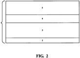
- Figure 2 shows another embodiment of the instant invention. In this alternative embodiment, one of the two terminals 2 is eliminated. This allows for multiple units thereof to stacked on top of each other to form larger multi-cell bipolar batteries.
- bipolar design is to increase the power by increase the contact area between cells.
- This design using Al foil connecting cells together through large area contact will reduce the internal impedance from 5 m ⁇ to 0.5 m ⁇ .
- the thickness of the separator will depend on the smoothness of the negative electrode.
- the roughness of the negative electrode can be controlled below 1 micron. Therefore, an oxide made by spin-coat sol gel process can be as thin as 2 microns and still be able to cover the surface of negative electrode.
- the impedance through this ultra-thin solid electrolyte can be minimal.
- the overall power density of this new device may be between 5,000 and 10,000 Watt per Kg.
- the battery would require less than 2 grams of MgNi negative electrode active material plus binder, less than 2.4 grams of ⁇ -phase nickel hydroxide, 0.2 grams of oxide separator, 0.2 grams of Al foil, and negligible weight from the plastic battery can.
- a 1.5 Wh battery can be created with less than 5 gram of material.
- the gravimetric energy density of such a battery is 300 Wh/kg.
- the cost of the negative electrode (particularly Mg-Ni) can be very low.
- the positive electrode will contain no Co which is used extensively in conventional Ni-MH and Li-ion batteries.
- the overall raw material cost for the 1.5 Wh battery described above would be: 2.6 cents for 2 g Mg-Ni ($13/kg), 2.9 cents for 2.4 g NiOOH ($12/kg), 1 cent for 0.2 g Oxide ($50/kg), 0.04 cents ($2.1/kg) plus some plastic.
- the total raw material cost is less than 7 cents for 1.5 Wh. So the raw material cost for this high energy, high power battery pack will be $47 per kWh.
- soli-state battery fo the present invention While specific methods/process of fabricating the soli-state battery fo the present invention have been described above, other processes are within the realm of the present invention.
- Other contemplated deposition processes include, but are not limited to, sputtering, evaporation, chemical vapor deposition (CVD), microwave plasma enhanced CVD (PECVD), radio frequency PECVD, physical vapor deposition (PVD), plasma enhanced PVD, laser ablation, spray coating, and plasma spraying.
- CVD chemical vapor deposition
- PECVD microwave plasma enhanced CVD
- PVD physical vapor deposition
- plasma enhanced PVD laser ablation
- spray coating and plasma spraying.
- the choice of deposition process will depend upon many factors such as materials to be deposited, precursor starting materials used, pressures/vacuums required by the process, cost, electrochemical and physical quality of deposited materials, and others.
Landscapes
- Chemical & Material Sciences (AREA)
- Chemical Kinetics & Catalysis (AREA)
- Electrochemistry (AREA)
- General Chemical & Material Sciences (AREA)
- Engineering & Computer Science (AREA)
- Manufacturing & Machinery (AREA)
- Inorganic Chemistry (AREA)
- Materials Engineering (AREA)
- Battery Electrode And Active Subsutance (AREA)
- Secondary Cells (AREA)
- Primary Cells (AREA)
- Conductive Materials (AREA)
- Battery Mounting, Suspending (AREA)
- Connection Of Batteries Or Terminals (AREA)
Claims (15)
- Batterie NiMH à l'état solide comprenant au moins une cellule de batterie multicouche comprenant :1) une couche à l'état solide (3) de matériau d'électrode négative capable d'adsorber et de désorber des protons pendant la charge et la décharge ;2) une couche à l'état solide (5) d'un matériau d'électrode positive capable de désorber et adsorber des protons pendant la charge et la décharge ;3) une couche à l'état solide (4) de matériau d'oxyde de type pérovskite disposée entre ladite couche (5) d'un matériau d'électrode positive et ladite couche (3) de matériau d'électrode négative, ladite couche (4) de matériau d'oxyde de type pérovskite est électriquement isoler et capable de conduire ou de transporter facilement des protons de ladite couche (5) de matériau d'électrode positive vers ladite couche (3) de matériau d'électrode négative pendant que ladite batterie est en charge et de ladite couche (3) de matériau d'électrode négative vers ladite couche (5) de matériau d'électrode positive pendant que ladite batterie est en décharge.
- Batterie NiMH à l'état solide selon la revendication 1, dans laquelle ladite couche (3) de matériau d'électrode négative, ladite couche (5) de matériau d'électrode positive et ladite couche (4) de matériau d'oxyde de type pérovskite sont toutes des matériaux en film mince.
- Batterie NiMH à l'état solide selon la revendication 2, dans laquelle ladite couche (5) de matériau d'électrode positive comprend un hydroxyde de métal de transition.
- Batterie NiMH à l'état solide selon la revendication 3, dans laquelle ledit hydroxyde de métal de transition est un matériau d'hydroxyde de nickel qui fournit approximativement un transfert d'électrons.
- Batterie NiMH à l'état solide selon la revendication 3, dans laquelle ledit matériau d'hydroxyde de nickel est un hydroxyde de nickel en phase γ qui fournit au moins 1,7 transfert d'électrons.
- Batterie NiMH à l'état solide selon la revendication 2, dans laquelle ladite couche (3) de matériau d'électrode négative est un matériau d'hydrure de métal.
- Batterie NiMH à l'état solide selon la revendication 6, dans laquelle ladite couche (3) de matériau d'électrode négative est désordonnée.
- Batterie NiMH à l'état solide selon la revendication 6, dans laquelle ladite couche (3) de matériau d'électrode négative est un matériau multiphasé, qui comprend une ou plusieurs phases amorphes, nanocristallines, microcristallines ou polycristallines.
- Batterie NiMH à l'état solide selon la revendication 6, dans laquelle ladite couche (3) de matériau d'électrode négative comprend un matériau d'alliage de stockage d'hydrogène de type Mg-Ni.
- Batterie NiMH à l'état solide selon la revendication 1, dans laquelle ledit matériau d'oxyde de type pérovskite comprend un ou plusieurs éléments choisis dans le groupe constitué par Ba, Sr, Zr, Sc, Y, La, Ce, Pr, Nd, Pm, Sm, Eu, Gd, Tb, Dy, Ho, Er, Tm, Yb, Lu, Fe, Cr, Al, Ti, Mg, Sn et In.
- Batterie NiMH à l'état solide selon la revendication 1, dans laquelle ladite au moins une cellule de batterie multicouche comprend en outre des couches terminales de batterie (2) inférieure et supérieure électriquement conductrices adjacentes auxdites couches à l'état solide (3, 5) de matériau d'électrode négative et de matériau d'électrode positive et éloignées de ladite couche à l'état solide (4) de matériau d'oxyde de type pérovskite.
- Batterie NiMH à l'état solide selon la revendication 11, dans laquelle lesdites couches terminales de batterie (2) inférieure et supérieure électriquement conductrices sont formées à partir d'un métal électriquement conducteur choisi dans le groupe constitué par l'aluminium, le nickel, le cuivre et des alliages, des mélanges ou des composites de ceux-ci.
- Batterie NiMH à l'état solide selon la revendication 12, dans laquelle lesdites couches terminales de batterie (2) inférieure et supérieure électriquement conductrices sont formées à partir d'aluminium.
- Batterie NiMH à l'état solide selon la revendication 11, dans laquelle lesdites couches terminales de batterie (2) inférieure et supérieure électriquement conductrices sont formées à partir d'une céramique électriquement conductrice ou d'un matériau d'oxyde électriquement conducteur.
- Batterie NiMH à l'état solide selon la revendication 1 comprenant :plus d'une desdites cellules de batterie multicouche et comprenant en outre :des couches terminales de batterie (2) déposées entre ladite couche (5) de matériau d'électrode positive d'une cellule de batterie multicouche et ladite couche (3) de matériau d'électrode négative d'une cellule de batterie multicouche adjacente.
Applications Claiming Priority (2)
| Application Number | Priority Date | Filing Date | Title |
|---|---|---|---|
| US33623910P | 2010-01-19 | 2010-01-19 | |
| PCT/US2011/000086 WO2011090779A2 (fr) | 2010-01-19 | 2011-01-18 | Batteries économiques bipolaires à hydrure métallique, à électrolyte solide, à haute densité d'énergie et de grande puissance |
Publications (3)
| Publication Number | Publication Date |
|---|---|
| EP2526587A2 EP2526587A2 (fr) | 2012-11-28 |
| EP2526587A4 EP2526587A4 (fr) | 2014-06-11 |
| EP2526587B1 true EP2526587B1 (fr) | 2017-01-11 |
Family
ID=44307505
Family Applications (1)
| Application Number | Title | Priority Date | Filing Date |
|---|---|---|---|
| EP11734955.5A Active EP2526587B1 (fr) | 2010-01-19 | 2011-01-18 | Batteries économiques bipolaires à nickel-hydrure métallique, à électrolyte solide, à haute densité d'énergie et de grande puissance |
Country Status (5)
| Country | Link |
|---|---|
| EP (1) | EP2526587B1 (fr) |
| JP (1) | JP5774606B2 (fr) |
| KR (1) | KR101688258B1 (fr) |
| CN (1) | CN102792508A (fr) |
| WO (1) | WO2011090779A2 (fr) |
Families Citing this family (22)
| Publication number | Priority date | Publication date | Assignee | Title |
|---|---|---|---|---|
| US10987735B2 (en) | 2015-12-16 | 2021-04-27 | 6K Inc. | Spheroidal titanium metallic powders with custom microstructures |
| CA3009630C (fr) | 2015-12-16 | 2023-08-01 | Amastan Technologies Llc | Metaux deshydrogenes spheroidaux et particules d'alliage metallique |
| JP7021102B2 (ja) * | 2016-03-28 | 2022-02-16 | ビーエーエスエフ コーポレーション | 充電式電池用のシリコンに基づく固体電解質 |
| KR102072884B1 (ko) * | 2016-07-22 | 2020-02-03 | 주식회사 엘지화학 | 유-무기 복합 태양전지용 적층체 제조방법 및 유무기 복합 태양전지 제조방법 |
| CN109004219A (zh) * | 2017-06-07 | 2018-12-14 | 银隆新能源股份有限公司 | 一种包含稀土改性钡钛复合氧化物的锂离子电池 |
| CN109962282B (zh) * | 2017-12-14 | 2022-02-11 | 中国科学院大连化学物理研究所 | 一种采用质子嵌入化合物的可充电电池 |
| CN112654444A (zh) | 2018-06-19 | 2021-04-13 | 6K有限公司 | 由原材料制造球化粉末的方法 |
| JP7122981B2 (ja) * | 2019-01-31 | 2022-08-22 | 株式会社日本マイクロニクス | 二次電池 |
| SG11202111576QA (en) | 2019-04-30 | 2021-11-29 | 6K Inc | Mechanically alloyed powder feedstock |
| CN114641462A (zh) | 2019-11-18 | 2022-06-17 | 6K有限公司 | 用于球形粉末的独特原料及制造方法 |
| US11590568B2 (en) | 2019-12-19 | 2023-02-28 | 6K Inc. | Process for producing spheroidized powder from feedstock materials |
| WO2021199642A1 (fr) * | 2020-03-31 | 2021-10-07 | パナソニックIpマネジメント株式会社 | Matériau d'électrolyte solide et batterie l'utilisant |
| CA3180426A1 (fr) | 2020-06-25 | 2021-12-30 | Richard K. Holman | Structure d'alliage microcomposite |
| AU2021349358A1 (en) | 2020-09-24 | 2023-02-09 | 6K Inc. | Systems, devices, and methods for starting plasma |
| CA3196653A1 (fr) | 2020-10-30 | 2022-05-05 | Sunil Bhalchandra BADWE | Systemes et procedes de synthese de poudres metalliques spheroidales |
| AU2022206483A1 (en) | 2021-01-11 | 2023-08-31 | 6K Inc. | Methods and systems for reclamation of li-ion cathode materials using microwave plasma processing |
| WO2022212291A1 (fr) | 2021-03-31 | 2022-10-06 | 6K Inc. | Systèmes et procédés de fabrication additive de céramiques de nitrure métallique |
| CN117546335A (zh) * | 2021-06-21 | 2024-02-09 | 川崎摩托株式会社 | 质子传导性充电电池及方法 |
| WO2023229928A1 (fr) | 2022-05-23 | 2023-11-30 | 6K Inc. | Appareil à plasma à micro-ondes et procédés de traitement de matériaux à l'aide d'un revêtement intérieur |
| US12040162B2 (en) | 2022-06-09 | 2024-07-16 | 6K Inc. | Plasma apparatus and methods for processing feed material utilizing an upstream swirl module and composite gas flows |
| WO2024044498A1 (fr) | 2022-08-25 | 2024-02-29 | 6K Inc. | Appareil à plasma et procédés de traitement de matériau d'alimentation à l'aide d'un dispositif de prévention d'entrée de poudre (pip) |
| US12195338B2 (en) | 2022-12-15 | 2025-01-14 | 6K Inc. | Systems, methods, and device for pyrolysis of methane in a microwave plasma for hydrogen and structured carbon powder production |
Family Cites Families (19)
| Publication number | Priority date | Publication date | Assignee | Title |
|---|---|---|---|---|
| JPS60211778A (ja) * | 1984-03-14 | 1985-10-24 | Sharp Corp | 固体電解質電池 |
| JPS63158761A (ja) * | 1986-12-19 | 1988-07-01 | Sanyo Electric Co Ltd | 固体水素電池 |
| US6287432B1 (en) * | 1987-03-13 | 2001-09-11 | The Standard Oil Company | Solid multi-component membranes, electrochemical reactor components, electrochemical reactors and use of membranes, reactor components, and reactor for oxidation reactions |
| US5300371A (en) * | 1990-03-23 | 1994-04-05 | Battery Technologies Inc. | Manganese dioxide positive electrode for rechargeable cells, and cells containing the same |
| JPH05180397A (ja) * | 1991-12-27 | 1993-07-20 | Sanyo Electric Co Ltd | 水素輸送船 |
| US5567549A (en) * | 1992-11-12 | 1996-10-22 | Ovonic Battery Company, Inc. | Nickel metal hydride battery containing a modified disordered multiphase nickel aluminum based positive electrode |
| US5411592A (en) * | 1994-06-06 | 1995-05-02 | Ovonic Battery Company, Inc. | Apparatus for deposition of thin-film, solid state batteries |
| JPH10226836A (ja) * | 1997-02-14 | 1998-08-25 | Matsushita Electric Ind Co Ltd | 水素吸蔵合金およびその製造方法 |
| JP3489960B2 (ja) * | 1997-04-01 | 2004-01-26 | 松下電器産業株式会社 | アルカリ蓄電池 |
| US6967183B2 (en) * | 1998-08-27 | 2005-11-22 | Cabot Corporation | Electrocatalyst powders, methods for producing powders and devices fabricated from same |
| US7141528B2 (en) * | 1998-08-27 | 2006-11-28 | Cabot Corporation | Electrocatalyst powders, methods for producing powders and devices fabricated from same |
| JP2000265234A (ja) * | 1999-03-16 | 2000-09-26 | Tdk Corp | 水素吸蔵合金およびその製造方法と二次電池 |
| US6994807B2 (en) * | 2002-09-24 | 2006-02-07 | Corning Incorporated | Electrolytic perovskites |
| JP2007506226A (ja) * | 2003-09-15 | 2007-03-15 | コニンクリユケ フィリップス エレクトロニクス エヌ.ブイ. | 電気化学エネルギー源、電子装置及び同エネルギー源の製造方法 |
| JP4381273B2 (ja) * | 2004-10-01 | 2009-12-09 | 株式会社東芝 | 二次電池及び二次電池の製造方法 |
| JP4984518B2 (ja) * | 2005-12-19 | 2012-07-25 | トヨタ自動車株式会社 | 燃料電池の製造方法 |
| EP2041827A2 (fr) * | 2006-07-03 | 2009-04-01 | Koninklijke Philips Electronics N.V. | Procédé pour la fabrication d'une source d'énergie électrochimique à pellicule mince et dispositif associé |
| JP5061544B2 (ja) * | 2006-09-05 | 2012-10-31 | トヨタ自動車株式会社 | 燃料電池 |
| TW200919803A (en) * | 2007-06-07 | 2009-05-01 | Koninkl Philips Electronics Nv | Solid-state battery and method for manufacturing of such a solid-state battery |
-
2011
- 2011-01-18 EP EP11734955.5A patent/EP2526587B1/fr active Active
- 2011-01-18 KR KR1020127021630A patent/KR101688258B1/ko active Active
- 2011-01-18 WO PCT/US2011/000086 patent/WO2011090779A2/fr not_active Ceased
- 2011-01-18 CN CN2011800147886A patent/CN102792508A/zh active Pending
- 2011-01-18 JP JP2012550009A patent/JP5774606B2/ja active Active
Non-Patent Citations (1)
| Title |
|---|
| None * |
Also Published As
| Publication number | Publication date |
|---|---|
| WO2011090779A3 (fr) | 2011-11-10 |
| KR101688258B1 (ko) | 2016-12-20 |
| KR20120129914A (ko) | 2012-11-28 |
| JP2013517614A (ja) | 2013-05-16 |
| JP5774606B2 (ja) | 2015-09-09 |
| CN102792508A (zh) | 2012-11-21 |
| WO2011090779A2 (fr) | 2011-07-28 |
| EP2526587A4 (fr) | 2014-06-11 |
| EP2526587A2 (fr) | 2012-11-28 |
Similar Documents
| Publication | Publication Date | Title |
|---|---|---|
| EP2526587B1 (fr) | Batteries économiques bipolaires à nickel-hydrure métallique, à électrolyte solide, à haute densité d'énergie et de grande puissance | |
| US8974948B2 (en) | Low cost, high power, high energy density, solid-state, bipolar metal hydride batteries | |
| Karimzadeh et al. | Emerging atomic layer deposition for the development of high-performance lithium-ion batteries | |
| US20250046865A1 (en) | Method for Suppressing Metal Propagation in Solid Electrolytes | |
| CA2177056C (fr) | Pile seche a electrolyte ionique ou protonique | |
| US5376475A (en) | Aqueous lithium-hydrogen ion rechargeable battery | |
| US8808916B2 (en) | Cathode active material for lithium secondary batteries, method for preparing the same, and lithium secondary batteries comprising the same | |
| US20220131125A1 (en) | Surface coated porous substrates and particles and systems and methods thereof | |
| JP2006511907A (ja) | 高エネルギー密度高出力密度電気化学電池 | |
| WO2005076389A9 (fr) | Anodes autoporteuses a film mince de type a alliage destinees aux batteries a ions de lithium | |
| CN104466146A (zh) | 非水电解质二次电池及电池包 | |
| US20210351411A1 (en) | Secondary battery and method of preparing the same | |
| JP2025530804A (ja) | 固体電解質、及びその製造方法、二次電池、電池モジュール、電池パック及び電力消費装置 | |
| Kim et al. | Thin‐Film Batteries for On‐Chip and Wearable Applications: Advances, Challenges, and Future Perspectives | |
| US11641032B2 (en) | Solid electrolyte, method for producing solid electrolyte, and composite body | |
| WO2025255997A1 (fr) | Batterie secondaire et dispositif électrique | |
| US12166169B2 (en) | Solid electrolyte, method for producing solid electrolyte, and composite body | |
| CN110462889A (zh) | 锂离子薄膜微电池及其制造方法 | |
| EP0867050A1 (fr) | Accumulateur solide a electrode negative de carbone hydrogene desordonnee | |
| KR102108781B1 (ko) | 신규한 리튬 복합금속 산화물 및 이를 포함하는 리튬 이차전지 | |
| US11641031B2 (en) | Solid electrolyte, method for producing solid electrolyte, and composite body | |
| WO2026031731A1 (fr) | Batterie secondaire au sodium, matériau actif d'électrode positive et son procédé de préparation, et dispositif électrique | |
| TW202401876A (zh) | 用於鋰離子電池銅電流導體上之平面矽陽極 | |
| CN114050309A (zh) | 全固态锂离子电池、制备方法和电子装置 |
Legal Events
| Date | Code | Title | Description |
|---|---|---|---|
| PUAI | Public reference made under article 153(3) epc to a published international application that has entered the european phase |
Free format text: ORIGINAL CODE: 0009012 |
|
| 17P | Request for examination filed |
Effective date: 20120718 |
|
| AK | Designated contracting states |
Kind code of ref document: A2 Designated state(s): AL AT BE BG CH CY CZ DE DK EE ES FI FR GB GR HR HU IE IS IT LI LT LU LV MC MK MT NL NO PL PT RO RS SE SI SK SM TR |
|
| DAX | Request for extension of the european patent (deleted) | ||
| A4 | Supplementary search report drawn up and despatched |
Effective date: 20140509 |
|
| RIC1 | Information provided on ipc code assigned before grant |
Ipc: H01M 2/26 20060101ALI20140502BHEP Ipc: H01M 4/48 20100101ALI20140502BHEP Ipc: H01M 10/34 20060101ALI20140502BHEP Ipc: H01M 10/04 20060101ALI20140502BHEP Ipc: H01M 4/38 20060101ALI20140502BHEP Ipc: H01M 10/05 20100101AFI20140502BHEP |
|
| GRAP | Despatch of communication of intention to grant a patent |
Free format text: ORIGINAL CODE: EPIDOSNIGR1 |
|
| INTG | Intention to grant announced |
Effective date: 20160425 |
|
| GRAP | Despatch of communication of intention to grant a patent |
Free format text: ORIGINAL CODE: EPIDOSNIGR1 |
|
| INTG | Intention to grant announced |
Effective date: 20160803 |
|
| GRAS | Grant fee paid |
Free format text: ORIGINAL CODE: EPIDOSNIGR3 |
|
| GRAA | (expected) grant |
Free format text: ORIGINAL CODE: 0009210 |
|
| AK | Designated contracting states |
Kind code of ref document: B1 Designated state(s): AL AT BE BG CH CY CZ DE DK EE ES FI FR GB GR HR HU IE IS IT LI LT LU LV MC MK MT NL NO PL PT RO RS SE SI SK SM TR |
|
| REG | Reference to a national code |
Ref country code: GB Ref legal event code: FG4D |
|
| REG | Reference to a national code |
Ref country code: CH Ref legal event code: EP |
|
| REG | Reference to a national code |
Ref country code: AT Ref legal event code: REF Ref document number: 862036 Country of ref document: AT Kind code of ref document: T Effective date: 20170115 |
|
| REG | Reference to a national code |
Ref country code: IE Ref legal event code: FG4D |
|
| REG | Reference to a national code |
Ref country code: DE Ref legal event code: R096 Ref document number: 602011034263 Country of ref document: DE |
|
| REG | Reference to a national code |
Ref country code: FR Ref legal event code: PLFP Year of fee payment: 7 |
|
| REG | Reference to a national code |
Ref country code: LT Ref legal event code: MG4D |
|
| REG | Reference to a national code |
Ref country code: NL Ref legal event code: MP Effective date: 20170111 |
|
| PG25 | Lapsed in a contracting state [announced via postgrant information from national office to epo] |
Ref country code: BE Free format text: LAPSE BECAUSE OF NON-PAYMENT OF DUE FEES Effective date: 20170131 |
|
| REG | Reference to a national code |
Ref country code: AT Ref legal event code: MK05 Ref document number: 862036 Country of ref document: AT Kind code of ref document: T Effective date: 20170111 |
|
| PG25 | Lapsed in a contracting state [announced via postgrant information from national office to epo] |
Ref country code: NL Free format text: LAPSE BECAUSE OF FAILURE TO SUBMIT A TRANSLATION OF THE DESCRIPTION OR TO PAY THE FEE WITHIN THE PRESCRIBED TIME-LIMIT Effective date: 20170111 |
|
| PG25 | Lapsed in a contracting state [announced via postgrant information from national office to epo] |
Ref country code: IS Free format text: LAPSE BECAUSE OF FAILURE TO SUBMIT A TRANSLATION OF THE DESCRIPTION OR TO PAY THE FEE WITHIN THE PRESCRIBED TIME-LIMIT Effective date: 20170511 Ref country code: GR Free format text: LAPSE BECAUSE OF FAILURE TO SUBMIT A TRANSLATION OF THE DESCRIPTION OR TO PAY THE FEE WITHIN THE PRESCRIBED TIME-LIMIT Effective date: 20170412 Ref country code: HR Free format text: LAPSE BECAUSE OF FAILURE TO SUBMIT A TRANSLATION OF THE DESCRIPTION OR TO PAY THE FEE WITHIN THE PRESCRIBED TIME-LIMIT Effective date: 20170111 Ref country code: LT Free format text: LAPSE BECAUSE OF FAILURE TO SUBMIT A TRANSLATION OF THE DESCRIPTION OR TO PAY THE FEE WITHIN THE PRESCRIBED TIME-LIMIT Effective date: 20170111 Ref country code: NO Free format text: LAPSE BECAUSE OF FAILURE TO SUBMIT A TRANSLATION OF THE DESCRIPTION OR TO PAY THE FEE WITHIN THE PRESCRIBED TIME-LIMIT Effective date: 20170411 Ref country code: FI Free format text: LAPSE BECAUSE OF FAILURE TO SUBMIT A TRANSLATION OF THE DESCRIPTION OR TO PAY THE FEE WITHIN THE PRESCRIBED TIME-LIMIT Effective date: 20170111 |
|
| PG25 | Lapsed in a contracting state [announced via postgrant information from national office to epo] |
Ref country code: PT Free format text: LAPSE BECAUSE OF FAILURE TO SUBMIT A TRANSLATION OF THE DESCRIPTION OR TO PAY THE FEE WITHIN THE PRESCRIBED TIME-LIMIT Effective date: 20170511 Ref country code: SE Free format text: LAPSE BECAUSE OF FAILURE TO SUBMIT A TRANSLATION OF THE DESCRIPTION OR TO PAY THE FEE WITHIN THE PRESCRIBED TIME-LIMIT Effective date: 20170111 Ref country code: RS Free format text: LAPSE BECAUSE OF FAILURE TO SUBMIT A TRANSLATION OF THE DESCRIPTION OR TO PAY THE FEE WITHIN THE PRESCRIBED TIME-LIMIT Effective date: 20170111 Ref country code: BG Free format text: LAPSE BECAUSE OF FAILURE TO SUBMIT A TRANSLATION OF THE DESCRIPTION OR TO PAY THE FEE WITHIN THE PRESCRIBED TIME-LIMIT Effective date: 20170411 Ref country code: LV Free format text: LAPSE BECAUSE OF FAILURE TO SUBMIT A TRANSLATION OF THE DESCRIPTION OR TO PAY THE FEE WITHIN THE PRESCRIBED TIME-LIMIT Effective date: 20170111 Ref country code: PL Free format text: LAPSE BECAUSE OF FAILURE TO SUBMIT A TRANSLATION OF THE DESCRIPTION OR TO PAY THE FEE WITHIN THE PRESCRIBED TIME-LIMIT Effective date: 20170111 Ref country code: ES Free format text: LAPSE BECAUSE OF FAILURE TO SUBMIT A TRANSLATION OF THE DESCRIPTION OR TO PAY THE FEE WITHIN THE PRESCRIBED TIME-LIMIT Effective date: 20170111 Ref country code: AT Free format text: LAPSE BECAUSE OF FAILURE TO SUBMIT A TRANSLATION OF THE DESCRIPTION OR TO PAY THE FEE WITHIN THE PRESCRIBED TIME-LIMIT Effective date: 20170111 |
|
| REG | Reference to a national code |
Ref country code: CH Ref legal event code: PL |
|
| REG | Reference to a national code |
Ref country code: DE Ref legal event code: R097 Ref document number: 602011034263 Country of ref document: DE |
|
| PG25 | Lapsed in a contracting state [announced via postgrant information from national office to epo] |
Ref country code: IT Free format text: LAPSE BECAUSE OF FAILURE TO SUBMIT A TRANSLATION OF THE DESCRIPTION OR TO PAY THE FEE WITHIN THE PRESCRIBED TIME-LIMIT Effective date: 20170111 Ref country code: RO Free format text: LAPSE BECAUSE OF FAILURE TO SUBMIT A TRANSLATION OF THE DESCRIPTION OR TO PAY THE FEE WITHIN THE PRESCRIBED TIME-LIMIT Effective date: 20170111 Ref country code: LI Free format text: LAPSE BECAUSE OF NON-PAYMENT OF DUE FEES Effective date: 20170131 Ref country code: CZ Free format text: LAPSE BECAUSE OF FAILURE TO SUBMIT A TRANSLATION OF THE DESCRIPTION OR TO PAY THE FEE WITHIN THE PRESCRIBED TIME-LIMIT Effective date: 20170111 Ref country code: EE Free format text: LAPSE BECAUSE OF FAILURE TO SUBMIT A TRANSLATION OF THE DESCRIPTION OR TO PAY THE FEE WITHIN THE PRESCRIBED TIME-LIMIT Effective date: 20170111 Ref country code: SK Free format text: LAPSE BECAUSE OF FAILURE TO SUBMIT A TRANSLATION OF THE DESCRIPTION OR TO PAY THE FEE WITHIN THE PRESCRIBED TIME-LIMIT Effective date: 20170111 Ref country code: CH Free format text: LAPSE BECAUSE OF NON-PAYMENT OF DUE FEES Effective date: 20170131 |
|
| REG | Reference to a national code |
Ref country code: IE Ref legal event code: MM4A |
|
| PLBE | No opposition filed within time limit |
Free format text: ORIGINAL CODE: 0009261 |
|
| STAA | Information on the status of an ep patent application or granted ep patent |
Free format text: STATUS: NO OPPOSITION FILED WITHIN TIME LIMIT |
|
| PG25 | Lapsed in a contracting state [announced via postgrant information from national office to epo] |
Ref country code: DK Free format text: LAPSE BECAUSE OF FAILURE TO SUBMIT A TRANSLATION OF THE DESCRIPTION OR TO PAY THE FEE WITHIN THE PRESCRIBED TIME-LIMIT Effective date: 20170111 Ref country code: MC Free format text: LAPSE BECAUSE OF FAILURE TO SUBMIT A TRANSLATION OF THE DESCRIPTION OR TO PAY THE FEE WITHIN THE PRESCRIBED TIME-LIMIT Effective date: 20170111 Ref country code: LU Free format text: LAPSE BECAUSE OF NON-PAYMENT OF DUE FEES Effective date: 20170118 Ref country code: SM Free format text: LAPSE BECAUSE OF FAILURE TO SUBMIT A TRANSLATION OF THE DESCRIPTION OR TO PAY THE FEE WITHIN THE PRESCRIBED TIME-LIMIT Effective date: 20170111 |
|
| 26N | No opposition filed |
Effective date: 20171012 |
|
| REG | Reference to a national code |
Ref country code: FR Ref legal event code: PLFP Year of fee payment: 8 |
|
| REG | Reference to a national code |
Ref country code: BE Ref legal event code: MM Effective date: 20170131 |
|
| PG25 | Lapsed in a contracting state [announced via postgrant information from national office to epo] |
Ref country code: IE Free format text: LAPSE BECAUSE OF NON-PAYMENT OF DUE FEES Effective date: 20170118 Ref country code: SI Free format text: LAPSE BECAUSE OF FAILURE TO SUBMIT A TRANSLATION OF THE DESCRIPTION OR TO PAY THE FEE WITHIN THE PRESCRIBED TIME-LIMIT Effective date: 20170111 |
|
| PG25 | Lapsed in a contracting state [announced via postgrant information from national office to epo] |
Ref country code: MT Free format text: LAPSE BECAUSE OF NON-PAYMENT OF DUE FEES Effective date: 20170118 |
|
| PG25 | Lapsed in a contracting state [announced via postgrant information from national office to epo] |
Ref country code: HU Free format text: LAPSE BECAUSE OF FAILURE TO SUBMIT A TRANSLATION OF THE DESCRIPTION OR TO PAY THE FEE WITHIN THE PRESCRIBED TIME-LIMIT; INVALID AB INITIO Effective date: 20110118 |
|
| PG25 | Lapsed in a contracting state [announced via postgrant information from national office to epo] |
Ref country code: CY Free format text: LAPSE BECAUSE OF NON-PAYMENT OF DUE FEES Effective date: 20170111 |
|
| PG25 | Lapsed in a contracting state [announced via postgrant information from national office to epo] |
Ref country code: MK Free format text: LAPSE BECAUSE OF FAILURE TO SUBMIT A TRANSLATION OF THE DESCRIPTION OR TO PAY THE FEE WITHIN THE PRESCRIBED TIME-LIMIT Effective date: 20170111 |
|
| PG25 | Lapsed in a contracting state [announced via postgrant information from national office to epo] |
Ref country code: TR Free format text: LAPSE BECAUSE OF FAILURE TO SUBMIT A TRANSLATION OF THE DESCRIPTION OR TO PAY THE FEE WITHIN THE PRESCRIBED TIME-LIMIT Effective date: 20170111 |
|
| PG25 | Lapsed in a contracting state [announced via postgrant information from national office to epo] |
Ref country code: AL Free format text: LAPSE BECAUSE OF FAILURE TO SUBMIT A TRANSLATION OF THE DESCRIPTION OR TO PAY THE FEE WITHIN THE PRESCRIBED TIME-LIMIT Effective date: 20170111 |
|
| P01 | Opt-out of the competence of the unified patent court (upc) registered |
Effective date: 20230315 |
|
| PGFP | Annual fee paid to national office [announced via postgrant information from national office to epo] |
Ref country code: GB Payment date: 20260126 Year of fee payment: 16 |
|
| PGFP | Annual fee paid to national office [announced via postgrant information from national office to epo] |
Ref country code: DE Payment date: 20260127 Year of fee payment: 16 |
|
| PGFP | Annual fee paid to national office [announced via postgrant information from national office to epo] |
Ref country code: FR Payment date: 20260126 Year of fee payment: 16 |