EP2526794B1 - Hand joint supporter - Google Patents
Hand joint supporter Download PDFInfo
- Publication number
- EP2526794B1 EP2526794B1 EP11734798.9A EP11734798A EP2526794B1 EP 2526794 B1 EP2526794 B1 EP 2526794B1 EP 11734798 A EP11734798 A EP 11734798A EP 2526794 B1 EP2526794 B1 EP 2526794B1
- Authority
- EP
- European Patent Office
- Prior art keywords
- section
- knitted fabric
- hand
- tubular knitted
- wearer
- Prior art date
- Legal status (The legal status is an assumption and is not a legal conclusion. Google has not performed a legal analysis and makes no representation as to the accuracy of the status listed.)
- Active
Links
Images





Classifications
-
- A—HUMAN NECESSITIES
- A61—MEDICAL OR VETERINARY SCIENCE; HYGIENE
- A61F—FILTERS IMPLANTABLE INTO BLOOD VESSELS; PROSTHESES; DEVICES PROVIDING PATENCY TO, OR PREVENTING COLLAPSING OF, TUBULAR STRUCTURES OF THE BODY, e.g. STENTS; ORTHOPAEDIC, NURSING OR CONTRACEPTIVE DEVICES; FOMENTATION; TREATMENT OR PROTECTION OF EYES OR EARS; BANDAGES, DRESSINGS OR ABSORBENT PADS; FIRST-AID KITS
- A61F5/00—Orthopaedic methods or devices for non-surgical treatment of bones or joints; Nursing devices ; Anti-rape devices
- A61F5/01—Orthopaedic devices, e.g. long-term immobilising or pressure directing devices for treating broken or deformed bones such as splints, casts or braces
- A61F5/0102—Orthopaedic devices, e.g. long-term immobilising or pressure directing devices for treating broken or deformed bones such as splints, casts or braces specially adapted for correcting deformities of the limbs or for supporting them; Ortheses, e.g. with articulations
- A61F5/013—Orthopaedic devices, e.g. long-term immobilising or pressure directing devices for treating broken or deformed bones such as splints, casts or braces specially adapted for correcting deformities of the limbs or for supporting them; Ortheses, e.g. with articulations for the arms, hands or fingers
-
- A—HUMAN NECESSITIES
- A41—WEARING APPAREL
- A41D—OUTERWEAR; PROTECTIVE GARMENTS; ACCESSORIES
- A41D13/00—Professional, industrial or sporting protective garments, e.g. surgeons' gowns or garments protecting against blows or punches
-
- A—HUMAN NECESSITIES
- A41—WEARING APPAREL
- A41D—OUTERWEAR; PROTECTIVE GARMENTS; ACCESSORIES
- A41D13/00—Professional, industrial or sporting protective garments, e.g. surgeons' gowns or garments protecting against blows or punches
- A41D13/05—Professional, industrial or sporting protective garments, e.g. surgeons' gowns or garments protecting against blows or punches protecting only a particular body part
- A41D13/08—Arm or hand
-
- A—HUMAN NECESSITIES
- A41—WEARING APPAREL
- A41D—OUTERWEAR; PROTECTIVE GARMENTS; ACCESSORIES
- A41D13/00—Professional, industrial or sporting protective garments, e.g. surgeons' gowns or garments protecting against blows or punches
- A41D13/05—Professional, industrial or sporting protective garments, e.g. surgeons' gowns or garments protecting against blows or punches protecting only a particular body part
- A41D13/08—Arm or hand
- A41D13/081—Hand protectors
- A41D13/088—Hand protectors especially for the wrist
-
- A—HUMAN NECESSITIES
- A41—WEARING APPAREL
- A41F—GARMENT FASTENINGS; SUSPENDERS
- A41F5/00—Trouser supports attached to the shirt, waistcoat, or the like
-
- A—HUMAN NECESSITIES
- A61—MEDICAL OR VETERINARY SCIENCE; HYGIENE
- A61F—FILTERS IMPLANTABLE INTO BLOOD VESSELS; PROSTHESES; DEVICES PROVIDING PATENCY TO, OR PREVENTING COLLAPSING OF, TUBULAR STRUCTURES OF THE BODY, e.g. STENTS; ORTHOPAEDIC, NURSING OR CONTRACEPTIVE DEVICES; FOMENTATION; TREATMENT OR PROTECTION OF EYES OR EARS; BANDAGES, DRESSINGS OR ABSORBENT PADS; FIRST-AID KITS
- A61F13/00—Bandages or dressings; Absorbent pads
- A61F13/10—Bandages or dressings; Absorbent pads specially adapted for fingers, hands or arms; Finger-stalls; Nail-protectors
- A61F13/104—Bandages or dressings; Absorbent pads specially adapted for fingers, hands or arms; Finger-stalls; Nail-protectors for the hands or fingers
-
- A—HUMAN NECESSITIES
- A61—MEDICAL OR VETERINARY SCIENCE; HYGIENE
- A61F—FILTERS IMPLANTABLE INTO BLOOD VESSELS; PROSTHESES; DEVICES PROVIDING PATENCY TO, OR PREVENTING COLLAPSING OF, TUBULAR STRUCTURES OF THE BODY, e.g. STENTS; ORTHOPAEDIC, NURSING OR CONTRACEPTIVE DEVICES; FOMENTATION; TREATMENT OR PROTECTION OF EYES OR EARS; BANDAGES, DRESSINGS OR ABSORBENT PADS; FIRST-AID KITS
- A61F13/00—Bandages or dressings; Absorbent pads
- A61F13/10—Bandages or dressings; Absorbent pads specially adapted for fingers, hands or arms; Finger-stalls; Nail-protectors
- A61F13/107—Bandages or dressings; Absorbent pads specially adapted for fingers, hands or arms; Finger-stalls; Nail-protectors for wrist support ; Compression devices for tennis elbow (epicondylitis)
-
- D—TEXTILES; PAPER
- D04—BRAIDING; LACE-MAKING; KNITTING; TRIMMINGS; NON-WOVEN FABRICS
- D04B—KNITTING
- D04B1/00—Weft knitting processes for the production of fabrics or articles not dependent on the use of particular machines; Fabrics or articles defined by such processes
- D04B1/10—Patterned fabrics or articles
- D04B1/102—Patterned fabrics or articles with stitch pattern
-
- D—TEXTILES; PAPER
- D04—BRAIDING; LACE-MAKING; KNITTING; TRIMMINGS; NON-WOVEN FABRICS
- D04B—KNITTING
- D04B1/00—Weft knitting processes for the production of fabrics or articles not dependent on the use of particular machines; Fabrics or articles defined by such processes
- D04B1/14—Other fabrics or articles characterised primarily by the use of particular thread materials
- D04B1/18—Other fabrics or articles characterised primarily by the use of particular thread materials elastic threads
-
- D—TEXTILES; PAPER
- D04—BRAIDING; LACE-MAKING; KNITTING; TRIMMINGS; NON-WOVEN FABRICS
- D04B—KNITTING
- D04B1/00—Weft knitting processes for the production of fabrics or articles not dependent on the use of particular machines; Fabrics or articles defined by such processes
- D04B1/22—Weft knitting processes for the production of fabrics or articles not dependent on the use of particular machines; Fabrics or articles defined by such processes specially adapted for knitting goods of particular configuration
-
- A—HUMAN NECESSITIES
- A41—WEARING APPAREL
- A41D—OUTERWEAR; PROTECTIVE GARMENTS; ACCESSORIES
- A41D2500/00—Materials for garments
- A41D2500/10—Knitted
-
- D—TEXTILES; PAPER
- D10—INDEXING SCHEME ASSOCIATED WITH SUBLASSES OF SECTION D, RELATING TO TEXTILES
- D10B—INDEXING SCHEME ASSOCIATED WITH SUBLASSES OF SECTION D, RELATING TO TEXTILES
- D10B2509/00—Medical; Hygiene
- D10B2509/02—Bandages, dressings or absorbent pads
- D10B2509/028—Elastic support stockings or elastic bandages
Definitions
- the present invention relates to a hand joint supporter which can support wearer's daily motion, and particularly, to a hand joint supporter having a taping function of improving stability of the hand joints, thereby reducing the burden on the hand joints and also preventing an inflammation of the tendons of the hand.
- JP 2005-549 A shows a supporter for wrist restraint which has a supporter main body which is formed in an approximately tubular shape, can expand and contract at least in the circumferential direction among the circumferential direction and the longitudinal direction, and can cover a site from the vicinity of the wrist of the forearm section to at least the vicinity of the bases of the four fingers except for the thumb, an opening portion for the thumb formed in the supporter main body, and a support which extends along the longitudinal direction on the little finger side of the supporter main body inserted into a pocket, wherein the support is provided so as to be able to extend from at least the vicinity of the wrist of the forearm section on which the support is mounted, to the side portion on the little finger side of the palm over a pisiform bone site.
- WO 00/67600 A1 discloses a fabric compression glove comprising at least one adapted portion which is integrally incorporated into the fabric of the glove and has an extensibility differing from that in the adjacent parts of the glove which offers improved conformability.
- JP 3 104396 U discloses a glove made of an elastic cylinder of prescribed length having formed one opening at one end for the four fingers excluding the thumb, and having a through-hole for the thumb.
- the supporter for wrist restraint in the related art is a supporter for restraining the movement of the wrist as a conservative therapy in a case where a bruise, a sprain, or an inflammation of the tendon develops in the wrist, and is not provided with a support on the thumb side and the back side of the hand and the palm side of the hand.
- a support which bends when an external force or a load is added thereto is also included.
- it is regarded as being formed so that the fixed feeling is not lost by the bending, and is formed of, for example, synthetic resin, metal, carbon fiber, glass fiber, wood, or the like.
- the present invention has been made to solve the problem as described above.
- the hand joints of the wearer are stabilized by performing the inhibiting of the palmar flexion and/or the dorsal flexion of the hand joints, and a load which is applied to a tendon that is located at the hand joints is reduced, so that an inflammation of the tendons of the hand can be prevented.
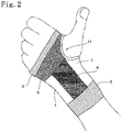
- a hand joint supporter 10 is made of a tubular knitted fabric which is knitted by circular knitting by a hosiery knitting machine (for example, a type of knitting machine (the number of needles: 256) manufactured by Lonati Co.), and is a supporter which comes into close contact with the body surface of the wearer, thereby assisting the hand joints of the wearer.
- a hosiery knitting machine for example, a type of knitting machine (the number of needles: 256) manufactured by Lonati Co.
- the hand joint supporter 10 has a desired function such as a taping function by performing different knitting with respect to a base fabric section 1 that is a knitted fabric which is knitted in a plain stitch, a rib stitch, a tuck stitch, a float stitch, a pile stitch, or the like by using an upper thread, an under thread, and a rubber thread as knitting yarn.
- the base fabric section 1 related to this embodiment is a knitted fabric which is knitted in a tuck stitch (hereinafter referred to as a tuck stitch knitted fabric).
- the tuck stitch knitted fabric is a knitted fabric in which a certain loop is not made temporarily when knitting the fabric and loops are made together when knitting the next course.
- the number of tucks is set to be twice. However, the number is not limited thereto.
- the hand joint supporter 10 has a first anchor section 2 which is knitted to go around one end (an upper end 10a) of the tubular knitted fabric and makes the hand joint supporter 10 tighten on the forearm of a wearer.
- the first anchor section 2 is knitted such that the stretch resistance thereof in the circumferential direction H of the hand joint supporter 10 (the tubular knitted fabric) is larger than the stretch resistance of the base fabric section 1 in the circumferential direction H of the hand joint supporter 10. That is, when tension in a case where a certain elongation has been imparted to a material from a state where elongation is not imparted is set to be F, the tension of the base fabric section 1 in the circumferential direction H of the hand joint supporter 10 is set to be F H1 , and the tension of the first anchor section 2 in the circumferential direction H of the hand joint supporter 10 is set to be F H2 , the first anchor section 2 has such a magnitude relationship of F H2 >F H1 that it has a strong tightening force in the circumferential direction H of the hand joint supporter 10, compared to the base fabric section 1.
- the first anchor section 2 be a knitted fabric knitted in a moss stitch (hereinafter referred to as a moss stitch knitted fabric), it is possible to make the stretch resistance thereof in the circumferential direction H of the hand joint supporter 10 large with respect to the base fabric section 1 that is the tuck stitch knitted fabric.
- a moss stitch knitted fabric a knitted fabric knitted in a moss stitch
- the moss stitch knitted fabric is a knitted fabric in which a plain stitch and a tuck (a structure in which no loop protrudes over a given course and a plurality of loops protrude over the subsequent course) appear alternately or every few courses in the course direction and the wale direction.
- the plain stitch and the tuck are used in combination, whereby it is possible to make protuberances or openwork stitches on the surface of a knitted fabric and a mesh pattern, such as a moss, appears.
- the first anchor section 2 is knitted to surround the forearm of a wearer, and the stretch resistance of the first anchor section 2 in the circumferential direction H of the hand joint supporter 10 is larger than the stretch resistance of the base fabric section 1 in the circumferential direction H of the hand joint supporter 10, whereby it is possible to fix the hand joint supporter 10 to the forearm of a wearer and suppress slipping-off of the upper end 10a of the hand joint supporter 10 during palmar flexion of the hand joints.
- the first anchor section 2 is connected to a supporting section 4 (described later), thereby also functioning as an anchor of the supporting section 4.
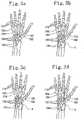
- the hand joint supporter 10 has a second anchor section 3 which is knitted to go around the other end (a lower end 10b) of the tubular knitted fabric, surrounds portions corresponding to a second metacarpal bone 102, a third metacarpal bone 103, a fourth metacarpal bone 104, and a fifth metacarpal bone 105 in the vicinity of metacarpophalangeal joints 110 of a wearer, and makes the hand joint supporter 10 tighten on the palm and the back of the hand of the wearer, as shown in Fig. 3(a) .
- the second anchor section 3 is knitted such that the stretch resistance thereof in the circumferential direction H of the hand joint supporter 10 is larger than the stretch resistance of a buffer section 5 (described later) in the circumferential direction H of the hand joint supporter 10. That is, when the tension of the second anchor section 3 in the circumferential direction H of the hand joint supporter 10 is set to be F H3 and the tension of the buffer section 5 in the circumferential direction H of the hand joint supporter 10 is set to be F H5 , the second anchor section 3 has such a magnitude relationship of F H3 >F H5 that it has a strong tightening force in the circumferential direction H of the hand joint supporter 10, compared to the buffer section 5.
- the second anchor section 3 be a moss stitch knitted fabric, it is possible to make the stretch resistance thereof in the circumferential direction H of the hand joint supporter 10 large with respect to the buffer section 5 that is a mesh stitch knitted fabric which will be described later.
- the second anchor section 3 is knitted to surround the palm and the back of the hand of a wearer and the stretch resistance of the second anchor section 3 in the circumferential direction H of the hand joint supporter 10 is larger than the stretch resistance of the buffer section 5 in the circumferential direction H of the hand joint supporter 10, whereby it is possible to fix the hand joint supporter 10 to the palm and the back of the hand of a wearer and suppress slipping-off of the lower end 10b of the hand joint supporter 10 during palmar flexion of the hand joints.
- the gaps between the fingers (the second finger (the index finger or the forefinger), the third finger (the middle finger), the fourth finger (the ring finger), and the fifth finger (the little finger)) of the hand of a wearer cannot be fully opened, thereby causing interference with work such as keyboard operation of a personal computer.
- the hand joint supporter 10 related to this embodiment is made such that the density of the second anchor section 3 is adjusted (for example, to make a tightening force thereof about 10% smaller with respect to the first anchor section 2), whereby the movement of the fingers of the hand with the hand joint supporter 10 worn thereon is not prevented. That is, it is preferable that the hand joint supporter 10 related to this embodiment have a magnitude relationship of F H2 >F H1 >F H3 >F H5 so as to have a moderate tightening force in the circumferential direction H of the hand joint supporter 10.
- a hole anchor section 11 is formed as an approximately circular through-hole in the vicinity of the second anchor section 3 in the hand joint supporter 10 to insert the first finger (the thumb or the big finger) of the hand of a wearer therethrough.
- the hole anchor section 11 related to this embodiment is made by making a cut in the tubular knitted fabric which becomes the hand joint supporter 10, folding a cut edge back to the inside of the tubular knitted fabric, and sewing it using a sewing machine.
- the hole anchor section 11 may also be formed by knitting without cutting out the tubular knitted fabric.
- a sewn section constituting the hole anchor section 11 be formed as a flexible bellows by using a sewing thread having high stretch property and increasing the number of stitches per inch of the sewing machine, to reduce a pressing force which is imparted on the thumb of a wearer.
- the hole anchor section 11 positions the hand joint supporter 10 with respect to the hand joints of the wearer by inserting the thumb of the hand of the wearer therethrough and also suppresses the rotational movement in the circumferential direction H or the parallel displacement in the length direction L of the hand joint supporter 10, thereby being able to prevent a position shift. Further, the hole anchor section 11 is connected to the supporting section 4 (described later), thereby also functioning as an anchor of the supporting section 4.
- the supporting section 4 is knitted to extend in the length direction L of the hand joint supporter 10 over portions corresponding to carpometacarpal joints 120 of a wearer on the front face and/or back face side of the hand joint supporter 10 and is connected to the first anchor section 2 and the hole anchor section 11, thereby supporting the hand joints of the wearer. That is, the supporting section 4 is locked at the first anchor section 2 on the forearm side of a wearer and locked at the hole anchor section 11 on the hand side of the wearer.
- the supporting section 4 related to this embodiment is knitted in an approximately rectangular shape.
- the shape thereof is not limited thereto.
- the supporting section 4 is knitted such that the stretch resistance thereof in the length direction L of the hand joint supporter 10 is larger than the stretch resistance of the base fabric section 1 in the length direction L of the hand joint supporter 10. That is, when the tension of the base fabric section 1 in the length direction L of the hand joint supporter 10 is set to be F L1 and the tension of the supporting section 4 in the length direction L of the hand joint supporter 10 is set to be F L4 , the supporting section 4 has such a magnitude relationship of F L4 >F L1 that it has a strong tightening force in the length direction L of the hand joint supporter 10, compared to the base fabric section 1.
- the supporting section 4 be a knitted fabric in which a tuck stitch and a plating stitch are used in combination (hereinafter referred to as a tuck stitch-plating stitch knitted fabric), it is possible to make the stretch resistance in the length direction L of the hand joint supporter 10 large with respect to the base fabric section 1 that is a tuck stitch knitted fabric.
- expansion and contraction of the supporting section 4 in the length direction L of the hand joint supporter 10 is moderately suppressed by additionally feeding another knitting yarn (for example, woolly nylon yarn) in addition to the ground knitting yarn of the tuck stitch, and another knitting yarn is cut at the boundary between the supporting section 4 and the base fabric section 1 (a cut boss).
- another knitting yarn for example, woolly nylon yarn
- the supporting section 4 is knitted to extend in the length direction L of the hand joint supporter 10 over the portions corresponding to carpometacarpal joints 120 of the wearer on the front face and/or back face side of the hand joint supporter 10, and the stretch resistance in the length direction L of the hand joint supporter 10 is larger than the stretch resistance of the base fabric section 1 in the length direction L of the hand joint supporter 10.
- the supporting section 4 limits the palmar flexion and/or the dorsal flexion of the hand joints of a wearer, thereby being able to secure stability of the hand joints and also reduce the load that is applied to a tendon which is located at the hand joints.
- the supporting section 4 is disposed on the front face (the palm of the hand) side of the hand joint supporter 10, thereby limiting the dorsal flexion of the hand joints of the wearer, and is disposed on the back face (the back of the hand) side of the hand joint supporter 10, thereby limiting the palmar flexion of the hand joint of the wearer.
- the hand joint supporter 10 in which the supporting section 4 is disposed only on the front face (the palm of the hand) side is also acceptable, and in the case of wanting to limit the palmar flexion of the hand joints, the hand joint supporter 10 in which the supporting section 4 is disposed only on the back face (the back of the hand) side is also acceptable.
- the hand joint supporter 10 it is preferable to dispose the supporting sections 4 on the front face and back face sides of the hand joint supporter 10, because the front face and the back face of the hand joint supporter 10 become symmetrical, so that the hand joint supporter 10 can double as left-hand and right-hand supporters.
- the supporting section 4 along with the base fabric section 1 which is knitted between the supporting sections 4 that are on the front face and back face sides of the tubular knitted fabric extends only from the vicinity (the first anchor section 2) of radiocarpal joints 130 to the vicinity of the carpometacarpal joints 120, as shown in Fig. 3(c) , a holding feeling of the wrist cannot be obtained and the above-described operation and effects by the supporting section 4 cannot be obtained.
- the supporting section 4 and the base fabric section 1 extend from the vicinity (the first anchor section 2) of the radiocarpal joints 130 to the metacarpal bone bodies (the approximate middles of the second metacarpal bone 102, the third metacarpal bone 103, the fourth metacarpal bone 104, and the fifth metacarpal bone 105), as shown in Fig. 3(b) .
- radial flexion and ulnar flexion are included, and the radial flexion and the ulnar flexion are motions which are frequently used in daily life, and according to the motion, the frequency of occurrence of De Quervain syndrome that is an inflammation of the tendons extending toward the thumb from the hand is high.
- the supporting section 4 and the base fabric section 1 limit the radial flexion and the ulnar flexion of the hand joints of a wearer, whereby prevention and improvement of De Quervain syndrome can be expected.
- the buffer section 5 is a knitted fabric surrounded by the second anchor section 3, the hole anchor section 11, the supporting section 4, and the base fabric section 1 in the hand joint supporter 10 and is a knitted fabric making flexibility be provided between the second anchor section 3 and the supporting section 4.
- the buffer section 5 is knitted such that the stretch resistance thereof in the length direction L of the hand joint supporter 10 is smaller than the stretch resistance of the base fabric section 1 in the length direction L of the hand joint supporter 10. That is, when the tension of the buffer section 5 in the length direction L of the hand joint supporter 10 is set to be F L5 , the buffer section 5 has such a magnitude relationship of F L1 >F L5 that it has a weak tightening force in the length direction L of the hand joint supporter 10, compared to the base fabric section 1.
- the buffer section 5 be a knitted fabric knitted in a mesh stitch that is a knitting structure having good air permeability (hereinafter referred to as a mesh stitch knitted fabric), it is possible to make the stretch resistance in the length direction L of the hand joint supporter 10 small with respect to the base fabric section 1 that is a tuck stitch knitted fabric.
- a mesh stitch knitted fabric a knitted fabric knitted in a mesh stitch that is a knitting structure having good air permeability
- the mesh stitch knitted fabric is a knitted fabric in which a certain loop is not made temporarily when knitting the fabric and loops are made together when knitting the next course and which stretches well by being knit in the form of a mesh.
- the stretch resistance thereof in the length direction L of the hand joint supporter 10 is smaller than the stretch resistance of the base fabric section 1 in the length direction L of the hand joint supporter 10, whereby the buffer section 5 does not tighten the palm and the back of the hand of the wearer, thereby preventing constriction of blood flow as well as allowing the gaps between the fingers of a wearer to be fully open, so that a feeling of discomfort is not caused to the wearer.
- the stretch resistance of the base fabric section 1 in the length direction L of the hand joint supporter 10 is larger than the stretch resistance of the first anchor section 2 in the length direction L of the hand joint supporter 10. Further, the stretch resistance of the first anchor section 2 in the length direction L of the hand joint supporter 10 is larger than the stretch resistance of the second anchor section 3 in the length direction L of the hand joint supporter 10. Further, the stretch resistance of the second anchor section 3 in the length direction L of the hand joint supporter 10 is larger than the stretch resistance of the buffer section 5 in the length direction L of the hand joint supporter 10. Further, the stretch resistance of the supporting section 4 in the circumferential direction H of the hand joint supporter 10 is approximately equal to the stretch resistance of the base fabric section 1 in the circumferential direction H of the hand joint supporter 10.
- the hand joint supporter 10 related to this embodiment satisfies a magnitude relationship shown by the following expression (1) in the tension F in the length direction L of the hand joint supporter 10.
- F L2 is the tension of the first anchor section 2 in the length direction L of the hand joint supporter
- F L3 is the tension of the second anchor section 3 in the length direction L of the hand joint supporter 10.
- the hand joint supporter 10 related to this embodiment satisfies a magnitude relationship shown by the following expression (2) in the tension F in the circumferential direction H of the hand joint supporter 10.
- F H4 is the tension of the supporting section 4 in the circumferential direction H of the hand joint supporter 10.
- DCY double covered yarn
- the upper thread it is preferable to select a natural fiber such as cotton, wool (cashmere, lamb, Angora, or the like), silk, or hemp, a chemical fiber such as acrylic, a material having a sweat absorbing, quick-drying, or body temperature adjusting function, or the like according to the cost of the hand joint supporter 10 or the needs of a wearer.
- a natural fiber such as cotton, wool (cashmere, lamb, Angora, or the like)
- silk or hemp
- a chemical fiber such as acrylic
- a material having a sweat absorbing, quick-drying, or body temperature adjusting function, or the like according to the cost of the hand joint supporter 10 or the needs of a wearer.
- a chemical fiber such as the under thread, it is preferable to select an ester, FTY (filament twisted yarn), or an antibacterial, deodorant, or odor eliminating material according to the cost of the hand joint supporter 10 or the needs of a wearer.
- the woolly nylon yarn (pattern yarn) in the tuck stitch-plating stitch knitted fabric (the supporting section 4) is composed of two pieces of knitting yarn each having a thickness of 100 deniers.
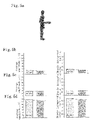
- the myogenic potentials of the biceps brachii muscle (the muscle which bends the elbow) and the flexor carpi ulnaris muscle and the flexor carpi radialis muscle (the muscles which bend the wrist) for the final 5 seconds were measured by a surface electromyogram ( Fig. 5 ).
- "MyoResearch” manufactured by Noraxon, Inc. was used in the measurement of the surface electromyogram.
- Figs. 5(b) and 5(c) it can be seen that in the case of the time of wear, compared to the case of the time of non-wear, since the myogenic potentials (the average amplitudes and the muscle integrated values) of the flexor carpi ulnaris muscle and the flexor carpi radialis muscle are lowered, loads on the flexor carpi ulnaris muscle and the flexor carpi radialis muscle are reduced, so that the burden on the hand joints is reduced.
- the hand joint supporter 10 reduces the burden on the hand joints, thereby being able to prevent an inflammation of the tendonds of the hand.
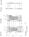
- Fig. 8(a) is a front view showing the schematic configuration of a hand joint supporter related to the second embodiment
- Fig. 8(b) is a back view of the hand joint supporter shown in Fig. 8(a)
- Fig. 8(c) is a left side view of the hand joint supporter shown in Fig. 8(a)
- Fig. 8(d) is a right side view of the hand joint supporter shown in Fig. 8(a)
- Fig. 8(e) is a plan view and bottom view of the hand joint supporter shown in Fig. 8(a)
- Fig. 9(a) is a front view showing the schematic configuration of another hand joint supporter related to the second embodiment
- Fig. 9(a) is a front view showing the schematic configuration of another hand joint supporter related to the second embodiment
- FIG. 9(b) is a back view of the hand joint supporter shown in Fig. 9(a)
- Fig. 9(c) is a left side view of the hand joint supporter shown in Fig. 9(a)
- Fig. 9(d) is a right side view of the hand joint supporter shown in Fig. 9(a)
- Fig. 9(e) is a plan view and bottom view of the hand joint supporter shown in Fig. 9(a)
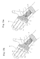
- Fig. 10(a) is a perspective view showing a wearing state of the hand joint supporter shown in Fig. 8
- Fig. 10(b) is a perspective view showing a wearing state of the hand joint supporter shown in Fig. 9 .
- the same symbol as that in Figs. 1 and 2 denotes the same or equivalent section, and explanation thereof is omitted.
- the hand joint supporter 10 related to this embodiment is configured to have, in addition to the configuration in the first embodiment, an anchor reinforcing section 12 which is made of a second tubular knitted fabric that is knitted by circular knitting continuously from the second anchor section 3 of the tubular knitted fabric and which spans between the palm and the back of the hand of a wearer in the webbing between the index finger and the middle finger of the wearer, the webbing between the middle finger and the ring finger, and/or the webbing between the ring finger and the little finger, thereby being engaged with the webbing of the wearer.
- an anchor reinforcing section 12 which is made of a second tubular knitted fabric that is knitted by circular knitting continuously from the second anchor section 3 of the tubular knitted fabric and which spans between the palm and the back of the hand of a wearer in the webbing between the index finger and the middle finger of the wearer, the webbing between the middle finger and the ring finger, and/or the webbing between the ring finger and the little finger, thereby being engaged
- a mesh stitch knitted fabric which stretches well is used as the second tubular knitted fabric, whereby a strong pressing force is not imparted to the webbing between the index finger and the middle finger of the wearer, the webbing between the middle finger and the ring finger, and/or the webbing between the ring finger and the little finger, so that a feeling of discomfort is not induced in the wearer.
- the anchor reinforcing section 12 related to this embodiment has, for example, two engagement portions (a first engagement portion 12a and a second engagement portion 12b) which are engaged with the webbing between the index finger and the middle finger of a wearer and the webbing between the ring finger and the little finger, as shown in Figs. 8 and 10(a) , or three engagement portions (a first engagement portion 12a, a third engagement portion 12c, and a second engagement portion 12b) which are engaged with the webbing between the index finger and the middle finger of a wearer, the webbing between the middle finger and the ring finger, and the webbing between the ring finger and the little finger, as shown in Figs. 9 and 10(b) .
- the hand joint supporter 10 shown in Figs. 9 and 10(b) covers each finger up to the vicinity of the proximal interphalangeal joints of the index finger, the middle finger, the ring finger, and the little finger of a wearer and the number of engagements of the engagement portions of the anchor reinforcing section 12 with the webbings of a wearer is large, so that the contact area with the fingers of the wearer is large, it is possible to stably support the hand joints of the wearer.
- the hand joint supporter 10 related to this embodiment more reliably supports the hand joints of a wearer by hooking the engagement portions of the anchor reinforcing section 12 on a single or a plurality of webbings, so that the burden on the hand joints is reduced, whereby an inflammation of the tendons of the hand can be prevented.
- the second embodiment is different from the first embodiment only in that the anchor reinforcing section 12 having a single or a plurality of engagement portions is newly disposed at the second anchor section 3 of the hand joint supporter 10, and except the above-described operation and effects by the anchor reinforcing section 12, the same operation and effects as those of the first embodiment are obtained.
Landscapes
- Health & Medical Sciences (AREA)
- Engineering & Computer Science (AREA)
- General Health & Medical Sciences (AREA)
- Textile Engineering (AREA)
- Veterinary Medicine (AREA)
- Public Health (AREA)
- Biomedical Technology (AREA)
- Heart & Thoracic Surgery (AREA)
- Vascular Medicine (AREA)
- Life Sciences & Earth Sciences (AREA)
- Animal Behavior & Ethology (AREA)
- Physical Education & Sports Medicine (AREA)
- Nursing (AREA)
- Orthopedic Medicine & Surgery (AREA)
- Rheumatology (AREA)
- Professional, Industrial, Or Sporting Protective Garments (AREA)
- Orthopedics, Nursing, And Contraception (AREA)
- Prostheses (AREA)
Applications Claiming Priority (2)
| Application Number | Priority Date | Filing Date | Title |
|---|---|---|---|
| JP2010012510 | 2010-01-22 | ||
| PCT/JP2011/051218 WO2011090192A1 (ja) | 2010-01-22 | 2011-01-24 | 手関節サポーター |
Publications (3)
| Publication Number | Publication Date |
|---|---|
| EP2526794A1 EP2526794A1 (en) | 2012-11-28 |
| EP2526794A4 EP2526794A4 (en) | 2014-01-08 |
| EP2526794B1 true EP2526794B1 (en) | 2022-09-14 |
Family
ID=44306993
Family Applications (1)
| Application Number | Title | Priority Date | Filing Date |
|---|---|---|---|
| EP11734798.9A Active EP2526794B1 (en) | 2010-01-22 | 2011-01-24 | Hand joint supporter |
Country Status (9)
| Country | Link |
|---|---|
| US (2) | US20120283610A1 (pl) |
| EP (1) | EP2526794B1 (pl) |
| JP (1) | JP5543496B2 (pl) |
| KR (1) | KR101557385B1 (pl) |
| CN (1) | CN102724891B (pl) |
| ES (1) | ES2929400T3 (pl) |
| PL (1) | PL2526794T3 (pl) |
| TW (1) | TWI501756B (pl) |
| WO (1) | WO2011090192A1 (pl) |
Families Citing this family (8)
| Publication number | Priority date | Publication date | Assignee | Title |
|---|---|---|---|---|
| CA2939932C (en) * | 2014-03-03 | 2022-11-29 | Kowa Company, Ltd. | Wrist joint bandage |
| WO2016100794A1 (en) * | 2014-12-18 | 2016-06-23 | Ing Source, Inc. | Compression wrist garment, and therapeutic method for reducing wrist pain |
| US12324759B2 (en) | 2018-05-02 | 2025-06-10 | Nanyang Technological University | Brace for a body joint and method of manufacturing thereof |
| TWI832896B (zh) * | 2018-09-13 | 2024-02-21 | 日商興和股份有限公司 | 支撐物 |
| CN110144667A (zh) * | 2019-06-13 | 2019-08-20 | 浙江百翔科技有限公司 | 一种手套的生产工艺 |
| CN111759572B (zh) * | 2020-06-15 | 2022-05-03 | 延安大学附属医院 | 手部吊挂器 |
| IT202200009362A1 (it) | 2022-05-06 | 2023-11-06 | Laura Cortinovis | Indumento contenitivo e relativo metodo di produzione |
| FR3161104A1 (fr) | 2024-04-16 | 2025-10-17 | Thuasne | Orthèse de pouce, en particulier pour soulager et/ou traiter la rhizarthrose, procédé de fabrication d’une telle orthèse |
Family Cites Families (18)
| Publication number | Priority date | Publication date | Assignee | Title |
|---|---|---|---|---|
| US2403201A (en) * | 1942-03-16 | 1946-07-02 | Wildt & Co Ltd | Knitted fabric |
| US2910852A (en) * | 1957-06-03 | 1959-11-03 | Charles N Herbert | Knitted hosiery |
| US2872800A (en) * | 1958-02-04 | 1959-02-10 | Charleston Hosiery Proc Compan | Circular knit fabric with raised areas |
| US4961418A (en) * | 1987-03-26 | 1990-10-09 | Mclaurin Smith Mark | Heat retaining fabric and physical therapy appliances |
| US4967419A (en) * | 1989-10-13 | 1990-11-06 | Elliott Grady N | Arm protector |
| JP2894778B2 (ja) * | 1990-03-05 | 1999-05-24 | アルケア株式会社 | サポーター |
| JPH0751140B2 (ja) * | 1992-12-24 | 1995-06-05 | 泰一郎 岩倉 | 腱鞘炎予防手袋 |
| JP3695774B2 (ja) * | 1993-12-14 | 2005-09-14 | 川上 哲宏 | 手袋 |
| TW356428B (en) * | 1993-12-14 | 1999-04-21 | Hisatomi Kk | Wrist restrainer and wrist restraining glove |
| US7200872B2 (en) * | 1994-10-05 | 2007-04-10 | Kathryn Gregory | Article of thermal clothing for covering the underlying area at the gap between a coat sleeve and a glove |
| US5810753A (en) * | 1995-03-27 | 1998-09-22 | Eberbach; Mark A. | Glove |
| DE19651912A1 (de) * | 1996-12-13 | 1998-06-18 | Beiersdorf Ag | Anatomisch geformte medizinische Bandagen |
| JPH10295870A (ja) * | 1997-04-24 | 1998-11-10 | Shinji Kunihiro | 手腕保護用サポーター |
| GB9910576D0 (en) * | 1999-05-08 | 1999-07-07 | Smith & Nephew | Compression gloves |
| JP4189660B2 (ja) | 2003-06-13 | 2008-12-03 | 小林製薬株式会社 | 手首拘束用サポーター |
| JP3104396U (ja) * | 2004-04-01 | 2004-09-16 | 株式会社ナカイ | ハンドウオーマー |
| DE102004036344B4 (de) | 2004-07-27 | 2007-05-24 | Bsn-Jobst Gmbh | Strickware zum Stützen und/oder Komprimieren und/oder Kompressionsbehandlung von Körperteilen und Verfahren zur Herstellung einer solchen Strickware |
| US7485111B1 (en) * | 2006-06-05 | 2009-02-03 | Eugene Choi | Medicated sleeve |
-
2011
- 2011-01-21 TW TW100102422A patent/TWI501756B/zh active
- 2011-01-24 KR KR1020127018166A patent/KR101557385B1/ko active Active
- 2011-01-24 US US13/522,612 patent/US20120283610A1/en not_active Abandoned
- 2011-01-24 WO PCT/JP2011/051218 patent/WO2011090192A1/ja not_active Ceased
- 2011-01-24 CN CN201180006675.1A patent/CN102724891B/zh active Active
- 2011-01-24 EP EP11734798.9A patent/EP2526794B1/en active Active
- 2011-01-24 PL PL11734798.9T patent/PL2526794T3/pl unknown
- 2011-01-24 ES ES11734798T patent/ES2929400T3/es active Active
- 2011-01-24 JP JP2011550979A patent/JP5543496B2/ja active Active
-
2015
- 2015-02-23 US US14/628,929 patent/US9579229B2/en active Active
Also Published As
| Publication number | Publication date |
|---|---|
| CN102724891B (zh) | 2014-08-27 |
| KR101557385B1 (ko) | 2015-10-05 |
| ES2929400T3 (es) | 2022-11-29 |
| JPWO2011090192A1 (ja) | 2013-05-23 |
| JP5543496B2 (ja) | 2014-07-09 |
| HK1172521A1 (zh) | 2013-04-26 |
| WO2011090192A1 (ja) | 2011-07-28 |
| PL2526794T3 (pl) | 2023-01-30 |
| TWI501756B (zh) | 2015-10-01 |
| CN102724891A (zh) | 2012-10-10 |
| US20150164671A1 (en) | 2015-06-18 |
| US9579229B2 (en) | 2017-02-28 |
| TW201143728A (en) | 2011-12-16 |
| EP2526794A4 (en) | 2014-01-08 |
| KR20120118007A (ko) | 2012-10-25 |
| EP2526794A1 (en) | 2012-11-28 |
| US20120283610A1 (en) | 2012-11-08 |
Similar Documents
| Publication | Publication Date | Title |
|---|---|---|
| US9579229B2 (en) | Hand joint supporter | |
| EP2526792B1 (en) | Elbow joint supporter | |
| KR101557384B1 (ko) | 무릎 관절 서포터 | |
| US9526651B2 (en) | Lower leg supporter | |
| EP3412160A1 (en) | Knee supporter and garment | |
| CN102883688B (zh) | 织物绷带 | |
| US7491186B2 (en) | Wrist and elbow brace | |
| JP2012245117A (ja) | 膝関節サポーター | |
| HK1172521B (en) | Hand joint supporter | |
| WO2020054832A1 (ja) | サポーター | |
| JP7682438B2 (ja) | 母指用装具 | |
| WO2016100794A1 (en) | Compression wrist garment, and therapeutic method for reducing wrist pain | |
| HK1172520B (en) | Elbow joint supporter | |
| HK1172522B (en) | Knee joint supporter |
Legal Events
| Date | Code | Title | Description |
|---|---|---|---|
| PUAI | Public reference made under article 153(3) epc to a published international application that has entered the european phase |
Free format text: ORIGINAL CODE: 0009012 |
|
| 17P | Request for examination filed |
Effective date: 20120719 |
|
| AK | Designated contracting states |
Kind code of ref document: A1 Designated state(s): AL AT BE BG CH CY CZ DE DK EE ES FI FR GB GR HR HU IE IS IT LI LT LU LV MC MK MT NL NO PL PT RO RS SE SI SK SM TR |
|
| DAX | Request for extension of the european patent (deleted) | ||
| A4 | Supplementary search report drawn up and despatched |
Effective date: 20131210 |
|
| RIC1 | Information provided on ipc code assigned before grant |
Ipc: A61F 13/10 20060101ALI20131204BHEP Ipc: A41D 13/08 20060101AFI20131204BHEP Ipc: A41D 13/00 20060101ALI20131204BHEP |
|
| 17Q | First examination report despatched |
Effective date: 20150603 |
|
| STAA | Information on the status of an ep patent application or granted ep patent |
Free format text: STATUS: EXAMINATION IS IN PROGRESS |
|
| GRAP | Despatch of communication of intention to grant a patent |
Free format text: ORIGINAL CODE: EPIDOSNIGR1 |
|
| STAA | Information on the status of an ep patent application or granted ep patent |
Free format text: STATUS: GRANT OF PATENT IS INTENDED |
|
| INTG | Intention to grant announced |
Effective date: 20220412 |
|
| GRAS | Grant fee paid |
Free format text: ORIGINAL CODE: EPIDOSNIGR3 |
|
| GRAA | (expected) grant |
Free format text: ORIGINAL CODE: 0009210 |
|
| STAA | Information on the status of an ep patent application or granted ep patent |
Free format text: STATUS: THE PATENT HAS BEEN GRANTED |
|
| AK | Designated contracting states |
Kind code of ref document: B1 Designated state(s): AL AT BE BG CH CY CZ DE DK EE ES FI FR GB GR HR HU IE IS IT LI LT LU LV MC MK MT NL NO PL PT RO RS SE SI SK SM TR |
|
| RAP3 | Party data changed (applicant data changed or rights of an application transferred) |
Owner name: KOWA COMPANY, LTD. |
|
| REG | Reference to a national code |
Ref country code: GB Ref legal event code: FG4D |
|
| REG | Reference to a national code |
Ref country code: CH Ref legal event code: EP |
|
| REG | Reference to a national code |
Ref country code: DE Ref legal event code: R096 Ref document number: 602011073274 Country of ref document: DE |
|
| REG | Reference to a national code |
Ref country code: IE Ref legal event code: FG4D |
|
| REG | Reference to a national code |
Ref country code: AT Ref legal event code: REF Ref document number: 1518170 Country of ref document: AT Kind code of ref document: T Effective date: 20221015 |
|
| REG | Reference to a national code |
Ref country code: ES Ref legal event code: FG2A Ref document number: 2929400 Country of ref document: ES Kind code of ref document: T3 Effective date: 20221129 |
|
| REG | Reference to a national code |
Ref country code: LT Ref legal event code: MG9D |
|
| REG | Reference to a national code |
Ref country code: NL Ref legal event code: MP Effective date: 20220914 |
|
| PG25 | Lapsed in a contracting state [announced via postgrant information from national office to epo] |
Ref country code: SE Free format text: LAPSE BECAUSE OF FAILURE TO SUBMIT A TRANSLATION OF THE DESCRIPTION OR TO PAY THE FEE WITHIN THE PRESCRIBED TIME-LIMIT Effective date: 20220914 Ref country code: RS Free format text: LAPSE BECAUSE OF FAILURE TO SUBMIT A TRANSLATION OF THE DESCRIPTION OR TO PAY THE FEE WITHIN THE PRESCRIBED TIME-LIMIT Effective date: 20220914 Ref country code: NO Free format text: LAPSE BECAUSE OF FAILURE TO SUBMIT A TRANSLATION OF THE DESCRIPTION OR TO PAY THE FEE WITHIN THE PRESCRIBED TIME-LIMIT Effective date: 20221214 Ref country code: LV Free format text: LAPSE BECAUSE OF FAILURE TO SUBMIT A TRANSLATION OF THE DESCRIPTION OR TO PAY THE FEE WITHIN THE PRESCRIBED TIME-LIMIT Effective date: 20220914 Ref country code: LT Free format text: LAPSE BECAUSE OF FAILURE TO SUBMIT A TRANSLATION OF THE DESCRIPTION OR TO PAY THE FEE WITHIN THE PRESCRIBED TIME-LIMIT Effective date: 20220914 Ref country code: FI Free format text: LAPSE BECAUSE OF FAILURE TO SUBMIT A TRANSLATION OF THE DESCRIPTION OR TO PAY THE FEE WITHIN THE PRESCRIBED TIME-LIMIT Effective date: 20220914 |
|
| PG25 | Lapsed in a contracting state [announced via postgrant information from national office to epo] |
Ref country code: HR Free format text: LAPSE BECAUSE OF FAILURE TO SUBMIT A TRANSLATION OF THE DESCRIPTION OR TO PAY THE FEE WITHIN THE PRESCRIBED TIME-LIMIT Effective date: 20220914 Ref country code: GR Free format text: LAPSE BECAUSE OF FAILURE TO SUBMIT A TRANSLATION OF THE DESCRIPTION OR TO PAY THE FEE WITHIN THE PRESCRIBED TIME-LIMIT Effective date: 20221215 |
|
| PG25 | Lapsed in a contracting state [announced via postgrant information from national office to epo] |
Ref country code: SM Free format text: LAPSE BECAUSE OF FAILURE TO SUBMIT A TRANSLATION OF THE DESCRIPTION OR TO PAY THE FEE WITHIN THE PRESCRIBED TIME-LIMIT Effective date: 20220914 Ref country code: RO Free format text: LAPSE BECAUSE OF FAILURE TO SUBMIT A TRANSLATION OF THE DESCRIPTION OR TO PAY THE FEE WITHIN THE PRESCRIBED TIME-LIMIT Effective date: 20220914 Ref country code: PT Free format text: LAPSE BECAUSE OF FAILURE TO SUBMIT A TRANSLATION OF THE DESCRIPTION OR TO PAY THE FEE WITHIN THE PRESCRIBED TIME-LIMIT Effective date: 20230116 Ref country code: CZ Free format text: LAPSE BECAUSE OF FAILURE TO SUBMIT A TRANSLATION OF THE DESCRIPTION OR TO PAY THE FEE WITHIN THE PRESCRIBED TIME-LIMIT Effective date: 20220914 |
|
| PG25 | Lapsed in a contracting state [announced via postgrant information from national office to epo] |
Ref country code: SK Free format text: LAPSE BECAUSE OF FAILURE TO SUBMIT A TRANSLATION OF THE DESCRIPTION OR TO PAY THE FEE WITHIN THE PRESCRIBED TIME-LIMIT Effective date: 20220914 Ref country code: IS Free format text: LAPSE BECAUSE OF FAILURE TO SUBMIT A TRANSLATION OF THE DESCRIPTION OR TO PAY THE FEE WITHIN THE PRESCRIBED TIME-LIMIT Effective date: 20230114 Ref country code: EE Free format text: LAPSE BECAUSE OF FAILURE TO SUBMIT A TRANSLATION OF THE DESCRIPTION OR TO PAY THE FEE WITHIN THE PRESCRIBED TIME-LIMIT Effective date: 20220914 |
|
| REG | Reference to a national code |
Ref country code: DE Ref legal event code: R097 Ref document number: 602011073274 Country of ref document: DE |
|
| P01 | Opt-out of the competence of the unified patent court (upc) registered |
Effective date: 20230522 |
|
| PG25 | Lapsed in a contracting state [announced via postgrant information from national office to epo] |
Ref country code: NL Free format text: LAPSE BECAUSE OF FAILURE TO SUBMIT A TRANSLATION OF THE DESCRIPTION OR TO PAY THE FEE WITHIN THE PRESCRIBED TIME-LIMIT Effective date: 20220914 Ref country code: AL Free format text: LAPSE BECAUSE OF FAILURE TO SUBMIT A TRANSLATION OF THE DESCRIPTION OR TO PAY THE FEE WITHIN THE PRESCRIBED TIME-LIMIT Effective date: 20220914 |
|
| REG | Reference to a national code |
Ref country code: AT Ref legal event code: UEP Ref document number: 1518170 Country of ref document: AT Kind code of ref document: T Effective date: 20220914 |
|
| PLBE | No opposition filed within time limit |
Free format text: ORIGINAL CODE: 0009261 |
|
| STAA | Information on the status of an ep patent application or granted ep patent |
Free format text: STATUS: NO OPPOSITION FILED WITHIN TIME LIMIT |
|
| PG25 | Lapsed in a contracting state [announced via postgrant information from national office to epo] |
Ref country code: DK Free format text: LAPSE BECAUSE OF FAILURE TO SUBMIT A TRANSLATION OF THE DESCRIPTION OR TO PAY THE FEE WITHIN THE PRESCRIBED TIME-LIMIT Effective date: 20220914 |
|
| 26N | No opposition filed |
Effective date: 20230615 |
|
| PG25 | Lapsed in a contracting state [announced via postgrant information from national office to epo] |
Ref country code: SI Free format text: LAPSE BECAUSE OF FAILURE TO SUBMIT A TRANSLATION OF THE DESCRIPTION OR TO PAY THE FEE WITHIN THE PRESCRIBED TIME-LIMIT Effective date: 20220914 |
|
| PG25 | Lapsed in a contracting state [announced via postgrant information from national office to epo] |
Ref country code: LU Free format text: LAPSE BECAUSE OF NON-PAYMENT OF DUE FEES Effective date: 20230124 |
|
| REG | Reference to a national code |
Ref country code: BE Ref legal event code: MM Effective date: 20230131 |
|
| PG25 | Lapsed in a contracting state [announced via postgrant information from national office to epo] |
Ref country code: BE Free format text: LAPSE BECAUSE OF NON-PAYMENT OF DUE FEES Effective date: 20230131 |
|
| PG25 | Lapsed in a contracting state [announced via postgrant information from national office to epo] |
Ref country code: IE Free format text: LAPSE BECAUSE OF NON-PAYMENT OF DUE FEES Effective date: 20230124 |
|
| PGFP | Annual fee paid to national office [announced via postgrant information from national office to epo] |
Ref country code: PL Payment date: 20231129 Year of fee payment: 14 |
|
| PG25 | Lapsed in a contracting state [announced via postgrant information from national office to epo] |
Ref country code: MC Free format text: LAPSE BECAUSE OF FAILURE TO SUBMIT A TRANSLATION OF THE DESCRIPTION OR TO PAY THE FEE WITHIN THE PRESCRIBED TIME-LIMIT Effective date: 20220914 |
|
| PG25 | Lapsed in a contracting state [announced via postgrant information from national office to epo] |
Ref country code: MC Free format text: LAPSE BECAUSE OF FAILURE TO SUBMIT A TRANSLATION OF THE DESCRIPTION OR TO PAY THE FEE WITHIN THE PRESCRIBED TIME-LIMIT Effective date: 20220914 |
|
| PG25 | Lapsed in a contracting state [announced via postgrant information from national office to epo] |
Ref country code: BG Free format text: LAPSE BECAUSE OF FAILURE TO SUBMIT A TRANSLATION OF THE DESCRIPTION OR TO PAY THE FEE WITHIN THE PRESCRIBED TIME-LIMIT Effective date: 20220914 |
|
| PG25 | Lapsed in a contracting state [announced via postgrant information from national office to epo] |
Ref country code: BG Free format text: LAPSE BECAUSE OF FAILURE TO SUBMIT A TRANSLATION OF THE DESCRIPTION OR TO PAY THE FEE WITHIN THE PRESCRIBED TIME-LIMIT Effective date: 20220914 |
|
| PG25 | Lapsed in a contracting state [announced via postgrant information from national office to epo] |
Ref country code: CY Free format text: LAPSE BECAUSE OF FAILURE TO SUBMIT A TRANSLATION OF THE DESCRIPTION OR TO PAY THE FEE WITHIN THE PRESCRIBED TIME-LIMIT; INVALID AB INITIO Effective date: 20110124 |
|
| PG25 | Lapsed in a contracting state [announced via postgrant information from national office to epo] |
Ref country code: HU Free format text: LAPSE BECAUSE OF FAILURE TO SUBMIT A TRANSLATION OF THE DESCRIPTION OR TO PAY THE FEE WITHIN THE PRESCRIBED TIME-LIMIT; INVALID AB INITIO Effective date: 20110124 |
|
| PG25 | Lapsed in a contracting state [announced via postgrant information from national office to epo] |
Ref country code: TR Free format text: LAPSE BECAUSE OF FAILURE TO SUBMIT A TRANSLATION OF THE DESCRIPTION OR TO PAY THE FEE WITHIN THE PRESCRIBED TIME-LIMIT Effective date: 20220914 |
|
| PGFP | Annual fee paid to national office [announced via postgrant information from national office to epo] |
Ref country code: GB Payment date: 20251204 Year of fee payment: 16 |
|
| PGFP | Annual fee paid to national office [announced via postgrant information from national office to epo] |
Ref country code: FR Payment date: 20251128 Year of fee payment: 16 |
|
| REG | Reference to a national code |
Ref country code: CH Ref legal event code: U11 Free format text: ST27 STATUS EVENT CODE: U-0-0-U10-U11 (AS PROVIDED BY THE NATIONAL OFFICE) Effective date: 20260201 |
|
| PGFP | Annual fee paid to national office [announced via postgrant information from national office to epo] |
Ref country code: ES Payment date: 20260203 Year of fee payment: 16 |
|
| PGFP | Annual fee paid to national office [announced via postgrant information from national office to epo] |
Ref country code: DE Payment date: 20251203 Year of fee payment: 16 |
|
| PGFP | Annual fee paid to national office [announced via postgrant information from national office to epo] |
Ref country code: AT Payment date: 20251230 Year of fee payment: 16 |
|
| PGFP | Annual fee paid to national office [announced via postgrant information from national office to epo] |
Ref country code: IT Payment date: 20251219 Year of fee payment: 16 |
|
| PGFP | Annual fee paid to national office [announced via postgrant information from national office to epo] |
Ref country code: CH Payment date: 20260201 Year of fee payment: 16 |
|
| PG25 | Lapsed in a contracting state [announced via postgrant information from national office to epo] |
Ref country code: PL Free format text: LAPSE BECAUSE OF NON-PAYMENT OF DUE FEES Effective date: 20250124 |