EP2526820A1 - Tiroir d'armoire - Google Patents
Tiroir d'armoire Download PDFInfo
- Publication number
- EP2526820A1 EP2526820A1 EP12158970A EP12158970A EP2526820A1 EP 2526820 A1 EP2526820 A1 EP 2526820A1 EP 12158970 A EP12158970 A EP 12158970A EP 12158970 A EP12158970 A EP 12158970A EP 2526820 A1 EP2526820 A1 EP 2526820A1
- Authority
- EP
- European Patent Office
- Prior art keywords
- fastening
- guide
- fastening part
- front panel
- relative
- Prior art date
- Legal status (The legal status is an assumption and is not a legal conclusion. Google has not performed a legal analysis and makes no representation as to the accuracy of the status listed.)
- Withdrawn
Links
Images



Classifications
-
- A—HUMAN NECESSITIES
- A47—FURNITURE; DOMESTIC ARTICLES OR APPLIANCES; COFFEE MILLS; SPICE MILLS; SUCTION CLEANERS IN GENERAL
- A47B—TABLES; DESKS; OFFICE FURNITURE; CABINETS; DRAWERS; GENERAL DETAILS OF FURNITURE
- A47B88/00—Drawers for tables, cabinets or like furniture; Guides for drawers
- A47B88/90—Constructional details of drawers
- A47B88/944—Drawers characterised by the front panel
- A47B88/95—Drawers characterised by the front panel characterised by connection means for the front panel
- A47B88/956—Drawers characterised by the front panel characterised by connection means for the front panel for enabling adjustment of the front panel
Definitions
- the invention relates to a cabinet drawer with a pull-out part, wherein on the pull-out a relative to this alignable, an extension plane having front plate is mounted, further on the back of the front panel, a second fastening part is secured, with a rectified first fastening part, which on the pull-out part attached is connected.
- the invention is concerned with the task to provide a cabinet drawer with a front panel, in which the front panel with simple fastening means is low adjustable during assembly.
- a possible solution of the problem is given according to a first idea of the invention in a cabinet drawer, in which it is geared to that the fastening parts extend with respect to their attachment area perpendicular to the plane of extension and fasteners that a mounting head and a fixing shaft, starting from the second fixing part extending into the first fixing part, wherein they are at least in the second fixing part before settling relative to this movable.
- the extension perpendicular to the plane of extension is a favorable condition, even a change in the oblique orientation of the front panel, in particular to a horizontal, extending through the front panel axis of rotation, constructively easy to implement.
- one of the fastening parts emanates a guide part which extends into the other fastening part, but there is preferably not specifically secured, but, for example, cooperates with it only in the sense of a sliding guide, an interaction which also results in the not yet fixed state Given the fastening parts, which contribute in the same way to a convenient mountability and orientation in the course of assembly.
- an outgoing from one of the fasteners is provided in the other fastening part and extending relative to this movable guide member is provided.
- the guide member may also be a fastener. But it can also be provided only serving the leadership.
- the extending from one of the fastening parts in the other fastening part guide member is preferably not secured in the other fastening part, but, for example, only in the sense of a sliding guide with this cooperating. It is also preferred given a leading in the not yet fixed state interaction between the fastening parts, which contribute in the same way to a convenient mountability and orientation in the course of assembly.
- a fastening means is a screw.
- the screw preferably has a screw head which is larger than the attachment shaft.
- the screw shaft can be secured in a simple manner in a threaded bore or a related blind hole in the other fastening part.
- the screw head may more preferably extend through a slot in order to achieve the mobility in the first fastening part to which the screw head is assigned.
- the securing in the slot can be supported or only be given by a washer which is associated with said head of the fastening means and is also supported on the first fastening part, which is associated with the fastening means.
- two mutually distanced guide parts are provided.
- a functional division between the guide parts can be provided.
- the one guide part is provided for a guide relative to a first possible alignment axis (eg, the already mentioned axis of rotation in the horizontal direction) of the front panel, while the second guide member mainly for example, height adjustment, at least an adjustment of the front panel in another direction, can be provided.
- one of the guide means may act constructively in adjustment with respect to the respective other guide means as a quasi momentary pole or instantaneous axis. Accordingly, it is preferred that the guide parts cooperate with differently oriented slots in the respective other fastening part.
- a guide part is likewise formed by a captive but rotatably supported part.
- a guide part head for example a screw head, is then an element engaging in a guide means, thus in particular a slot.
- the guide member is but a total of only one of the fasteners secured, while in the other fastening part of the cooperation region, ie preferably a slot, is formed for the guide member.
- the mentioned embodiment is also provided with the advantage that only one side has to be used when assembling.
- the screws only need to be tightened from one side.
- a guide part may already be attached before. It does not have to be installed in the course of (final) final assembly on site.
- the mentioned guide parts can be achieved, for example, by bends in a fastening part in terms of their leadership function alone.
- a guide part is further preferably designed as an eccentric part.
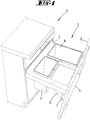
- the cabinet drawer 2 has a pull-out part 3, which is designed here as a holding frame for refuse collection container 4, and a front panel 5.
- the cabinet 1 is a conventional cabinet, as it can be used in particular as a built-in cupboard in kitchens.
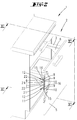
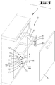
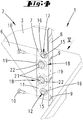
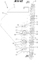
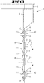
- the front panel 5 is by means of first and second fastening parts 6 and 7, see in particular Fig. 6 , connected to the extract part 3.
- the second fastening part 7 is preferably designed as a mounting bracket.
- a first fixing part 8 forming a fastening region preferably extends in the same plane E of the front plate 5.
- This fastening part 8 has one or more elongated holes 9 extending horizontally, relative to the installed state, through which fastening screws 10 in FIG Starting the front panel can be screwed by the fastening part section 8.
- fastening part section 8 has one or more elongated holes 9 extending horizontally, relative to the installed state, through which fastening screws 10 in FIG Starting the front panel can be screwed by the fastening part section 8.
- the first attachment part 6 extends vertically. It is preferably formed plate-like.
- a second fastening part section 11 extends rectified to the first fastening part 6.
- the first fastening part 6 and correspondingly also the second fastening part section 11 of the second fastening part 7 extend perpendicular to the extension plane E of the front panel 5.
- Holes 13 are formed in the second fastening part section 11 for fastening means 12, through which a fastening shaft 14 of a fastening means 12 extends.
- the fastening means 12 further has a relative to the mounting shaft 14 enlarged mounting head 15.
- the holes 13 have a larger cross-section than corresponds to the attachment shaft 14. This allows a relative mobility of the second fastening part 7 relative to the fastening means 12. Since the embodiment further also the mounting head 15 is smaller than the surface of the hole 13 corresponds, beyond a washer 16 is provided, which is a support of the head relative to the second Mounting part 7 allows.
- the fastening means 12 are in the embodiment and preferably screws which engage in holes, preferably screw holes 17 of the first fastening part 6. Relative to the first fastening part 6 are in the holes, preferably screw holes 17, inserted, preferably screwed fasteners 12 so not movable except for their insertion or screwing.
- two fastening means 12 are preferably provided, which pass through corresponding holes 13, the second fastening part 7 in the manner described. These fastening means 12 are preferably arranged spaced apart in the vertical direction. Correspondingly, the holes 13 are preferably formed vertically spaced on the second fastening part section 11 of the second fastening part 7.
- a guide member 18 is connected to the second fastening part 7, possibly rotatably connected, projecting part, which cooperates with a slot 19 in the first fastening part 6.
- the guide member 18 engages in this slot, but this is preferably not connected to the first attachment part 6.
- At least two guide members 18 are provided, which are also preferably mounted vertically below each other on the second fastening part 7.
- These two guide parts 18 preferably also interact with differently oriented oblong holes 19. As seen in the embodiment, the slots are directed across each other. A first slot 19 extends vertically and a second slot 19 horizontally.
- the guide parts 18 are formed as eccentric parts, as can be seen from the FIGS. 7 to 10 evident.
- a guide part has a handling structure 20 which is exposed to the outside in the state of attachment.
- the handling structure 20 is formed in the embodiment so that with a screwdriver, preferably a Phillips screwdriver, a rotation of the guide member 18 can be performed.
- the handling structure accordingly consists of two slots running at right angles to each other.
- a center of area M of the guide member 18 is a shaft axis S of the guide member 18 is offset, as for example from the FIGS. 8 and 10 evident.
- a Verschöspin v preferably corresponds to a tenth to a half of a diameter d of the shank 21 of the guide member 18.
- the shaft 21 may be formed as a screw shaft and, for example, cooperate for mounting with a female part. In the embodiment, however, it is provided that the shaft 21 is formed as a formed part. After assembly, which takes place at the factory so far, a transformation is made, such that a counter-holder part 22 results. As in particular from Fig.
- fastening parts 6, 7 as shown extending transversely to an extension plane E of the front panel 5, they are, in particular in the illustrated embodiment, where they extend below the extract part 3, which is here formed as a frame, for mounting and possibly later re-adjustment freely accessible.
Landscapes
- Drawers Of Furniture (AREA)
- Connection Of Plates (AREA)
- Furniture Connections (AREA)
Applications Claiming Priority (1)
| Application Number | Priority Date | Filing Date | Title |
|---|---|---|---|
| DE202011050248U DE202011050248U1 (de) | 2011-05-24 | 2011-05-24 | Schrankauszug |
Publications (1)
| Publication Number | Publication Date |
|---|---|
| EP2526820A1 true EP2526820A1 (fr) | 2012-11-28 |
Family
ID=45851390
Family Applications (1)
| Application Number | Title | Priority Date | Filing Date |
|---|---|---|---|
| EP12158970A Withdrawn EP2526820A1 (fr) | 2011-05-24 | 2012-03-12 | Tiroir d'armoire |
Country Status (2)
| Country | Link |
|---|---|
| EP (1) | EP2526820A1 (fr) |
| DE (1) | DE202011050248U1 (fr) |
Families Citing this family (5)
| Publication number | Priority date | Publication date | Assignee | Title |
|---|---|---|---|---|
| DE202011052321U1 (de) | 2011-10-19 | 2013-01-23 | Westermann Kg | Einschubrahmen |
| EP2929805B1 (fr) * | 2014-04-10 | 2016-11-23 | King Slide Works Co., Ltd. | Dispositif de réglage |
| DE202015100485U1 (de) * | 2015-02-02 | 2016-05-03 | Ninkaplast Gmbh | Bausatz für den Einbau eines Positionierungsrahmens in einen Möbelauszug |
| DE102017121385A1 (de) * | 2017-09-14 | 2019-03-14 | Paul Hettich Gmbh & Co. Kg | Blendenträger und Schubkasten |
| US10499736B2 (en) | 2018-03-29 | 2019-12-10 | Hardware Resources, Inc. | Apparatus and method for pullout cage mounting and adjustment |
Citations (10)
| Publication number | Priority date | Publication date | Assignee | Title |
|---|---|---|---|---|
| DE29702467U1 (de) | 1997-02-13 | 1997-03-27 | Blanco GmbH & Co. KG, 75038 Oberderdingen | Träger für eine Möbelfrontplatte eines möbelartigen Einrichtungsgegenstands |
| DE19606713A1 (de) * | 1996-02-23 | 1997-08-28 | Hettich Paul Gmbh & Co | Schubkasten |
| EP0757655B1 (fr) | 1994-04-25 | 1998-06-17 | Westermann Kommanditgesellschaft | Recipient collecteur d'ordures |
| EP0779230B1 (fr) | 1995-12-16 | 2000-07-26 | Westermann KG | Récipient à ordures destiné à être intégré dans un meuble |
| DE202005001283U1 (de) * | 2005-01-27 | 2005-03-31 | Hettich Paul Gmbh & Co Kg | Schubkasten mit zwei Seitenzargen und mit einer Blende |
| EP1136392B1 (fr) | 2000-03-23 | 2008-07-16 | Westermann KG | Tiroir d'un armoir, notamment d'un meuble de cuisine, pour le maintien de poubelles |
| DE202007017999U1 (de) * | 2007-12-22 | 2009-04-30 | Paul Hettich Gmbh & Co. Kg | Frontverstellung für Schubkästen und Schubkasten |
| DE202008004220U1 (de) | 2008-01-26 | 2009-06-10 | Westermann Kg | In ein Schrankmöbel eingebauter, schienenverfahrbarer Auszug |
| DE202008012170U1 (de) * | 2008-04-18 | 2009-09-03 | Paul Hettich Gmbh & Co. Kg | Verstellvorrichtung für Möbel |
| WO2011094774A1 (fr) * | 2010-02-03 | 2011-08-11 | Julius Blum Gmbh | Châssis de tiroir |
Family Cites Families (4)
| Publication number | Priority date | Publication date | Assignee | Title |
|---|---|---|---|---|
| AT304802B (de) * | 1970-11-13 | 1973-01-25 | Osta Werke Gmbh | Beschlag zum Einstellen und Fixieren der Frontplatte eines ausziehbaren Möbelteiles |
| AT328651B (de) * | 1972-06-12 | 1976-04-12 | Blum Gmbh Julius | Beschlag zum einstellen und fixieren der frontplatte eines ausziehbaren mobelteiles |
| AT385886B (de) * | 1983-07-19 | 1988-05-25 | Blum Gmbh Julius | Befestigungsvorrichtung |
| DE102004041300A1 (de) * | 2004-08-25 | 2006-03-02 | Lautenschläger, Horst | Verstelleinrichtung für Möbelteile |
-
2011
- 2011-05-24 DE DE202011050248U patent/DE202011050248U1/de not_active Expired - Lifetime
-
2012
- 2012-03-12 EP EP12158970A patent/EP2526820A1/fr not_active Withdrawn
Patent Citations (10)
| Publication number | Priority date | Publication date | Assignee | Title |
|---|---|---|---|---|
| EP0757655B1 (fr) | 1994-04-25 | 1998-06-17 | Westermann Kommanditgesellschaft | Recipient collecteur d'ordures |
| EP0779230B1 (fr) | 1995-12-16 | 2000-07-26 | Westermann KG | Récipient à ordures destiné à être intégré dans un meuble |
| DE19606713A1 (de) * | 1996-02-23 | 1997-08-28 | Hettich Paul Gmbh & Co | Schubkasten |
| DE29702467U1 (de) | 1997-02-13 | 1997-03-27 | Blanco GmbH & Co. KG, 75038 Oberderdingen | Träger für eine Möbelfrontplatte eines möbelartigen Einrichtungsgegenstands |
| EP1136392B1 (fr) | 2000-03-23 | 2008-07-16 | Westermann KG | Tiroir d'un armoir, notamment d'un meuble de cuisine, pour le maintien de poubelles |
| DE202005001283U1 (de) * | 2005-01-27 | 2005-03-31 | Hettich Paul Gmbh & Co Kg | Schubkasten mit zwei Seitenzargen und mit einer Blende |
| DE202007017999U1 (de) * | 2007-12-22 | 2009-04-30 | Paul Hettich Gmbh & Co. Kg | Frontverstellung für Schubkästen und Schubkasten |
| DE202008004220U1 (de) | 2008-01-26 | 2009-06-10 | Westermann Kg | In ein Schrankmöbel eingebauter, schienenverfahrbarer Auszug |
| DE202008012170U1 (de) * | 2008-04-18 | 2009-09-03 | Paul Hettich Gmbh & Co. Kg | Verstellvorrichtung für Möbel |
| WO2011094774A1 (fr) * | 2010-02-03 | 2011-08-11 | Julius Blum Gmbh | Châssis de tiroir |
Also Published As
| Publication number | Publication date |
|---|---|
| DE202011050248U1 (de) | 2012-08-27 |
Similar Documents
| Publication | Publication Date | Title |
|---|---|---|
| DE102013112645B3 (de) | Türband | |
| AT399087B (de) | Befestigungsbeschlag für schubladen-frontblenden | |
| EP3542672B1 (fr) | Ferrure de meuble destinée au montage du panneau avant | |
| EP2642893B1 (fr) | Raccord pour un panneau d'un tiroir | |
| DE202015103874U1 (de) | Vorrichtung zum Verbinden zweier Möbelteile | |
| EP1653031B1 (fr) | Charnière de porte pliante | |
| WO2010003749A1 (fr) | Charnière | |
| EP2526820A1 (fr) | Tiroir d'armoire | |
| EP3103948B1 (fr) | Penture pour une porte ou une fenêtre | |
| EP2309137A1 (fr) | Cheville d'un dispositif d'assemblage | |
| DE8601782U1 (de) | Befestigungsvorrichtung für verstellbare Frontplatten | |
| DE102004037548B4 (de) | Ausrichtvorrichtung und/oder Aufhängevorrichtungssystem | |
| EP2064972B1 (fr) | Tiroir d'armoire doté d'une partie de support et d'une façade de meuble pouvant être fixée dessus | |
| CH664678A5 (de) | Schubkastenauszug. | |
| EP2256443A2 (fr) | Système de porte pour un appareil de réfrigération et/ou de congélation, appareil de réfrigération et/ou de congélation et procédé destiné au montage d'un système de porte | |
| EP2208843B1 (fr) | Charnière pour une porte | |
| EP1454026B1 (fr) | Plaque de montage pour la fixation reglable de charnieres de meuble sur le corps de meubles | |
| EP2778332A2 (fr) | Équerre de fixation pour une porte coulissante | |
| EP1518482A2 (fr) | Dispositif de suspension pour un placard le long d'un mur | |
| EP2108774B1 (fr) | Charnière | |
| EP2850983B1 (fr) | Séparation de douche | |
| AT516730B1 (de) | Befestigungsvorrichtung für eine Frontblende sowie damit ausgestattetes Möbelstück | |
| DE102018130350B3 (de) | Bandlappen und Band zur um eine Scharnierachse scharniergelenkigen Verbindung eines Flügels mit einem Rahmen | |
| DE3500423A1 (de) | Scharnier, insbesondere fuer moebel | |
| DE202012012133U1 (de) | Möbel und Anbringvorrichtung für eine Möbelfront an einem Möbel |
Legal Events
| Date | Code | Title | Description |
|---|---|---|---|
| PUAI | Public reference made under article 153(3) epc to a published international application that has entered the european phase |
Free format text: ORIGINAL CODE: 0009012 |
|
| AK | Designated contracting states |
Kind code of ref document: A1 Designated state(s): AL AT BE BG CH CY CZ DE DK EE ES FI FR GB GR HR HU IE IS IT LI LT LU LV MC MK MT NL NO PL PT RO RS SE SI SK SM TR |
|
| AX | Request for extension of the european patent |
Extension state: BA ME |
|
| STAA | Information on the status of an ep patent application or granted ep patent |
Free format text: STATUS: THE APPLICATION IS DEEMED TO BE WITHDRAWN |
|
| 18D | Application deemed to be withdrawn |
Effective date: 20130529 |