EP2526854A1 - Système d'endoscope et procédé d'aide au diagnostic en endoscopie - Google Patents
Système d'endoscope et procédé d'aide au diagnostic en endoscopie Download PDFInfo
- Publication number
- EP2526854A1 EP2526854A1 EP12169077A EP12169077A EP2526854A1 EP 2526854 A1 EP2526854 A1 EP 2526854A1 EP 12169077 A EP12169077 A EP 12169077A EP 12169077 A EP12169077 A EP 12169077A EP 2526854 A1 EP2526854 A1 EP 2526854A1
- Authority
- EP
- European Patent Office
- Prior art keywords
- image
- oxygen saturation
- light
- section
- blue
- Prior art date
- Legal status (The legal status is an assumption and is not a legal conclusion. Google has not performed a legal analysis and makes no representation as to the accuracy of the status listed.)
- Granted
Links
- 238000000034 method Methods 0.000 title claims description 10
- 238000001839 endoscopy Methods 0.000 title claims description 5
- QVGXLLKOCUKJST-UHFFFAOYSA-N atomic oxygen Chemical compound [O] QVGXLLKOCUKJST-UHFFFAOYSA-N 0.000 claims abstract description 186
- 229910052760 oxygen Inorganic materials 0.000 claims abstract description 186
- 239000001301 oxygen Substances 0.000 claims abstract description 186
- 230000003902 lesion Effects 0.000 claims abstract description 48
- 210000004204 blood vessel Anatomy 0.000 claims abstract description 41
- 206010021143 Hypoxia Diseases 0.000 claims abstract description 19
- 230000001146 hypoxic effect Effects 0.000 claims abstract description 18
- 238000003384 imaging method Methods 0.000 claims description 38
- 238000005286 illumination Methods 0.000 claims description 27
- 238000012545 processing Methods 0.000 claims description 22
- 238000001514 detection method Methods 0.000 claims description 13
- 239000008280 blood Substances 0.000 claims description 10
- 210000004369 blood Anatomy 0.000 claims description 10
- 238000001914 filtration Methods 0.000 claims description 9
- 238000010521 absorption reaction Methods 0.000 claims description 5
- 206010028980 Neoplasm Diseases 0.000 description 20
- 201000011510 cancer Diseases 0.000 description 20
- 239000013307 optical fiber Substances 0.000 description 17
- OAICVXFJPJFONN-UHFFFAOYSA-N Phosphorus Chemical compound [P] OAICVXFJPJFONN-UHFFFAOYSA-N 0.000 description 12
- 238000003745 diagnosis Methods 0.000 description 10
- 238000012216 screening Methods 0.000 description 8
- 108010054147 Hemoglobins Proteins 0.000 description 5
- 102000001554 Hemoglobins Human genes 0.000 description 5
- INGWEZCOABYORO-UHFFFAOYSA-N 2-(furan-2-yl)-7-methyl-1h-1,8-naphthyridin-4-one Chemical compound N=1C2=NC(C)=CC=C2C(O)=CC=1C1=CC=CO1 INGWEZCOABYORO-UHFFFAOYSA-N 0.000 description 4
- 239000003086 colorant Substances 0.000 description 4
- 230000005284 excitation Effects 0.000 description 4
- 230000003595 spectral effect Effects 0.000 description 4
- 238000002834 transmittance Methods 0.000 description 4
- 230000002792 vascular Effects 0.000 description 4
- 238000002835 absorbance Methods 0.000 description 3
- 238000005452 bending Methods 0.000 description 3
- 238000006243 chemical reaction Methods 0.000 description 3
- 239000002131 composite material Substances 0.000 description 3
- 239000000126 substance Substances 0.000 description 3
- 108010064719 Oxyhemoglobins Proteins 0.000 description 2
- 230000002950 deficient Effects 0.000 description 2
- 108010002255 deoxyhemoglobin Proteins 0.000 description 2
- 238000010586 diagram Methods 0.000 description 2
- 239000000835 fiber Substances 0.000 description 2
- 210000001519 tissue Anatomy 0.000 description 2
- 0 CCC1=C(C)[C@](*)(C2C3=C4C5=C(C*)C(C6*C)C6(C)[C@@]5C(C)[C@@]4(C4C)C34C(C)C22)C2(C)[C@]1C Chemical compound CCC1=C(C)[C@](*)(C2C3=C4C5=C(C*)C(C6*C)C6(C)[C@@]5C(C)[C@@]4(C4C)C34C(C)C22)C2(C)[C@]1C 0.000 description 1
- 206010020880 Hypertrophy Diseases 0.000 description 1
- 206010061218 Inflammation Diseases 0.000 description 1
- 238000013459 approach Methods 0.000 description 1
- 230000000295 complement effect Effects 0.000 description 1
- 230000007423 decrease Effects 0.000 description 1
- 230000003247 decreasing effect Effects 0.000 description 1
- 238000003748 differential diagnosis Methods 0.000 description 1
- 238000000295 emission spectrum Methods 0.000 description 1
- 230000004054 inflammatory process Effects 0.000 description 1
- 239000011159 matrix material Substances 0.000 description 1
- 229910044991 metal oxide Inorganic materials 0.000 description 1
- 150000004706 metal oxides Chemical class 0.000 description 1
- 238000012986 modification Methods 0.000 description 1
- 230000004048 modification Effects 0.000 description 1
- 210000004877 mucosa Anatomy 0.000 description 1
- 230000035515 penetration Effects 0.000 description 1
- 239000004065 semiconductor Substances 0.000 description 1
- 229910052724 xenon Inorganic materials 0.000 description 1
- FHNFHKCVQCLJFQ-UHFFFAOYSA-N xenon atom Chemical compound [Xe] FHNFHKCVQCLJFQ-UHFFFAOYSA-N 0.000 description 1
Images




Classifications
-
- A—HUMAN NECESSITIES
- A61—MEDICAL OR VETERINARY SCIENCE; HYGIENE
- A61B—DIAGNOSIS; SURGERY; IDENTIFICATION
- A61B1/00—Instruments for performing medical examinations of the interior of cavities or tubes of the body by visual or photographical inspection, e.g. endoscopes; Illuminating arrangements therefor
- A61B1/00002—Operational features of endoscopes
- A61B1/00004—Operational features of endoscopes characterised by electronic signal processing
- A61B1/00009—Operational features of endoscopes characterised by electronic signal processing of image signals during a use of endoscope
- A61B1/000094—Operational features of endoscopes characterised by electronic signal processing of image signals during a use of endoscope extracting biological structures
-
- A—HUMAN NECESSITIES
- A61—MEDICAL OR VETERINARY SCIENCE; HYGIENE
- A61B—DIAGNOSIS; SURGERY; IDENTIFICATION
- A61B1/00—Instruments for performing medical examinations of the interior of cavities or tubes of the body by visual or photographical inspection, e.g. endoscopes; Illuminating arrangements therefor
- A61B1/00002—Operational features of endoscopes
- A61B1/00043—Operational features of endoscopes provided with output arrangements
- A61B1/00045—Display arrangement
- A61B1/0005—Display arrangement combining images e.g. side-by-side, superimposed or tiled
-
- A—HUMAN NECESSITIES
- A61—MEDICAL OR VETERINARY SCIENCE; HYGIENE
- A61B—DIAGNOSIS; SURGERY; IDENTIFICATION
- A61B1/00—Instruments for performing medical examinations of the interior of cavities or tubes of the body by visual or photographical inspection, e.g. endoscopes; Illuminating arrangements therefor
- A61B1/04—Instruments for performing medical examinations of the interior of cavities or tubes of the body by visual or photographical inspection, e.g. endoscopes; Illuminating arrangements therefor combined with photographic or television appliances
- A61B1/044—Instruments for performing medical examinations of the interior of cavities or tubes of the body by visual or photographical inspection, e.g. endoscopes; Illuminating arrangements therefor combined with photographic or television appliances for absorption imaging
-
- A—HUMAN NECESSITIES
- A61—MEDICAL OR VETERINARY SCIENCE; HYGIENE
- A61B—DIAGNOSIS; SURGERY; IDENTIFICATION
- A61B1/00—Instruments for performing medical examinations of the interior of cavities or tubes of the body by visual or photographical inspection, e.g. endoscopes; Illuminating arrangements therefor
- A61B1/06—Instruments for performing medical examinations of the interior of cavities or tubes of the body by visual or photographical inspection, e.g. endoscopes; Illuminating arrangements therefor with illuminating arrangements
- A61B1/063—Instruments for performing medical examinations of the interior of cavities or tubes of the body by visual or photographical inspection, e.g. endoscopes; Illuminating arrangements therefor with illuminating arrangements for monochromatic or narrow-band illumination
-
- A—HUMAN NECESSITIES
- A61—MEDICAL OR VETERINARY SCIENCE; HYGIENE
- A61B—DIAGNOSIS; SURGERY; IDENTIFICATION
- A61B1/00—Instruments for performing medical examinations of the interior of cavities or tubes of the body by visual or photographical inspection, e.g. endoscopes; Illuminating arrangements therefor
- A61B1/06—Instruments for performing medical examinations of the interior of cavities or tubes of the body by visual or photographical inspection, e.g. endoscopes; Illuminating arrangements therefor with illuminating arrangements
- A61B1/0638—Instruments for performing medical examinations of the interior of cavities or tubes of the body by visual or photographical inspection, e.g. endoscopes; Illuminating arrangements therefor with illuminating arrangements providing two or more wavelengths
-
- A—HUMAN NECESSITIES
- A61—MEDICAL OR VETERINARY SCIENCE; HYGIENE
- A61B—DIAGNOSIS; SURGERY; IDENTIFICATION
- A61B1/00—Instruments for performing medical examinations of the interior of cavities or tubes of the body by visual or photographical inspection, e.g. endoscopes; Illuminating arrangements therefor
- A61B1/06—Instruments for performing medical examinations of the interior of cavities or tubes of the body by visual or photographical inspection, e.g. endoscopes; Illuminating arrangements therefor with illuminating arrangements
- A61B1/0661—Endoscope light sources
- A61B1/0669—Endoscope light sources at proximal end of an endoscope
-
- A—HUMAN NECESSITIES
- A61—MEDICAL OR VETERINARY SCIENCE; HYGIENE
- A61B—DIAGNOSIS; SURGERY; IDENTIFICATION
- A61B5/00—Measuring for diagnostic purposes; Identification of persons
- A61B5/0059—Measuring for diagnostic purposes; Identification of persons using light, e.g. diagnosis by transillumination, diascopy, fluorescence
- A61B5/0082—Measuring for diagnostic purposes; Identification of persons using light, e.g. diagnosis by transillumination, diascopy, fluorescence adapted for particular medical purposes
- A61B5/0084—Measuring for diagnostic purposes; Identification of persons using light, e.g. diagnosis by transillumination, diascopy, fluorescence adapted for particular medical purposes for introduction into the body, e.g. by catheters
-
- A—HUMAN NECESSITIES
- A61—MEDICAL OR VETERINARY SCIENCE; HYGIENE
- A61B—DIAGNOSIS; SURGERY; IDENTIFICATION
- A61B5/00—Measuring for diagnostic purposes; Identification of persons
- A61B5/74—Details of notification to user or communication with user or patient; User input means
- A61B5/742—Details of notification to user or communication with user or patient; User input means using visual displays
- A61B5/7425—Displaying combinations of multiple images regardless of image source, e.g. displaying a reference anatomical image with a live image
-
- A—HUMAN NECESSITIES
- A61—MEDICAL OR VETERINARY SCIENCE; HYGIENE
- A61B—DIAGNOSIS; SURGERY; IDENTIFICATION
- A61B1/00—Instruments for performing medical examinations of the interior of cavities or tubes of the body by visual or photographical inspection, e.g. endoscopes; Illuminating arrangements therefor
- A61B1/06—Instruments for performing medical examinations of the interior of cavities or tubes of the body by visual or photographical inspection, e.g. endoscopes; Illuminating arrangements therefor with illuminating arrangements
- A61B1/0653—Instruments for performing medical examinations of the interior of cavities or tubes of the body by visual or photographical inspection, e.g. endoscopes; Illuminating arrangements therefor with illuminating arrangements with wavelength conversion
Definitions
- the present invention relates to an endoscope system for automatically detecting a lesion, for example, cancer, and a method for assisting in diagnostic endoscopy.
- Cancer diagnoses using endoscopes have been common in the medical field.
- a cancer diagnosis using an endoscope first, screening for detecting a cancer-suspected lesion is performed when a region of interest is in a far view. Then, the endoscope approaches the cancer-suspected lesion such that the lesion is in a near view. In this state, detailed diagnosis is performed to determine whether the suspected lesion is actually cancer.
- hypertrophy cancer that is cancer increased in size can be easily distinguished under normal observation using white light. However, it is difficult to distinguish the cancer when it resembles inflammation or is embedded in surrounding tissue.
- An object of the present invention is to provide an endoscope system and a method for assisting in diagnostic endoscopy for measuring an oxygen saturation level of a cancer-suspected lesion at the time of screening so as to avoid detection of a false positive area and perform cancer diagnosis efficiently.
- the endoscope system of the present invention includes a lighting section, an imaging section, an image processor, a suspected-lesion detection section, an oxygen saturation calculation section, a judging section, and a display section.
- the lighting section applies illumination light, selected from two or more types of illumination light, to a region of interest.
- the imaging section images the region of interest illuminated with the illumination light selected.
- the image processor produces an observation image based on an image signal acquired from the imaging section.
- the observation image corresponds to the illumination light selected.
- the suspected-lesion detection section detects a suspected lesion in the observation image.
- the oxygen saturation calculation section obtains an oxygen saturation level of a blood vessel in the observation image.
- the judging section judges whether the oxygen saturation level in the suspected lesion is in a hypoxic condition within a predetermined range.
- the display section displays the observation image.
- the lighting section selectively generates one of white light, mixed light in which the white light is mixed with blue narrowband light at a predetermined ratio, and two or more types of narrowband light each having an absorption coefficient varying with the oxygen saturation level, as the illumination light.
- the image processor includes a special image processing section for combining a normal light image with a blue-enhanced image to produce a special image in which the blood vessel is enhanced.
- the normal light image is produced based on the image signal outputted from the imaging section during illumination with the white light.
- the blue-enhanced image is produced based on the image signal outputted from the imaging section during illumination with the mixed light.
- the lighting section alternately generates the white light and the mixed light in respective frames.
- the imaging section alternately outputs the image signal of the normal light image of one frame and the image signal of the blue-enhanced image of one frame.
- the special image processing section performs frequency filtering of a bandwidth ranging from a low frequency to a high frequency to the blue-enhanced image before combining the normal light image with the blue-enhanced image.
- the oxygen saturation calculating section acquires two or more oxygen saturation signals from the image signals outputted from the imaging section during the sequential illumination with the respective narrowband light.
- the image signals correspond to the respective narrowband light.
- the oxygen saturation level is obtained from magnitude of a ratio between the oxygen saturation signals.
- the image processor further includes an oxygen saturation image processing section for producing an oxygen saturation image that is an image of the blood vessel represented by the oxygen saturation level.
- the blood vessel in the oxygen saturation image is colored in accordance with the oxygen saturation level.
- the endoscope system further includes a display controller for allowing the display section to display the special image before the suspected lesion is detected, and to display the oxygen saturation image when the suspected lesion is judged to be in the hypoxic condition.
- the display controller allows the display section to temporarily display the oxygen saturation image between after the suspected lesion is detected and before the suspected lesion is judged to be in the hypoxic condition.
- the display controller displays a message on the display section.
- the message notifies that the oxygen saturation image will be displayed on the display section.
- the method for assisting in diagnostic endoscopy includes an white light applying step, a normal light image producing step, a mixed light applying step, a blue-enhanced image producing step, a combining step, a detecting step, a narrowband light applying step, a signal acquiring step, an oxygen saturation level obtaining step, an oxygen saturation image producing step, a judging step, and a displaying step.
- white light applying step white light is applied to a region of interest in a body cavity.
- the normal light image producing step a normal light image is produced based on an image signal outputted from the imaging section during illumination with the white light.
- the mixed light applying step mixed light of the white light and blue narrowband light is applied to the region of interest.
- the white light and the blue narrowband light is mixed at a predetermined ratio.
- the blue-enhanced image producing step the blue-enhanced image is produced based on an image signal outputted from the imaging section during illumination with the mixed light.
- the normal light image is combined with the blue-enhanced image to produce a special image in which a blood vessel is enhanced.
- a suspected lesion is detected in the special image.
- the narrowband light applying step two or more types of narrowband light is applied sequentially to the region of interest. An absorption coefficient of each narrowband light varies with an oxygen saturation level.
- the signal acquiring step two or more oxygen saturation signals are acquired from image signals, corresponding to the respective narrowband light, outputted from the imaging section during the sequential illumination with the narrowband light.
- an oxygen saturation level of blood in the blood vessel is obtained from magnitude of a ratio between the oxygen saturation signals.
- an oxygen saturation image that is an image of the blood vessel represented by the oxygen saturation level is produced.
- the judging step it is judged whether the oxygen saturation level of the suspected lesion is in the hypoxic condition within a predetermined range.
- the special image is displayed on a display section before the suspected lesion is detected, and the oxygen saturation image is displayed on the display section when the suspected lesion is judged to be in the hypoxic condition.
- the oxygen saturation image is temporarily displayed on the display section between after the suspected lesion is detected and before the suspected lesion is judged to be in the hypoxic condition.
- a suspected lesion such as cancer is picked up based on whether the suspected lesion is in the hypoxic condition. This avoids the detection of the false positive area and thus the cancer diagnosis is performed efficiently.
- the special image used for detecting the suspected lesion is produced by combining the overall bright normal light image with the blue-enhanced image in which the blood vessels and their structure are enhanced. Accordingly, the suspected lesion is surely detected even if the light quantity is deficient, for example, when the region of interest is in a far view.
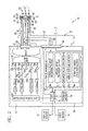
- an endoscope system 10 is provided with a light source device 11, an endoscope device 12, a processor device 13, a display device 14, and an input device 15.
- the light source device 11 generates illumination light.
- the endoscope device 12 guides the illumination light from the light source device 11 and applies the illumination light to a region of interest in a body cavity (subject).
- the endoscope device 12 images the region of interest illuminated with the illumination light and acquires an image signal.
- the processor device 13 performs image processing to the image signal.
- the display device 14 displays an endoscopic image produced by the image processing.
- the input device 15 includes a keyboard, for example.
- the endoscope system 10 is provided with three modes: a normal observation mode, a first special observation mode, and a second special observation mode.
- the display device 14 displays a normal light image represented by visible light in a wavelength range from blue to red.
- the first special observation mode a content of a display image is switched between a far view and a near view.
- the far view refers to a long observation distance (see Fig. 14 ) between a region of interest "R" of the subject and a distal portion 40 of the endoscope device 12.
- the near view refers to a short observation distance between the region of interest "R" and the distal portion 40.
- a suspected lesion for example, a spot or a brownish area is detected.
- the first special observation mode is further classified into “1-1" to "1-5" special observation modes depending on a content of image (s) displayed on the display device 14 when the region of interest is in the near view.
- a selection switch 17 provided on the endoscope device 12 is used for switching between the observation modes.
- the light source device 11 is provided with four types of lasers LD1, LD2, LD3, and LD4, a light source controller 20, a combiner 21, and a splitter 22.
- the laser LD1 generates first narrowband light N1 having a center wavelength of 405 nm.
- the laser LD2 generates second narrowband light N2 having a center wavelength of 445 nm.
- the laser LD3 generates third narrowband light N3 having a center wavelength of 473 nm.
- the laser LD4 generates fourth narrowband light N4 having a center wavelength of 650 nm.
- the second narrowband light N2 is used for exciting a phosphor 50, disposed in the distal portion 40 of the endoscope device 12, to produce white light (pseudo white light).
- the first to fourth narrowband light N1 to N4 is used for calculation of an oxygen saturation level of hemoglobin in blood.
- a broad area type InGaN laser diode, an InGaNAs laser diode, a GaNAs laser diode or the like can be used for the lasers LD1, and LD2.
- the first narrowband light N1 is incident on a first optical fiber 24a through a condenser lens 23a.
- the third narrowband light N3 is incident on a third optical fiber 24d through a condenser lens 23d.
- the fourth narrowband light N4 is incident on a fourth optical fiber 24e through a condenser lens 23e.
- the second narrowband light N2 is used for exciting the phosphor 50 to produce the white light
- the second narrowband light N2 is incident on a "2-1" optical fiber 24b through a condenser lens 23b.
- the second narrowband light N2 is used for calculation of the oxygen saturation level
- the second narrowband light N2 is incident on a "2-2" optical fiber 24c through light path switching mirrors 25a and 25b and a condenser lens 23c.
- the light path switching mirror 25a is provided between the laser LD2 and the "2-1" optical fiber 24b.
- the light path switching mirror 25a is provided with a shift mechanism 30.
- the shift mechanism 30 shifts or moves the light path switching mirror 25a between a retracted position and an inserted position. In the retracted position, the light path switching mirror 25a is retracted from a light path of the laser LD2. In the inserted position, the light path switching mirror 25a is inserted into the light path of the laser LD2 to reflect the second narrowband light N2 to the light path switching mirror 25b.
- a controller 72 of the processor device 13 controls the shift mechanism 30.
- the light path switching mirror 25b reflects the second narrowband light N2, incident from the light path switching mirror 25a, to the condenser lens 23c.
- the light source controller 20 controls the lasers LD1 to LD4 to adjust emission timing of each laser and a light quantity ratio between the lasers.
- the emission timing and the light quantity ratio vary between the observation modes.
- the combiner 21 mixes the light from the optical fibers 24a to 24e. Then, the splitter 22, being a light distributor, splits the mixed light into four paths of light.
- light guides 26 and 27 for special light transmit the light from the first, "2-2", third, and fourth optical fibers 24a, 24c, 24d, and 24e.
- Light guides 28 and 29 for normal light transmit the light from the "2-1" optical fiber 24b.
- Each of the light guides 26 to 29 is constituted of a bundle fiber that is a plurality of fibers bundled together. The light from the lasers LD1 to LD4 may be incident on the respective light guides directly without using the combiner 21 and the splitter 22.
- the endoscope device 12 is composed of an electronic endoscope and is provided with a scope 32, a lighting section 33, an imaging section 34, a handling section 35, and a connector section 36.
- the lighting section 33 applies the four paths of light transmitted through the respective light guides 26 to 29 to the region of interest.
- the imaging section 34 images the region of interest.
- the handling section 35 is used for steering the distal portion 40 of the scope 32 and operation for the observation.
- the connector section 36 connects the scope 32, the light source device 11, and the processor device 13 in a detachable manner.
- the scope 32 is provided with a flexible tube 38, a bending portion 39, and the distal portion 40 in this order from the handling section 35 side.
- the flexible tube 38 is flexible inside the subject.
- the bending portion 39 is steered by rotating an angle knob 35a disposed in the handling section 35.
- the bending portion 39 can be bent at any angle in any direction to direct the distal portion 40 to the region of interest.
- the distal portion 40 is provided with the lighting section 33 and the imaging section 34.
- the imaging section 34 is provided with a capture window 42 substantially at the center of an end face of the distal portion 40. The light reflected from the region of interest is incident on the capture window 42.
- the lighting section 33 includes two lighting windows 43 and 44 provided on respective sides of the imaging section 34.
- Two projection units 46 and 47 are disposed behind the lighting window 43.
- the projection unit 46 projects the first to fourth narrowband light N1 to N4 from the light guide 26 to the region of interest through a lens 48.
- the projection unit 47 applies the second narrowband light N2 from the light guide 28 to the phosphor 50 to produce the white light.
- the white light is projected to the region of interest through a lens 51.
- Projection units 53 and 54 are disposed behind the lighting window 44 in a manner similar to the lighting window 43.
- the projection unit 53 projects the first to fourth narrowband light N1 to N4 from the light guide 27 to the region of interest through the lens 48.
- the projection unit 54 applies the second narrowband light N2 from the light guide 29 to the phosphor 50 to project the white light to the region of interest through the lens 51.
- the capture window 42 is disposed between the lighting windows 43 and 44.
- the four projection units 46, 47, 53, and 54 are arranged such that an alternate long and short dash line L1 between the output surfaces of the projection units 47 and 54 and an alternate long and short dash line L2 between the output surfaces of the projection units 46 and 53 cross each other at a center portion of the capture window 42. This arrangement prevents unevenness in lighting.
- Each of the projection units 47 and 54 projects the white light.
- Each of the projection units 46 and 53 projects the first to fourth narrowband light N1 to N4.
- the phosphor 50 includes several kinds of fluorescent substances, for example, YAG fluorescent substances or BAM(BaMgAl 10 O 17 ). These fluorescent substances absorb a part of the second narrowband light N2 to emit green to yellow light (fluorescence). The green to yellow light emitted from the phosphor 50 is mixed with the second narrowband light N2, passed through the phosphor 50 without being absorbed, to produce the white light (pseudo white light).
- a commercially available product under the product name Micro White (or MW) (registered trademark) may be used as the phosphor 50.
- the white light of the present invention does not necessarily include all wavelength components of the visible light. Like the above-described pseudo white light, the white light only needs to include light in a specific wavelength range such as light of a primary color (red, green, or blue), for example. In other words, the white light may be light having wavelength components from green to red or light having wavelength components from blue to green, for example.
- a primary color red, green, or blue
- an objective lens unit (not shown) is provided behind the capture window 42.
- the objective lens unit captures light (image light) reflected from the region of interest of the subject.
- An image sensor 60 is provided behind the objective lens unit.
- the image sensor 60 is a CCD (Charge Coupled Device) or a CMOS (Complementary Metal-Oxide Semiconductor), for example.
- the image sensor 60 receives the image light of the region of interest to produce an image thereof.
- the image sensor 60 is controlled by an imaging controller 70.
- a light receiving surface (imaging surface) of the image sensor 60 receives the light from the objective lens unit.
- the image sensor 60 is a color CCD.
- On the light receiving surface of the image sensor 60 a pixel group composed of a plurality of pixel sets, each having an R (red) pixel, a G (green) pixel, and a B (blue) pixel, is arranged in a matrix of a predetermined pattern.
- Each B pixel has spectral transmittance 63, and each G pixel has spectral transmittance 64, and each R pixel has spectral transmittance 65 as shown in Fig. 5 .
- the light received by each pixel in the image sensor 60 is photoelectrically converted into electric charge and stored. The electric charge is stored for a predetermined time. Thereafter, the electric charge stored in each pixel is read out, and the charge read-out is outputted as an image signal (analog signal) of one frame.
- the image signal outputted from the image sensor 60 is inputted to an A/D converter 68 through a scope cable 67.
- the A/D converter 68 converts the analog image signal into a digital image signal in accordance with voltage of the analog image signal.
- the digital image signal includes a blue signal, a green signal, and a red signal.
- the blue signal is acquired by the A/D conversion of a pixel signal outputted from the B pixel.
- the green signal is acquired by the A/D conversion of a pixel signal outputted from the G pixel.
- the red signal is acquired by the A/D conversion of a pixel signal outputted from the R signal.
- the digital image signal is inputted to an image processor 73 of the processor device 13 through the connector section 36.
- the channels include, for example, an air/water channel and a forceps channel through which a sample collecting device or the like is inserted.
- the processor device 13 is provided with the controller 72, the image processor 73, and a storage section 74.
- the controller 72 is connected to the display device 14 and the input device 15.
- the controller 72 controls operations of the image processor 73, the light source controller 20 and the shift mechanism 30 of the light source device 11, the imaging controller 70 of the endoscope device 12, and the display device 14, according to a switching signal from the selection switch 17 of the endoscope device 12, an input signal from the input device 15, or a result of processing of the image processor 73.
- the image processor 73 is provided with a normal light image processing section 80, a special image processing section 81, a distance calculating section 82, a display switching section 83, and a suspected-lesion detection section 84.
- the normal light image processing section 80 produces the color normal light image based on the normal light image signal.
- the normal light image signal is acquired by imaging the region of interest illuminated with the white light.
- the laser LD2 is turned on while the lasers LD1, LD3, and LD4 are turned off.
- the second narrowband light N2 from the laser LD2 is incident on the "2-1" optical fiber 24b.
- the image sensor 60 photoelectrically converts the reflection light from the region of interest.
- the normal light image signal is acquired.
- the normal light image signal is acquired on a frame-by-frame basis.
- the special image processing section 81 is provided with a first special image producing section 90, a second special image producing section 91, and an oxygen saturation image processing section 92.
- the first special image producing section 90 produces a first special image that is a composite image of the normal light image with the superficial blood vessels enhanced.
- the second special image producing section 91 produces a second special image in which the superficial blood vessels and the middle and deep blood vessels are enhanced.
- the oxygen saturation image processing section 92 calculates the oxygen saturation level of hemoglobin in blood and produces an oxygen saturation image to which colors are assigned in accordance with the oxygen saturation levels calculated. Note that the normal light image is not used as the second special image.
- the first special image producing section 90 produces the normal light image (imaged with the illumination of the white light) based on the normal light image signal.
- the first special image producing section 90 also produces a first blue-enhanced image based on a first blue-enhanced image signal.
- the first blue-enhanced image signal is acquired by imaging the region of interest illuminated with the white light and the first narrowband light N1 in the blue region.
- the first blue-enhanced image is subjected to frequency filtering of a predetermined bandwidth. Thereby, the blood vessels and their shapes are enhanced in the image.
- the first blue-enhanced image may be subjected to color processing to display the blood vessels and mucosa in different colors and image structure processing such as sharpness enhancement and edge enhancement.
- broadband frequency filtering (ranging from low frequency to high frequency, see Fig. 8A ) is performed to enhance superficial blood vessels and a superficial microstructure such as a spot and a brownish area.
- the spot refers to a lump in which blood vessels are densely crowded.
- the brownish area refers to a brown-colored area in which superficial capillary vessels are densely crowded to form a lump.
- narrowband frequency filtering (at around middle frequency, see Fig. 8B ) is performed to enhance broad blood vessels located deeper than the superficial layer and the shapes of the broad blood vessels.
- a first special image is produced by combining the normal light image with the first blue-enhanced image subjected to the frequency filtering.
- the shapes of the superficial blood vessels are enhanced in the first special image.
- To combine the normal light image with the first blue-enhanced image it is preferable to combine the normal light image with a B image produced based on a blue signal of the first blue-enhanced image and a G image produced based on a green signal of the first blue-enhanced image.
- the first blue-enhanced image with the blood vessels and their shapes enhanced is added to the normal light image with overall brightness.
- the normal light image signal and the first blue-enhanced image signal are acquired from the normal light image signal acquisition frame and the first blue-enhanced image signal acquisition frame, respectively. Namely, the image signals of two frames are acquired.
- the normal light image signal acquisition frame only the laser LD2 is turned on as described above.
- the lasers LD1 and LD2 are turned on while the lasers LD3 and LD4 are turned off. Thereby, the first and second narrowband light N1 and N2 is applied to the region of interest.
- the first narrowband light N1 from the laser LD1 is applied directly to the region of interest through the first optical fiber 24a.
- the second narrowband light N2 from the laser LD2 is incident on the "2-1" optical fiber 24b.
- the second narrowband light N2 from the "2-1" optical fiber 24b is incident on the phosphor 50 to produce the white light by the excitation.
- the white light is applied to the region of interest.
- the image sensor 60 images the region of interest illuminated with the first narrowband light N1 and the white light.
- the first blue-enhanced image signal is acquired.
- the normal light image signal and the first blue-enhanced image signal are alternately acquired from the respective frames.
- the quantity of the second narrowband light N2 (445 nm) is set greater than that of the first narrowband light N1 (405 nm), namely, the quantity of the second narrowband light N2 (445 nm) > the quantity of the first narrowband light N1(405 nm).
- the ratio of the white light is greater than that of the first narrowband light N1.
- the second special image producing section 91 produces a second special image based on a second blue-enhanced image signal acquired by imaging the subject illuminated with the white light and the first narrowband light N1 in the blue region.
- the second blue-enhanced image signal used for producing a second blue-enhanced image, is acquired from a second blue-enhanced image signal acquisition frame.
- the first narrowband light N1 and the white light is applied to the subject.
- the light quantity of the first narrowband light N1 is set greater than that of the second narrowband light N2, namely, the quantity of first narrowband light N1 (405 nm) > the quantity of the second narrowband light N2 (445 nm).
- the second blue-enhanced image signal is acquired.
- a blue signal of the second blue-enhanced image signal is assigned to a B channel and a G channel of a display signal.
- a green signal of the second blue-enhanced image signal is assigned to an R channel of the display signal.
- the second special image is substantially the same as an image produced using NBI (narrowband imaging) in which the blue narrowband signal having a blue narrowband component of 415 nm is assigned to B and G channels of the display signal and a green narrowband signal having a green narrowband component of 540 nm is assigned to the R channel of the display signal.
- NBI narrowband imaging
- the oxygen saturation image processing section 92 is provided with an oxygen saturation level calculation section 92a, an oxygen saturation image producing section 92b, and a third special image producing section 92c.
- the oxygen saturation level calculation section 92a calculates the oxygen saturation level of hemoglobin in blood.
- the oxygen saturation image producing section 92b produces the oxygen saturation image based on the oxygen saturation level calculated.
- the third special image producing section 92c produces a third special image. To be more specific, the third special image is produced by reflecting information of the oxygen saturation level in the first special image.
- the oxygen saturation level calculating section 92a uses a first oxygen saturation signal S1, a second oxygen saturation signal S2, and a third oxygen saturation signal S3 to obtain or calculate the oxygen saturation level of the blood vessel in the superficial to middle and deep layer.
- the imaging using the first narrowband light N1 provides the first oxygen saturation signal S1.
- the imaging using the second narrowband light N2 provides the second oxygen saturation signal S2.
- the imaging using the third narrowband light N3 provides the third oxygen saturation signal S3.
- a fourth oxygen saturation signal S4 is used to obtain the oxygen saturation level of the blood vessel in the middle and deep layer.
- the imaging using the fourth narrowband light N4 provides the fourth oxygen saturation signal S4.
- the signal ratio S2/S1 between the second oxygen saturation signal S2 and the first oxygen saturation signal S1 and the signal ratio S3/S1 between the third oxygen saturation signal S3 and the first oxygen saturation signal S1 are obtained.
- the oxygen saturation level in each pixel is obtained using the correlation among the signal ratios S2/S1 and S3/S1, the vascular depth and the oxygen saturation level.
- the correlation is obtained from the past diagnoses or the like and stored in the storage section 74 in advance. For example, as shown in Fig. 11 , when the signal ratios are S2*/S1* and S3*/S1*, the oxygen saturation level corresponding to the signal ratios is "X(%)".
- the signal "S2" (obtained from the light at the 445 nm wavelength range) of the signal ratio S2/S1 and the signal “S3" (obtained from the light at the 473 nm wavelength range) of the signal ratio S3/S1 are those obtained from the light in a wavelength range in which oxyhemoglobin (HbO 2 ) and deoxyhemoglobin (Hb) are different in absorbance. Accordingly, the absorbance varies with the oxygen saturation level in blood, which in result changes the signal values. In other words, the signal ratios S2/S1 and S3/S1 include information of the oxygen saturation level.
- the signal “S2" obtained from the light at the 445 nm wavelength range
- the signal “S3” obtained from the light at the 473 nm wavelength range
- the signal ratios S2/S1 and S3/S1 include information of vascular depth in addition to the information of the oxygen saturation level.
- the signal ratios S2/S1 and S3/S1 themselves may not represent the information of the oxygen saturation level accurately.
- the accurate information of the oxygen saturation level is obtained by separating the information of the oxygen saturation level from the information of the vascular depth, and extracting only the information of the oxygen saturation level.
- the signal ratio S3/S1 between the third oxygen saturation signal S3 and the first oxygen saturation signal S1 and the signal ratio S4/S1 between the fourth oxygen saturation signal S4 and the first oxygen saturation signal S1 are obtained in a manner similar to the above.
- the oxygen saturation level in each pixel is obtained.
- the first to fourth oxygen saturation signals are obtained from four frames, that is, first to fourth oxygen saturation signal acquisition frames, respectively.
- the laser LD1 is turned on while the lasers LD2, LD3, and LD4 are turned off.
- the first narrowband light N1 from the laser LD1 is incident on the first optical fiber 24a.
- the first narrowband light N1 is applied to the region of interest, which is imaged by the image sensor 60. Thereby, the first oxygen saturation signal is acquired.
- the laser LD2 is turned on while the lasers LD1, LD3, and LD4 are turned off.
- the second narrowband light N2 from the laser LD2 is applied to the region of interest through the "2-2" optical fiber 24c.
- the image sensor 60 images the region of interest illuminated with the second narrowband light N2.
- the second oxygen saturation signal is acquired.
- a third oxygen saturation signal acquisition frame only the laser LD3 is turned on.
- the third narrowband light N3 from the laser LD3 is applied to the region of interest through the third optical fiber 24d.
- the image sensor 60 images the region of interest illuminated with the third narrowband light N3. Thereby, the third oxygen saturation signal is acquired.
- the fourth oxygen saturation signal acquisition frame only the laser LD4 is turned on.
- the fourth narrowband light N4 from the laser LD4 is applied to the region of interest through the fourth optical fiber 24e.
- the image sensor 60 images the region of interest illuminated with the fourth narrowband light N4. Thereby, the fourth oxygen saturation signal is acquired.
- the oxygen saturation image producing section 92b produces an oxygen saturation image, that is, an image of the oxygen saturation level(s) of blood vessel(s), strictly speaking, the oxygen saturation level(s) of blood in blood vessel(s), calculated by the oxygen saturation level calculating section 92a.
- an oxygen saturation image that is, an image of the oxygen saturation level(s) of blood vessel(s), strictly speaking, the oxygen saturation level(s) of blood in blood vessel(s), calculated by the oxygen saturation level calculating section 92a.
- the oxygen saturation image producing section 92b assigns different colors to the blood vessels in the image according to their oxygen saturation levels.
- the oxygen saturation image producing section 92b may produce a monochrome image in which the oxygen saturation levels are depicted in various shades.
- the oxygen saturation level calculated by the oxygen saturation level calculating section 92a, is reflected in the first special image in which the shapes of the superficial blood vessels are enhanced.
- the third special image is produced.
- the oxygen saturation level of an area exceeds a predetermined range (for example, when the predetermined range is 0% to 60% and the oxygen saturation level exceeds 60%)
- the information of the oxygen saturation level is not reflected in the first special image.
- the oxygen saturation level of an area is in a hypoxic condition or a state of oxygen deficiency within the predetermined range, the information of the oxygen saturation level is reflected in the first special image such that the image is depicted in pseudo colors, for example.
- the third special image offers information of the surface condition, for example, projections and depressions on the surface of the region of interest shown in the normal light image, in addition to the oxygen saturation levels of the blood vessels. This improves the diagnostic performance.
- the lower limit of the above-described predetermined range is "0%" by way of example. The lower limit may be greater than "0%"
- the oxygen saturation image in the oxygen saturation image producing section 92b or when the oxygen saturation level (the oxygen saturation image) is reflected in the first special image in the third special image producing section 92c it is preferable to produce the oxygen saturation image from an average of the oxygen saturation level calculated using the first to third oxygen saturation signals S1 to S3 and the oxygen saturation level calculated using the first, third, and fourth oxygen saturation signals S1, S3, and S4, or one of the oxygen saturation levels.
- the distance calculating section 82 calculates or obtains an observation distance (see Fig. 14 ) between the distal portion 40 and the region of interest "R" based on the images produced in the normal light image processing section 80 and the special image processing section 81.
- the distance calculating section 82 calculates or obtains an average luminance value based on the images.
- the observation distance is determined based on the average luminance value. The greater the average luminance value, the shorter the observation distance. For example, when the average luminance value is high, it is considered that the distal portion 40 is close to the region of interest R, so that the quantity of light returning to the distal portion 40 increases. Accordingly, it is judged that the region of interest R is in the near view.
- an appropriate exposure amount is automatically set in accordance with the luminance value or the like. Generally, when the region of interest R is in the near view and the light quantity is high, the exposure amount is set low. On the contrary, when the region of interest R is in the far view and the light quantity is lower than the appropriate value, the exposure amount is set high.
- the observation distance is estimated or determined based on the exposure amount.
- the display switching section 83 switches the content of the display image (s) based on the observation distance.
- a first special image 100 is displayed on the display device 14 when the region of interest R is in the far view.
- the first special image 100 is the composite image of the normal light image with the surface blood vessels enhanced. Thereby, the screening of the region of interest in the far view surely detects suspected lesions such as the spots and the brownish areas.
- an oxygen saturation image 101 is displayed in addition to the first special image 100 on the display device 14. The use of the oxygen saturation image 101 improves accuracy in distinguishing the cancer from other lesions in differential diagnosis of cancer performed when the region of interest is in the near view.
- the first special image 100 is displayed on the display device 14 when the region of interest R is in the far view.
- the observation distance calculated by the distance calculating section 82 is less than the predetermined value, namely, when the region of interest R is in the near view, only the oxygen saturation image 101 is displayed instead of the first special image 100 on the display device 14.
- the first special image 100 is displayed on the display device 14 when the region of interest R is in the far view.
- the observation distance calculated by the distance calculating section 82 is less than the predetermined value, namely, when the region of interest R is in the near view, two types of images, a second special image 102 and the oxygen saturation image 101 are displayed instead of the first special image 100 on the display device 14.
- the second special image 102 is substantially the same as the narrowband light image produced from the blue narrowband light with the center wavelength of 415 nm and the green narrowband light with the center wavelength of 540 nm.
- a pattern (structure) of the blood vessel(s) and the shape of the uneven surface (for example, the projections and depressions) are apparent in the second special image 102.
- the oxygen condition (the oxygen saturation level) of hemoglobin in blood is apparent in the oxygen saturation image 101. Accordingly, by using the two types of images, the second special image 102 and the oxygen saturation image 101, in the diagnosis, the cancer is surely distinguished from other lesions. Note that, in displaying the second special image 102 and the oxygen saturation image 101, it is preferable to set the update timing of the oxygen saturation image 101 faster than that of the second special image 102 to give priority to moving picture performance of the oxygen saturation image 101.
- the first special image 100 is displayed on the display device 14 when the region of interest R is in the far view.
- a third special image 103 is displayed instead of the first special image 100 on the display device 14.
- the third special image 103 is the composite image of the first special image in which the information of the oxygen saturation level is reflected.
- the first special image 100 is displayed on the display device 14 when the region of interest R is in the far view.
- a message (“automatically switch to the oxygen saturation image when approaching closer to the region of interest R") 14a is displayed on the display device 14.
- the oxygen saturation image 101 is displayed in addition to the first special image 100 on the display device 14 in a manner similar to the "1-1" observation mode. Note that when the region of interest R is in the near view, the image(s) of the region of interest in the near view displayed in the "1-2" to "1-5" special observation modes may be displayed on the display device 14.
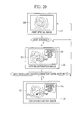
- the suspected-lesion detection section 84 detects the suspected lesion in the far view.
- the first special image 100 is obtained and displayed on the display device 14.
- the suspected-lesion detection section 84 detects a spot SP, being one type of the suspected lesions, at regular intervals.
- the spot SP is detected using image processing, for example, pattern matching.
- the suspected-lesion detection section 84 detects a spot SP larger than predetermined size or two or more spots SP each smaller than the predetermined size, the oxygen saturation image 101 is obtained temporarily. Then, the suspected-lesion detection section 84 detects whether the oxygen saturation level of each spot SP in the oxygen saturation image 101 is in the hypoxic condition within a predetermined range. During the detection, the temporarily obtained oxygen saturation level (the oxygen saturation image 101) is displayed on the display device 14, together with a message 14b notifying that the display is currently switched to the oxygen saturation image temporarily.
- the display device 14 keeps displaying the oxygen saturation image 101 together with a message 14c notifying that the display image is completely switched to the oxygen saturation image.
- the oxygen saturation level is calculated using the first to fourth oxygen saturation signals. It is also possible to calculate the oxygen saturation level using two types of signals: the third oxygen saturation signal acquired by imaging the region of interest illuminated with the third narrowband light N3 (with the center wavelength of 473 nm) and the normal light image signal. Note that the third oxygen saturation signal and the normal light image signal are acquired from the respective different frames.
- a signal ratio B1/G2 that is, a signal ratio between the blue signal B1 of the third oxygen saturation signal and the green signal G2 of the normal light image signal
- a signal ratio R2/G2 that is, a signal ratio between the red signal R2 of the normal light image signal and the green signal G2 of the normal light image signal
- the oxygen saturation level in each pixel is calculated or obtained with the use of the correlation among the signal ratios B1/G2 and R2/G2, the blood volume, and the oxygen saturation level, obtained from the past diagnoses.
- the correlation is stored in the storage section 74 in advance. For example, as shown in Fig. 22 , when the signal ratios are B1*/G2* and R2*/G2*, the oxygen saturation level corresponding to the signal ratios is 60 (%).
- the lasers are used for illuminating the region of interest.
- the region of interest may be illuminated using a frame sequential method.
- a broadband light source for example, a xenon lamp for emitting the white light and a rotating filter are used.
- the rotating filter has two or more bandpass filters provided along a circumferential direction. Each bandpass filter passes light in a specific wavelength range used in the corresponding observation mode.
- the display image is automatically switched from an image for screening to an image for detailed diagnosis when the observation distance is less than a predetermined value, namely, when the region of interest is in the near view. Additionally, the display image may be automatically switched from the image for the detailed diagnosis to the image for the screening when the region of interest is in the far view.
Landscapes
- Health & Medical Sciences (AREA)
- Life Sciences & Earth Sciences (AREA)
- Surgery (AREA)
- Engineering & Computer Science (AREA)
- General Health & Medical Sciences (AREA)
- Molecular Biology (AREA)
- Pathology (AREA)
- Veterinary Medicine (AREA)
- Public Health (AREA)
- Biophysics (AREA)
- Biomedical Technology (AREA)
- Heart & Thoracic Surgery (AREA)
- Medical Informatics (AREA)
- Physics & Mathematics (AREA)
- Animal Behavior & Ethology (AREA)
- Nuclear Medicine, Radiotherapy & Molecular Imaging (AREA)
- Radiology & Medical Imaging (AREA)
- Optics & Photonics (AREA)
- Signal Processing (AREA)
- Endoscopes (AREA)
- Measurement Of The Respiration, Hearing Ability, Form, And Blood Characteristics Of Living Organisms (AREA)
Applications Claiming Priority (1)
| Application Number | Priority Date | Filing Date | Title |
|---|---|---|---|
| JP2011115884A JP5611892B2 (ja) | 2011-05-24 | 2011-05-24 | 内視鏡システム及び内視鏡システムの作動方法 |
Publications (2)
| Publication Number | Publication Date |
|---|---|
| EP2526854A1 true EP2526854A1 (fr) | 2012-11-28 |
| EP2526854B1 EP2526854B1 (fr) | 2016-05-18 |
Family
ID=46149243
Family Applications (1)
| Application Number | Title | Priority Date | Filing Date |
|---|---|---|---|
| EP12169077.0A Not-in-force EP2526854B1 (fr) | 2011-05-24 | 2012-05-23 | Système d'endoscope et procédé d'aide au diagnostic en endoscopie |
Country Status (3)
| Country | Link |
|---|---|
| US (1) | US20120302847A1 (fr) |
| EP (1) | EP2526854B1 (fr) |
| JP (1) | JP5611892B2 (fr) |
Cited By (15)
| Publication number | Priority date | Publication date | Assignee | Title |
|---|---|---|---|---|
| CN105007802A (zh) * | 2013-02-26 | 2015-10-28 | 奥林巴斯株式会社 | 图像处理装置、内窥镜装置、图像处理方法和图像处理程序 |
| CN105025775A (zh) * | 2013-02-26 | 2015-11-04 | 奥林巴斯株式会社 | 图像处理装置、内窥镜装置、图像处理方法和图像处理程序 |
| EP3050486A4 (fr) * | 2013-09-27 | 2016-09-07 | Fujifilm Corp | Système d'endoscope, dispositif de processeur, procédé de fonctionnement, et dispositif de mesure de distance |
| CN107005646A (zh) * | 2014-12-02 | 2017-08-01 | 奥林巴斯株式会社 | 对焦控制装置、内窥镜装置以及对焦控制装置的控制方法 |
| EP3100670A4 (fr) * | 2014-01-29 | 2018-01-17 | Olympus Corporation | Dispositif de formation d'image médicale |
| US9888838B2 (en) | 2013-02-07 | 2018-02-13 | Olympus Corporation | Light source device |
| EP3590415A4 (fr) * | 2017-03-03 | 2020-03-18 | Fujifilm Corporation | Système d'endoscope, dispositif de processeur, et procédé de fonctionnement du système d'endoscope |
| US10972675B2 (en) | 2017-06-12 | 2021-04-06 | Olympus Corporation | Endoscope system |
| US11045081B2 (en) | 2017-06-12 | 2021-06-29 | Olympus Corporation | Endoscope system |
| US11070739B2 (en) | 2017-06-12 | 2021-07-20 | Olympus Corporation | Endoscope system having a first light source for imaging a subject at different depths and a second light source having a wide band visible band |
| US11324385B2 (en) | 2017-06-12 | 2022-05-10 | Olympus Corporation | Endoscope system for processing second illumination image using image information other than image information about outermost surface side of subject among three image information from at least four images of first illumination images |
| EP4119999A4 (fr) * | 2020-03-11 | 2023-09-06 | FUJIFILM Corporation | Système d'endoscope, procédé de commande et programme de commande |
| US11805988B2 (en) | 2018-06-05 | 2023-11-07 | Olympus Corporation | Endoscope system |
| US11871906B2 (en) | 2018-06-05 | 2024-01-16 | Olympus Corporation | Endoscope system |
| US12137879B2 (en) | 2020-02-05 | 2024-11-12 | Olympus Corporation | Image processing apparatus, image processing method, and endoscope apparatus |
Families Citing this family (26)
| Publication number | Priority date | Publication date | Assignee | Title |
|---|---|---|---|---|
| JP5844230B2 (ja) * | 2011-10-12 | 2016-01-13 | 富士フイルム株式会社 | 内視鏡システム及びその作動方法 |
| JP6128888B2 (ja) * | 2013-02-27 | 2017-05-17 | オリンパス株式会社 | 画像処理装置、画像処理方法、及び画像処理プログラム |
| WO2014132742A1 (fr) * | 2013-02-27 | 2014-09-04 | 富士フイルム株式会社 | Système d'endoscope, procédé de fonctionnement associé, et dispositif de processeur |
| CN105324064B (zh) | 2013-05-30 | 2017-10-27 | Hoya株式会社 | 生成示出生物组织中生物物质浓度分布图像的方法和装置 |
| JP6128989B2 (ja) * | 2013-06-27 | 2017-05-17 | オリンパス株式会社 | 画像処理装置、内視鏡装置及び画像処理装置の作動方法 |
| JP6140056B2 (ja) * | 2013-09-26 | 2017-05-31 | 富士フイルム株式会社 | 内視鏡システム、内視鏡システムのプロセッサ装置、内視鏡システムの作動方法、プロセッサ装置の作動方法 |
| JP2015202213A (ja) * | 2014-04-14 | 2015-11-16 | オリンパス株式会社 | 画像形成装置 |
| JP6204314B2 (ja) * | 2014-09-03 | 2017-09-27 | Hoya株式会社 | 電子内視鏡システム |
| CN106922122A (zh) * | 2014-11-18 | 2017-07-04 | 奥林巴斯株式会社 | 内窥镜用光源系统 |
| JP6356051B2 (ja) | 2014-11-21 | 2018-07-11 | Hoya株式会社 | 分析装置及び分析装置の作動方法 |
| JP6336949B2 (ja) * | 2015-01-29 | 2018-06-06 | 富士フイルム株式会社 | 画像処理装置及び画像処理方法、並びに内視鏡システム |
| WO2016185733A1 (fr) | 2015-05-21 | 2016-11-24 | オリンパス株式会社 | Dispositif, procédé et programme de traitement d'image |
| WO2018008283A1 (fr) * | 2016-07-04 | 2018-01-11 | パナソニックIpマネジメント株式会社 | Source lumineuse à fibre, endoscope et système endoscopique |
| JP6264706B1 (ja) | 2016-07-04 | 2018-01-24 | パナソニックIpマネジメント株式会社 | プロジェクター装置 |
| KR20190028628A (ko) | 2016-07-04 | 2019-03-19 | 파나소닉 아이피 매니지먼트 가부시키가이샤 | 형광체 및 발광 장치 |
| EP3533376A4 (fr) * | 2016-10-27 | 2019-12-04 | Fujifilm Corporation | Système d'endoscopie et son procédé de fonctionnement |
| DE112018001744T5 (de) * | 2017-03-29 | 2019-12-19 | Sony Corporation | Medizinische Bildgebungsvorrichtung und Endoskop |
| JP6920931B2 (ja) * | 2017-09-01 | 2021-08-18 | 富士フイルム株式会社 | 医療画像処理装置、内視鏡装置、診断支援装置、及び、医療業務支援装置 |
| EP3698702B1 (fr) * | 2017-10-17 | 2023-06-07 | FUJIFILM Corporation | Dispositif de traitement d'image médicale et dispositif d'endoscope |
| WO2020036121A1 (fr) * | 2018-08-17 | 2020-02-20 | 富士フイルム株式会社 | Système d'endoscope |
| CN112584746B (zh) * | 2018-08-23 | 2024-08-30 | 富士胶片株式会社 | 医用图像处理装置和内窥镜系统 |
| JP7252970B2 (ja) * | 2018-10-12 | 2023-04-05 | 富士フイルム株式会社 | 医用画像処理装置、内視鏡システム、及び医用画像処理装置の作動方法 |
| JP7038641B2 (ja) * | 2018-11-02 | 2022-03-18 | 富士フイルム株式会社 | 医療診断支援装置、内視鏡システム、及び作動方法 |
| CN114521122A (zh) | 2019-09-27 | 2022-05-20 | 富士胶片株式会社 | 图像处理装置、内窥镜系统及图像处理的工作方法 |
| US20240000293A1 (en) * | 2020-11-09 | 2024-01-04 | Ariel Scientific Innovations Ltd. | Medical imaging method and device |
| WO2022181748A1 (fr) * | 2021-02-26 | 2022-09-01 | 富士フイルム株式会社 | Dispositif de traitement d'image médicale, système d'endoscope, procédé de traitement d'image médicale, et programme de traitement d'image médicale |
Citations (5)
| Publication number | Priority date | Publication date | Assignee | Title |
|---|---|---|---|---|
| JPH08252218A (ja) | 1995-03-16 | 1996-10-01 | Olympus Optical Co Ltd | 蛍光観察内視鏡装置 |
| JP2001170009A (ja) | 1999-12-20 | 2001-06-26 | Olympus Optical Co Ltd | 被検体観察装置 |
| US6826424B1 (en) * | 2000-12-19 | 2004-11-30 | Haishan Zeng | Methods and apparatus for fluorescence and reflectance imaging and spectroscopy and for contemporaneous measurements of electromagnetic radiation with multiple measuring devices |
| US20080177140A1 (en) * | 2007-01-23 | 2008-07-24 | Xillix Technologies Corp. | Cameras for fluorescence and reflectance imaging |
| US20110118547A1 (en) * | 2009-11-19 | 2011-05-19 | Fujifilm Corporation | Endoscope apparatus |
Family Cites Families (11)
| Publication number | Priority date | Publication date | Assignee | Title |
|---|---|---|---|---|
| JPH06100B2 (ja) * | 1987-03-31 | 1994-01-05 | 興和株式会社 | 眼科診断装置 |
| JP2810718B2 (ja) * | 1989-05-09 | 1998-10-15 | オリンパス光学工業株式会社 | 内視鏡装置 |
| JPH1080396A (ja) * | 1996-09-09 | 1998-03-31 | Nippon Colin Co Ltd | 内視鏡装置 |
| JP4270634B2 (ja) * | 1999-03-18 | 2009-06-03 | オリンパス株式会社 | 内視鏡装置 |
| JP2001037718A (ja) * | 1999-05-26 | 2001-02-13 | Olympus Optical Co Ltd | 画像診断装置及び内視鏡装置 |
| JP3559755B2 (ja) * | 2000-07-27 | 2004-09-02 | オリンパス株式会社 | 内視鏡装置 |
| US8548570B2 (en) * | 2004-11-29 | 2013-10-01 | Hypermed Imaging, Inc. | Hyperspectral imaging of angiogenesis |
| JP5360464B2 (ja) * | 2008-06-12 | 2013-12-04 | 富士フイルム株式会社 | 撮像装置、撮像装置の作動方法、およびプログラム |
| JP2010172673A (ja) * | 2009-02-02 | 2010-08-12 | Fujifilm Corp | 内視鏡システム、内視鏡用プロセッサ装置、並びに内視鏡検査支援方法 |
| JP5431252B2 (ja) * | 2009-09-30 | 2014-03-05 | 富士フイルム株式会社 | 電子内視鏡システム、電子内視鏡用のプロセッサ装置、及び電子内視鏡システムの作動方法 |
| JP5371702B2 (ja) * | 2009-11-06 | 2013-12-18 | 富士フイルム株式会社 | 電子内視鏡システム、電子内視鏡用のプロセッサ装置、及び電子内視鏡システムの作動方法 |
-
2011
- 2011-05-24 JP JP2011115884A patent/JP5611892B2/ja not_active Expired - Fee Related
-
2012
- 2012-05-23 EP EP12169077.0A patent/EP2526854B1/fr not_active Not-in-force
- 2012-05-23 US US13/478,823 patent/US20120302847A1/en not_active Abandoned
Patent Citations (5)
| Publication number | Priority date | Publication date | Assignee | Title |
|---|---|---|---|---|
| JPH08252218A (ja) | 1995-03-16 | 1996-10-01 | Olympus Optical Co Ltd | 蛍光観察内視鏡装置 |
| JP2001170009A (ja) | 1999-12-20 | 2001-06-26 | Olympus Optical Co Ltd | 被検体観察装置 |
| US6826424B1 (en) * | 2000-12-19 | 2004-11-30 | Haishan Zeng | Methods and apparatus for fluorescence and reflectance imaging and spectroscopy and for contemporaneous measurements of electromagnetic radiation with multiple measuring devices |
| US20080177140A1 (en) * | 2007-01-23 | 2008-07-24 | Xillix Technologies Corp. | Cameras for fluorescence and reflectance imaging |
| US20110118547A1 (en) * | 2009-11-19 | 2011-05-19 | Fujifilm Corporation | Endoscope apparatus |
Cited By (22)
| Publication number | Priority date | Publication date | Assignee | Title |
|---|---|---|---|---|
| US9888838B2 (en) | 2013-02-07 | 2018-02-13 | Olympus Corporation | Light source device |
| CN105025775A (zh) * | 2013-02-26 | 2015-11-04 | 奥林巴斯株式会社 | 图像处理装置、内窥镜装置、图像处理方法和图像处理程序 |
| US20150363942A1 (en) * | 2013-02-26 | 2015-12-17 | Olympus Corporation | Image processing device, endoscope apparatus, image processing method, and information storage device |
| EP2962622A4 (fr) * | 2013-02-26 | 2016-11-16 | Olympus Corp | Dispositif, procédé et programme de traitement d'image et dispositif d'endoscope |
| EP2962621A4 (fr) * | 2013-02-26 | 2016-11-16 | Olympus Corp | Dispositif de traitement d'image, dispositif d'endoscope, procédé de traitement d'image, et programme de traitement d'image |
| CN105007802A (zh) * | 2013-02-26 | 2015-10-28 | 奥林巴斯株式会社 | 图像处理装置、内窥镜装置、图像处理方法和图像处理程序 |
| EP3050486A4 (fr) * | 2013-09-27 | 2016-09-07 | Fujifilm Corp | Système d'endoscope, dispositif de processeur, procédé de fonctionnement, et dispositif de mesure de distance |
| EP3100670A4 (fr) * | 2014-01-29 | 2018-01-17 | Olympus Corporation | Dispositif de formation d'image médicale |
| US10226168B2 (en) | 2014-01-29 | 2019-03-12 | Olympus Corporation | Medical image formation apparatus |
| CN107005646B (zh) * | 2014-12-02 | 2020-05-19 | 奥林巴斯株式会社 | 对焦控制装置、内窥镜装置以及对焦控制装置的控制方法 |
| CN107005646A (zh) * | 2014-12-02 | 2017-08-01 | 奥林巴斯株式会社 | 对焦控制装置、内窥镜装置以及对焦控制装置的控制方法 |
| EP3590415A4 (fr) * | 2017-03-03 | 2020-03-18 | Fujifilm Corporation | Système d'endoscope, dispositif de processeur, et procédé de fonctionnement du système d'endoscope |
| US11759092B2 (en) | 2017-03-03 | 2023-09-19 | Fujifilm Corporation | Endoscope system, processor device, and method of operating endoscope system |
| US12268356B2 (en) | 2017-03-03 | 2025-04-08 | Fujifilm Corporation | Endoscope system, processor device, and method of operating endoscope system |
| US10972675B2 (en) | 2017-06-12 | 2021-04-06 | Olympus Corporation | Endoscope system |
| US11045081B2 (en) | 2017-06-12 | 2021-06-29 | Olympus Corporation | Endoscope system |
| US11070739B2 (en) | 2017-06-12 | 2021-07-20 | Olympus Corporation | Endoscope system having a first light source for imaging a subject at different depths and a second light source having a wide band visible band |
| US11324385B2 (en) | 2017-06-12 | 2022-05-10 | Olympus Corporation | Endoscope system for processing second illumination image using image information other than image information about outermost surface side of subject among three image information from at least four images of first illumination images |
| US11805988B2 (en) | 2018-06-05 | 2023-11-07 | Olympus Corporation | Endoscope system |
| US11871906B2 (en) | 2018-06-05 | 2024-01-16 | Olympus Corporation | Endoscope system |
| US12137879B2 (en) | 2020-02-05 | 2024-11-12 | Olympus Corporation | Image processing apparatus, image processing method, and endoscope apparatus |
| EP4119999A4 (fr) * | 2020-03-11 | 2023-09-06 | FUJIFILM Corporation | Système d'endoscope, procédé de commande et programme de commande |
Also Published As
| Publication number | Publication date |
|---|---|
| JP5611892B2 (ja) | 2014-10-22 |
| EP2526854B1 (fr) | 2016-05-18 |
| JP2012239816A (ja) | 2012-12-10 |
| US20120302847A1 (en) | 2012-11-29 |
Similar Documents
| Publication | Publication Date | Title |
|---|---|---|
| EP2526854B1 (fr) | Système d'endoscope et procédé d'aide au diagnostic en endoscopie | |
| EP2449950B1 (fr) | Système de diagnostic endoscopique | |
| US9095250B2 (en) | Endoscope apparatus with particular illumination, illumination control and image processing | |
| US8657737B2 (en) | Electronic endoscope system, an electronic endoscope processor, and a method of acquiring blood vessel information | |
| US8944996B2 (en) | Electronic endoscope system with oxygen saturation enhancing image region | |
| US9044163B2 (en) | Endoscope apparatus | |
| JP5887350B2 (ja) | 内視鏡システム及びその作動方法 | |
| EP2754381B1 (fr) | Système d'endoscope et dispositif de processeur | |
| JP5808031B2 (ja) | 内視鏡システム | |
| EP2474265B1 (fr) | Système de diagnostic d'endoscope | |
| EP2476373B1 (fr) | Système endoscope et appareil processeur correspondant | |
| EP2468187B1 (fr) | Système endoscope et appareil de traitement correspondant et procédé pour générer des images | |
| US9629527B2 (en) | Endoscope system, processor device of endoscope system, and image processing method | |
| US20130245411A1 (en) | Endoscope system, processor device thereof, and exposure control method | |
| US9788709B2 (en) | Endoscope system and image generation method to generate images associated with irregularities of a subject | |
| WO2018061434A1 (fr) | Dispositif de processeur, système d'endoscope et procédé de fonctionnement pour dispositif de processeur | |
| JP5611891B2 (ja) | 内視鏡システム及び内視鏡システムの作動方法 | |
| JP5558331B2 (ja) | 内視鏡システム、内視鏡システムのプロセッサ装置及び内視鏡システムの作動方法 |
Legal Events
| Date | Code | Title | Description |
|---|---|---|---|
| PUAI | Public reference made under article 153(3) epc to a published international application that has entered the european phase |
Free format text: ORIGINAL CODE: 0009012 |
|
| AK | Designated contracting states |
Kind code of ref document: A1 Designated state(s): AL AT BE BG CH CY CZ DE DK EE ES FI FR GB GR HR HU IE IS IT LI LT LU LV MC MK MT NL NO PL PT RO RS SE SI SK SM TR |
|
| AX | Request for extension of the european patent |
Extension state: BA ME |
|
| 17P | Request for examination filed |
Effective date: 20130521 |
|
| GRAP | Despatch of communication of intention to grant a patent |
Free format text: ORIGINAL CODE: EPIDOSNIGR1 |
|
| RIC1 | Information provided on ipc code assigned before grant |
Ipc: A61B 1/06 20060101ALI20151103BHEP Ipc: A61B 5/00 20060101ALI20151103BHEP Ipc: A61B 1/04 20060101AFI20151103BHEP Ipc: A61B 1/00 20060101ALI20151103BHEP |
|
| INTG | Intention to grant announced |
Effective date: 20151127 |
|
| GRAS | Grant fee paid |
Free format text: ORIGINAL CODE: EPIDOSNIGR3 |
|
| GRAA | (expected) grant |
Free format text: ORIGINAL CODE: 0009210 |
|
| AK | Designated contracting states |
Kind code of ref document: B1 Designated state(s): AL AT BE BG CH CY CZ DE DK EE ES FI FR GB GR HR HU IE IS IT LI LT LU LV MC MK MT NL NO PL PT RO RS SE SI SK SM TR |
|
| REG | Reference to a national code |
Ref country code: GB Ref legal event code: FG4D |
|
| REG | Reference to a national code |
Ref country code: FR Ref legal event code: PLFP Year of fee payment: 5 |
|
| REG | Reference to a national code |
Ref country code: CH Ref legal event code: EP |
|
| REG | Reference to a national code |
Ref country code: IE Ref legal event code: FG4D Ref country code: AT Ref legal event code: REF Ref document number: 799671 Country of ref document: AT Kind code of ref document: T Effective date: 20160615 |
|
| REG | Reference to a national code |
Ref country code: DE Ref legal event code: R096 Ref document number: 602012018438 Country of ref document: DE |
|
| REG | Reference to a national code |
Ref country code: NL Ref legal event code: MP Effective date: 20160518 |
|
| REG | Reference to a national code |
Ref country code: LT Ref legal event code: MG4D |
|
| PG25 | Lapsed in a contracting state [announced via postgrant information from national office to epo] |
Ref country code: NL Free format text: LAPSE BECAUSE OF FAILURE TO SUBMIT A TRANSLATION OF THE DESCRIPTION OR TO PAY THE FEE WITHIN THE PRESCRIBED TIME-LIMIT Effective date: 20160518 Ref country code: FI Free format text: LAPSE BECAUSE OF FAILURE TO SUBMIT A TRANSLATION OF THE DESCRIPTION OR TO PAY THE FEE WITHIN THE PRESCRIBED TIME-LIMIT Effective date: 20160518 Ref country code: LT Free format text: LAPSE BECAUSE OF FAILURE TO SUBMIT A TRANSLATION OF THE DESCRIPTION OR TO PAY THE FEE WITHIN THE PRESCRIBED TIME-LIMIT Effective date: 20160518 Ref country code: NO Free format text: LAPSE BECAUSE OF FAILURE TO SUBMIT A TRANSLATION OF THE DESCRIPTION OR TO PAY THE FEE WITHIN THE PRESCRIBED TIME-LIMIT Effective date: 20160818 |
|
| REG | Reference to a national code |
Ref country code: AT Ref legal event code: MK05 Ref document number: 799671 Country of ref document: AT Kind code of ref document: T Effective date: 20160518 |
|
| PG25 | Lapsed in a contracting state [announced via postgrant information from national office to epo] |
Ref country code: ES Free format text: LAPSE BECAUSE OF FAILURE TO SUBMIT A TRANSLATION OF THE DESCRIPTION OR TO PAY THE FEE WITHIN THE PRESCRIBED TIME-LIMIT Effective date: 20160518 Ref country code: LV Free format text: LAPSE BECAUSE OF FAILURE TO SUBMIT A TRANSLATION OF THE DESCRIPTION OR TO PAY THE FEE WITHIN THE PRESCRIBED TIME-LIMIT Effective date: 20160518 Ref country code: GR Free format text: LAPSE BECAUSE OF FAILURE TO SUBMIT A TRANSLATION OF THE DESCRIPTION OR TO PAY THE FEE WITHIN THE PRESCRIBED TIME-LIMIT Effective date: 20160819 Ref country code: SE Free format text: LAPSE BECAUSE OF FAILURE TO SUBMIT A TRANSLATION OF THE DESCRIPTION OR TO PAY THE FEE WITHIN THE PRESCRIBED TIME-LIMIT Effective date: 20160518 Ref country code: HR Free format text: LAPSE BECAUSE OF FAILURE TO SUBMIT A TRANSLATION OF THE DESCRIPTION OR TO PAY THE FEE WITHIN THE PRESCRIBED TIME-LIMIT Effective date: 20160518 Ref country code: RS Free format text: LAPSE BECAUSE OF FAILURE TO SUBMIT A TRANSLATION OF THE DESCRIPTION OR TO PAY THE FEE WITHIN THE PRESCRIBED TIME-LIMIT Effective date: 20160518 Ref country code: PT Free format text: LAPSE BECAUSE OF FAILURE TO SUBMIT A TRANSLATION OF THE DESCRIPTION OR TO PAY THE FEE WITHIN THE PRESCRIBED TIME-LIMIT Effective date: 20160919 |
|
| PG25 | Lapsed in a contracting state [announced via postgrant information from national office to epo] |
Ref country code: IT Free format text: LAPSE BECAUSE OF FAILURE TO SUBMIT A TRANSLATION OF THE DESCRIPTION OR TO PAY THE FEE WITHIN THE PRESCRIBED TIME-LIMIT Effective date: 20160518 Ref country code: BE Free format text: LAPSE BECAUSE OF NON-PAYMENT OF DUE FEES Effective date: 20160531 |
|
| REG | Reference to a national code |
Ref country code: CH Ref legal event code: PL |
|
| PG25 | Lapsed in a contracting state [announced via postgrant information from national office to epo] |
Ref country code: SK Free format text: LAPSE BECAUSE OF FAILURE TO SUBMIT A TRANSLATION OF THE DESCRIPTION OR TO PAY THE FEE WITHIN THE PRESCRIBED TIME-LIMIT Effective date: 20160518 Ref country code: CH Free format text: LAPSE BECAUSE OF NON-PAYMENT OF DUE FEES Effective date: 20160531 Ref country code: RO Free format text: LAPSE BECAUSE OF FAILURE TO SUBMIT A TRANSLATION OF THE DESCRIPTION OR TO PAY THE FEE WITHIN THE PRESCRIBED TIME-LIMIT Effective date: 20160518 Ref country code: DK Free format text: LAPSE BECAUSE OF FAILURE TO SUBMIT A TRANSLATION OF THE DESCRIPTION OR TO PAY THE FEE WITHIN THE PRESCRIBED TIME-LIMIT Effective date: 20160518 Ref country code: LI Free format text: LAPSE BECAUSE OF NON-PAYMENT OF DUE FEES Effective date: 20160531 Ref country code: EE Free format text: LAPSE BECAUSE OF FAILURE TO SUBMIT A TRANSLATION OF THE DESCRIPTION OR TO PAY THE FEE WITHIN THE PRESCRIBED TIME-LIMIT Effective date: 20160518 Ref country code: CZ Free format text: LAPSE BECAUSE OF FAILURE TO SUBMIT A TRANSLATION OF THE DESCRIPTION OR TO PAY THE FEE WITHIN THE PRESCRIBED TIME-LIMIT Effective date: 20160518 |
|
| REG | Reference to a national code |
Ref country code: DE Ref legal event code: R097 Ref document number: 602012018438 Country of ref document: DE |
|
| REG | Reference to a national code |
Ref country code: IE Ref legal event code: MM4A |
|
| PG25 | Lapsed in a contracting state [announced via postgrant information from national office to epo] |
Ref country code: PL Free format text: LAPSE BECAUSE OF FAILURE TO SUBMIT A TRANSLATION OF THE DESCRIPTION OR TO PAY THE FEE WITHIN THE PRESCRIBED TIME-LIMIT Effective date: 20160518 Ref country code: AT Free format text: LAPSE BECAUSE OF FAILURE TO SUBMIT A TRANSLATION OF THE DESCRIPTION OR TO PAY THE FEE WITHIN THE PRESCRIBED TIME-LIMIT Effective date: 20160518 Ref country code: BE Free format text: LAPSE BECAUSE OF FAILURE TO SUBMIT A TRANSLATION OF THE DESCRIPTION OR TO PAY THE FEE WITHIN THE PRESCRIBED TIME-LIMIT Effective date: 20160518 Ref country code: SM Free format text: LAPSE BECAUSE OF FAILURE TO SUBMIT A TRANSLATION OF THE DESCRIPTION OR TO PAY THE FEE WITHIN THE PRESCRIBED TIME-LIMIT Effective date: 20160518 |
|
| PLBE | No opposition filed within time limit |
Free format text: ORIGINAL CODE: 0009261 |
|
| STAA | Information on the status of an ep patent application or granted ep patent |
Free format text: STATUS: NO OPPOSITION FILED WITHIN TIME LIMIT |
|
| PG25 | Lapsed in a contracting state [announced via postgrant information from national office to epo] |
Ref country code: MC Free format text: LAPSE BECAUSE OF FAILURE TO SUBMIT A TRANSLATION OF THE DESCRIPTION OR TO PAY THE FEE WITHIN THE PRESCRIBED TIME-LIMIT Effective date: 20160518 |
|
| REG | Reference to a national code |
Ref country code: FR Ref legal event code: PLFP Year of fee payment: 6 |
|
| 26N | No opposition filed |
Effective date: 20170221 |
|
| PG25 | Lapsed in a contracting state [announced via postgrant information from national office to epo] |
Ref country code: IE Free format text: LAPSE BECAUSE OF NON-PAYMENT OF DUE FEES Effective date: 20160523 Ref country code: SI Free format text: LAPSE BECAUSE OF FAILURE TO SUBMIT A TRANSLATION OF THE DESCRIPTION OR TO PAY THE FEE WITHIN THE PRESCRIBED TIME-LIMIT Effective date: 20160518 |
|
| REG | Reference to a national code |
Ref country code: FR Ref legal event code: PLFP Year of fee payment: 7 |
|
| PG25 | Lapsed in a contracting state [announced via postgrant information from national office to epo] |
Ref country code: CY Free format text: LAPSE BECAUSE OF FAILURE TO SUBMIT A TRANSLATION OF THE DESCRIPTION OR TO PAY THE FEE WITHIN THE PRESCRIBED TIME-LIMIT Effective date: 20160518 Ref country code: HU Free format text: LAPSE BECAUSE OF FAILURE TO SUBMIT A TRANSLATION OF THE DESCRIPTION OR TO PAY THE FEE WITHIN THE PRESCRIBED TIME-LIMIT; INVALID AB INITIO Effective date: 20120523 |
|
| PG25 | Lapsed in a contracting state [announced via postgrant information from national office to epo] |
Ref country code: IS Free format text: LAPSE BECAUSE OF FAILURE TO SUBMIT A TRANSLATION OF THE DESCRIPTION OR TO PAY THE FEE WITHIN THE PRESCRIBED TIME-LIMIT Effective date: 20160518 Ref country code: MK Free format text: LAPSE BECAUSE OF FAILURE TO SUBMIT A TRANSLATION OF THE DESCRIPTION OR TO PAY THE FEE WITHIN THE PRESCRIBED TIME-LIMIT Effective date: 20160518 Ref country code: TR Free format text: LAPSE BECAUSE OF FAILURE TO SUBMIT A TRANSLATION OF THE DESCRIPTION OR TO PAY THE FEE WITHIN THE PRESCRIBED TIME-LIMIT Effective date: 20160518 Ref country code: LU Free format text: LAPSE BECAUSE OF NON-PAYMENT OF DUE FEES Effective date: 20160523 Ref country code: MT Free format text: LAPSE BECAUSE OF NON-PAYMENT OF DUE FEES Effective date: 20160531 |
|
| PG25 | Lapsed in a contracting state [announced via postgrant information from national office to epo] |
Ref country code: BG Free format text: LAPSE BECAUSE OF FAILURE TO SUBMIT A TRANSLATION OF THE DESCRIPTION OR TO PAY THE FEE WITHIN THE PRESCRIBED TIME-LIMIT Effective date: 20160518 |
|
| PG25 | Lapsed in a contracting state [announced via postgrant information from national office to epo] |
Ref country code: AL Free format text: LAPSE BECAUSE OF FAILURE TO SUBMIT A TRANSLATION OF THE DESCRIPTION OR TO PAY THE FEE WITHIN THE PRESCRIBED TIME-LIMIT Effective date: 20160518 |
|
| PGFP | Annual fee paid to national office [announced via postgrant information from national office to epo] |
Ref country code: FR Payment date: 20200414 Year of fee payment: 9 |
|
| PGFP | Annual fee paid to national office [announced via postgrant information from national office to epo] |
Ref country code: GB Payment date: 20200513 Year of fee payment: 9 |
|
| GBPC | Gb: european patent ceased through non-payment of renewal fee |
Effective date: 20210523 |
|
| PG25 | Lapsed in a contracting state [announced via postgrant information from national office to epo] |
Ref country code: GB Free format text: LAPSE BECAUSE OF NON-PAYMENT OF DUE FEES Effective date: 20210523 |
|
| PG25 | Lapsed in a contracting state [announced via postgrant information from national office to epo] |
Ref country code: FR Free format text: LAPSE BECAUSE OF NON-PAYMENT OF DUE FEES Effective date: 20210531 |
|
| P01 | Opt-out of the competence of the unified patent court (upc) registered |
Effective date: 20230515 |
|
| PGFP | Annual fee paid to national office [announced via postgrant information from national office to epo] |
Ref country code: DE Payment date: 20230331 Year of fee payment: 12 |
|
| REG | Reference to a national code |
Ref country code: DE Ref legal event code: R119 Ref document number: 602012018438 Country of ref document: DE |
|
| PG25 | Lapsed in a contracting state [announced via postgrant information from national office to epo] |
Ref country code: DE Free format text: LAPSE BECAUSE OF NON-PAYMENT OF DUE FEES Effective date: 20241203 |