EP2526993A2 - Outil de traitement - Google Patents
Outil de traitement Download PDFInfo
- Publication number
- EP2526993A2 EP2526993A2 EP11734542A EP11734542A EP2526993A2 EP 2526993 A2 EP2526993 A2 EP 2526993A2 EP 11734542 A EP11734542 A EP 11734542A EP 11734542 A EP11734542 A EP 11734542A EP 2526993 A2 EP2526993 A2 EP 2526993A2
- Authority
- EP
- European Patent Office
- Prior art keywords
- insertion section
- treatment
- section
- main body
- distal end
- Prior art date
- Legal status (The legal status is an assumption and is not a legal conclusion. Google has not performed a legal analysis and makes no representation as to the accuracy of the status listed.)
- Withdrawn
Links
- 238000003780 insertion Methods 0.000 claims abstract description 101
- 230000037431 insertion Effects 0.000 claims abstract description 101
- 239000007924 injection Substances 0.000 claims description 29
- 238000002347 injection Methods 0.000 claims description 29
- 210000000056 organ Anatomy 0.000 abstract description 35
- 238000000034 method Methods 0.000 abstract description 7
- 238000010586 diagram Methods 0.000 description 21
- 230000004048 modification Effects 0.000 description 16
- 238000012986 modification Methods 0.000 description 16
- 239000000243 solution Substances 0.000 description 9
- 239000003814 drug Substances 0.000 description 7
- 229940079593 drug Drugs 0.000 description 7
- 210000005224 forefinger Anatomy 0.000 description 6
- 238000013459 approach Methods 0.000 description 4
- 210000003811 finger Anatomy 0.000 description 4
- 210000005240 left ventricle Anatomy 0.000 description 4
- 210000000130 stem cell Anatomy 0.000 description 4
- 230000008859 change Effects 0.000 description 3
- 210000003516 pericardium Anatomy 0.000 description 3
- 210000000707 wrist Anatomy 0.000 description 3
- 210000002417 xiphoid bone Anatomy 0.000 description 3
- 238000002679 ablation Methods 0.000 description 2
- 210000004247 hand Anatomy 0.000 description 2
- 210000004932 little finger Anatomy 0.000 description 2
- 230000007246 mechanism Effects 0.000 description 2
- 238000002560 therapeutic procedure Methods 0.000 description 2
- 210000003813 thumb Anatomy 0.000 description 2
- 208000006017 Cardiac Tamponade Diseases 0.000 description 1
- 239000000853 adhesive Substances 0.000 description 1
- 230000001070 adhesive effect Effects 0.000 description 1
- 239000002390 adhesive tape Substances 0.000 description 1
- 238000005452 bending Methods 0.000 description 1
- 230000008901 benefit Effects 0.000 description 1
- 210000000038 chest Anatomy 0.000 description 1
- 239000002826 coolant Substances 0.000 description 1
- 238000001816 cooling Methods 0.000 description 1
- 230000000694 effects Effects 0.000 description 1
- 229920001971 elastomer Polymers 0.000 description 1
- 238000002647 laser therapy Methods 0.000 description 1
- 208000010125 myocardial infarction Diseases 0.000 description 1
- 239000013307 optical fiber Substances 0.000 description 1
- 239000002504 physiological saline solution Substances 0.000 description 1
- 230000002035 prolonged effect Effects 0.000 description 1
- 238000010992 reflux Methods 0.000 description 1
- 230000000241 respiratory effect Effects 0.000 description 1
- 239000000523 sample Substances 0.000 description 1
- 238000000926 separation method Methods 0.000 description 1
- 229920002379 silicone rubber Polymers 0.000 description 1
- 239000004945 silicone rubber Substances 0.000 description 1
- 239000007787 solid Substances 0.000 description 1
- 230000000638 stimulation Effects 0.000 description 1
- 238000001356 surgical procedure Methods 0.000 description 1
- 210000001519 tissue Anatomy 0.000 description 1
- 210000001835 viscera Anatomy 0.000 description 1
Images






Classifications
-
- A—HUMAN NECESSITIES
- A61—MEDICAL OR VETERINARY SCIENCE; HYGIENE
- A61B—DIAGNOSIS; SURGERY; IDENTIFICATION
- A61B18/00—Surgical instruments, devices or methods for transferring non-mechanical forms of energy to or from the body
- A61B18/04—Surgical instruments, devices or methods for transferring non-mechanical forms of energy to or from the body by heating
- A61B18/12—Surgical instruments, devices or methods for transferring non-mechanical forms of energy to or from the body by heating by passing a current through the tissue to be heated, e.g. high-frequency current
- A61B18/14—Probes or electrodes therefor
- A61B18/1477—Needle-like probes
-
- A—HUMAN NECESSITIES
- A61—MEDICAL OR VETERINARY SCIENCE; HYGIENE
- A61B—DIAGNOSIS; SURGERY; IDENTIFICATION
- A61B18/00—Surgical instruments, devices or methods for transferring non-mechanical forms of energy to or from the body
- A61B18/04—Surgical instruments, devices or methods for transferring non-mechanical forms of energy to or from the body by heating
- A61B18/12—Surgical instruments, devices or methods for transferring non-mechanical forms of energy to or from the body by heating by passing a current through the tissue to be heated, e.g. high-frequency current
- A61B18/14—Probes or electrodes therefor
- A61B18/1402—Probes for open surgery
-
- A—HUMAN NECESSITIES
- A61—MEDICAL OR VETERINARY SCIENCE; HYGIENE
- A61B—DIAGNOSIS; SURGERY; IDENTIFICATION
- A61B18/00—Surgical instruments, devices or methods for transferring non-mechanical forms of energy to or from the body
- A61B18/18—Surgical instruments, devices or methods for transferring non-mechanical forms of energy to or from the body by applying electromagnetic radiation, e.g. microwaves
- A61B18/20—Surgical instruments, devices or methods for transferring non-mechanical forms of energy to or from the body by applying electromagnetic radiation, e.g. microwaves using laser
-
- A—HUMAN NECESSITIES
- A61—MEDICAL OR VETERINARY SCIENCE; HYGIENE
- A61B—DIAGNOSIS; SURGERY; IDENTIFICATION
- A61B17/00—Surgical instruments, devices or methods
- A61B17/00234—Surgical instruments, devices or methods for minimally invasive surgery
- A61B2017/00292—Surgical instruments, devices or methods for minimally invasive surgery mounted on or guided by flexible, e.g. catheter-like, means
- A61B2017/003—Steerable
-
- A—HUMAN NECESSITIES
- A61—MEDICAL OR VETERINARY SCIENCE; HYGIENE
- A61B—DIAGNOSIS; SURGERY; IDENTIFICATION
- A61B18/00—Surgical instruments, devices or methods for transferring non-mechanical forms of energy to or from the body
- A61B2018/0091—Handpieces of the surgical instrument or device
- A61B2018/00916—Handpieces of the surgical instrument or device with means for switching or controlling the main function of the instrument or device
-
- A—HUMAN NECESSITIES
- A61—MEDICAL OR VETERINARY SCIENCE; HYGIENE
- A61B—DIAGNOSIS; SURGERY; IDENTIFICATION
- A61B18/00—Surgical instruments, devices or methods for transferring non-mechanical forms of energy to or from the body
- A61B18/04—Surgical instruments, devices or methods for transferring non-mechanical forms of energy to or from the body by heating
- A61B18/12—Surgical instruments, devices or methods for transferring non-mechanical forms of energy to or from the body by heating by passing a current through the tissue to be heated, e.g. high-frequency current
- A61B18/14—Probes or electrodes therefor
- A61B2018/1475—Electrodes retractable in or deployable from a housing
Definitions
- the present invention relates to treatment instruments .
- Conventionally known treatment instruments for treatment such as injection of, for example, a drug solution into an organ, such as the heart, or cauterization of the surface of tissue
- flexible catheters for introduction into a patient's body through a forceps channel of an endoscope (see, for example, PTL 1).
- One known catheter is formed in the shape of a hollow tube and has an injection needle disposed at the distal end thereof and a syringe connected to the proximal end thereof and containing an injectant.
- Another known catheter has electrodes disposed at the distal end thereof and a cable routed therethrough for supplying power across the electrodes.
- an endoscope is introduced from under the xiphoid process through the skin into the pericardial cavity, a catheter is introduced from a distal end opening of the endoscope through the forceps channel, and the distal end of the catheter is extended from the forceps channel to apply an injection needle or electrodes-disposed at the distal end of the catheter to the surface of the heart.
- the injection needle or electrodes For injection into or cauterization of the surface of the heart, the injection needle or electrodes must be positioned by manipulating the proximal end of the endoscope, which is exposed outside the body.
- the endoscope is a flexible endoscope, the flexibility of the insertion section makes it difficult to move the distal end of the insertion section so as to follow the manipulation of the proximal end, resulting in a problem in that it is difficult to treat with accurate positioning.
- the endoscope is a rigid endoscope, the distal end of the insertion section can be moved so as to follow the manipulation of the proximal end.
- the present invention has been made in view of the above-described circumstances, and an object thereof is to provide a treatment instrument that facilitates a procedure of positioning a treatment part at various sites on an organ and that allows the positioning thereof to be stably maintained for treatment with accurate positioning.
- the present invention provides a treatment instrument including a rigid rod-shaped insertion section having a treatment part at a distal end thereof and a manipulating section secured to a proximal end of the insertion section and gripped and manipulated by an operator.
- the insertion section includes a main body extending in a straight line, a first curved portion disposed at a distal end of the main body and curved in one direction with respect to the main body, and a second curved portion disposed on a distal side of the first curved portion and curved in a direction opposite to the direction in which the first curved portion is curved.
- the treatment part is inclined with respect to the longitudinal axis of the main body.
- the operator grips the manipulating section and inserts the insertion section into the patient's body. Because the insertion section is formed in the shape of a rigid rod, the operator can insert the insertion section while estimating the position of the treatment part at the distal end of the insertion section using the longitudinal axis of the main body as a measure of the insertion direction.
- the first curved portion at the distal end of the insertion section is curved from the main body in one direction. That is, a convex portion is formed at the distal end of the insertion section and can be made to abut, for example, against an organ in the body. By making the convex portion abut against the organ, the main body is supported at two points, namely, the manipulating section at the proximal end of the insertion section and the convex portion. This stabilizes the position of the treatment part.
- the treatment part is disposed at the distal end of the second curved portion curved in the direction opposite to the direction in which the first curved portion is curved, the treatment part is directed toward the surface of, for example, an organ located in front of the first curved portion. Because the treatment part is inclined with respect to the longitudinal axis of the main body, the treatment part is also inclined with respect to the surface of the organ. In particular, if the treatment part is an injection needle, it can be inserted in a direction at an angle that is not perpendicular or excessively shallow with respect to the surface of the organ, thus improving the ease of manipulation.
- the operator can rotate the manipulating section about the longitudinal axis of the main body to move the treatment part about the longitudinal axis of the main body such that the convex portion serves as a fulcrum. That is, the treatment part can be stably moved toward the organ to be treated, thus allowing treatment with accurate positioning at a plurality of sites.
- the manipulating section may include a handle extending substantially along an extension of the longitudinal axis of the main body.
- the longitudinal axis of the main body is oriented in the direction in which the forefinger to the little finger are arranged when the operator grips the handle. The operator can therefore easily exert insertion force on the insertion section merely by gripping the handle and applying force in the direction in which the fingers are arranged.
- the operator can rotate the insertion section about the longitudinal axis of the main body merely by bending the wrist of the hand gripping the handle.
- the manipulating section may include a switch, and the treatment part may be operated by manipulating the switch.
- the operator can operate the treatment part by manipulating the switch while gripping the handle.
- the switch may be a lever disposed on the handle so as to be pivotable. In this case, the operator can easily manipulate the treatment part by pivoting the lever with respect to the handle with the hand gripping the handle.
- the insertion section may be curved in a plane, and the lever may be disposed so as to be pivotable in another plane crossing the plane. This allows the orientation of the back of the hand manipulating the lever to be different from the plane in which the treatment part is operated. For example, if the operator stands to the right of a patient lying spine and grips the handle in the right hand to insert the insertion section from under the xiphoid process into the pericardial cavity for therapy of the heart, the operator can easily conduct the procedure of inserting the insertion section with the back of the right hand facing upward.
- the treatment part can be located at an appropriate angle with respect to the surface of the anterior wall of the left ventricle and can be easily operated by manipulating the lever. With respect to the state of the right hand at that time, the operator can easily bend the right wrist over a wide range. This ensures a wide range of movement of the treatment part, thus allowing treatment in a natural posture.
- the plane in which the insertion section is disposed may be perpendicular to the plane in which the lever is pivotable.
- the insertion section can be disposed in the vertical plane with the back of the right hand facing upward.
- the insertion section may be formed in the shape of a hollow tube and may have a flexible tube inserted therein so as to be movable in the longitudinal direction and having an injection needle attached to a distal end thereof, the treatment part may have an opening through which the injection needle is extended from or retracted into the distal end of the insertion section, and the lever may have a securing section for securing the tube and disposed so as to be movable in the longitudinal direction of the insertion section.
- treatment can be easily conducted by moving the tube secured to the securing section through the manipulation of the lever to move the injection needle inserted in the insertion section in the longitudinal direction of the insertion section so that the injection needle is extended from the opening at the distal end of the insertion section and is inserted into the surface of, for example, an organ.
- the treatment part may have an opening that opens at the distal end of the insertion section
- the insertion section may be formed in the shape of a hollow tube to accommodate a flexible catheter having a pair of electrodes attached to a distal end thereof such that the electrodes at the distal end are extended from the opening, and the switch may turn on and off a voltage supplied across the electrodes.
- treatment such as cauterization or electric stimulation of the surface of, for example, an organ
- treatment such as cauterization or electric stimulation of the surface of, for example, an organ
- treatment can be easily conducted by extending the pair of electrodes at the distal end of the catheter from the opening at the distal end of the insertion section, bringing the pair of extended electrodes into contact with the surface of the organ, and supplying a voltage across the electrodes through the manipulation of the switch.
- the first curved portion of the main body may include a movable portion for changing the curvature of the first curved portion
- the manipulating section may include a manipulating member for operating the movable portion.
- the curvature of the first curved portion can be changed at the movable portion by manipulating the manipulating member provided in the manipulating section to change the direction of the distal tip of the insertion section to a desired direction so that the treatment part approaches the surface of, for example, an organ at an appropriate angle.
- the second curved portion of the main body may include a movable portion for changing the curvature of the second curved portion
- the manipulating section may include a manipulating member for operating the movable portion.
- the curvature of the second curved portion can be changed at the movable portion by manipulating the manipulating member provided in the manipulating section to change the direction of the distal tip of the insertion section to a desired direction so that the treatment part approaches the surface of, for example, an organ at an appropriate angle.
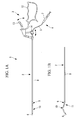
- the treatment instrument 1 includes a rigid rod-shaped insertion section 2 and a manipulating section 3 secured to the proximal end of the insertion section 2 and manipulated by the operator.
- the insertion section 2 is formed as a hollow member so that a flexible treatment device 4 can be inserted into the insertion section 2 so as to be movable.
- the treatment device 4 includes an elongated catheter 5, a rigid injection needle 6 attached to the distal end of the catheter 5, and a syringe 7 attached to the proximal end of the catheter 5 and containing, for example, a drug solution or stem cells.
- the insertion section 2 includes a main body 8 formed in the shape of a straight rod extending from the proximal end toward the distal end, a first curved portion 9 disposed at the distal end of the main body 8 and curved in one direction, and a second curved portion 10 disposed on the distal side of the first curved portion 9 and curved in the direction opposite to the direction in which the first curved portion 9 is curved.
- the first curved portion 9 forms a shoulder portion 11 at the distal end of the main body 8.
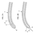
- the first curved portion 9 and the second curved portion 10 are formed by curving the main body 8, which extends from the proximal end in the shape of a straight rod, twice in the same plane (hereinafter referred to as "plane of curvature"). Accordingly, a distal tip (treatment part) 2a of the insertion section 2 on the distal side of the second curved portion 10 makes a predetermined angle with respect to the longitudinal axis of the main body 8.
- the predetermined angle is, for example, 15° to 60°.
- the predetermined angle of the distal tip 2a with respect to the longitudinal axis of the main body 8 preferably falls within the above angular range.
- the curvatures of the first curved portion 9 and the second curved portion 10 are set so that the injection needle 6, which is the rigid portion of the flexible treatment device 4 movable therethrough, can be smoothly moved.
- the radius of curvature of the second curved portion 10 is set to be lower than the radius of curvature of the outer surface of the target organ A to be treated.
- the second curved portion 10 can be separated from the surface of the target organ A with the first curved portion 9 remaining in contact with the surface of the target organ A, thus ensuring sufficient treatment space near the surface of the target organ A.
- the target organ A is the heart (hereinafter referred to as "heart A")
- heart A the target organ A
- sufficient treatment space can be ensured by bringing the first curved portion 9 of the insertion section 2 inserted between the heart A and the pericardium into contact with the surface of the heart A and pressing the pericardium with the second curved portion 10 in a direction away from the heart A.
- the maximum separation distance between the main body 8 and the second curved portion 10 be limited to 30 mm because excessively expanding the space between the heart A and the pericardium could result in complications such as cardiac tamponade.
- the manipulating section 3 includes a handle 12 gripped by the operator, such as a physician, and a lever (switch) 13 pivotably disposed on the handle 12.
- the handle 12 is shaped and sized so as to be easily gripped in the right hand.
- the handle 12 is disposed so as to extend substantially along an extension of the longitudinal axis of the main body 8 of the insertion section 2.
- the handle 12 is disposed such that, when the operator grips the handle 12 in the right hand with an overhand grip, the main body 8 extends in the direction in which the forefinger to the little finger of the right hand are arranged.
- the lever 13 is pivotably disposed at the position corresponding to the forefinger of the right hand gripping the handle 12.
- the operator can grip the handle 12 in all the five fingers and the palm with a powerful grip.
- the operator can pivot the lever 13 with the forefinger while gripping the handle 12 in the four fingers other than the forefinger and the palm.
- a securing section 14 is secured to the lever 13.
- the securing section 14 is movable in a direction toward or away from an opening (not shown) at the proximal end of the main body 8 as the lever 13 is pivoted.
- the securing section 14 includes two members 14a and 14b that can be combined together.
- the securing section 14 allows the treatment device 4 to be secured by holding a certain position of the catheter 5 of the treatment device 4 between curved surfaces 14c and 14d of the members 14a and 14b, respectively. That is, as the lever 13 is pivoted with the certain position of the catheter 5 being secured to the securing section 14, the treatment device 4 is pushed or drawn in the longitudinal direction thereof so that the injection needle 6 at the distal end is extended from or retracted into a distal opening 2b of the insertion section 2.
- the plane of pivoting of the lever 13 disposed on the manipulating section 3 extends in a direction perpendicular to the plane of curvature of the insertion section 2.
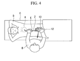
- the treatment instrument 1 For treatment of the target organ A, for example, the heart, by using the treatment instrument 1 according to this embodiment, as shown in Fig. 4 , an operator B stands to the right of a patient D lying spine on a bed C while holding the treatment instrument 1 by gripping the handle 12 in the right hand. The operator B then inserts the distal end of the insertion section 2 into the pericardial cavity through a sheath E passed from under the xiphoid process into the pericardial cavity substantially along the midline of the patient D in the cranial direction.
- the operator B can easily guide the distal end of the insertion section 2 to the heart A by straightening out the wrist with the back of the right hand facing upward and pushing the handle 12, gripped in all the fingers and the palm with an overhand grip, in the direction toward the distal end of the insertion section 2. In some cases, the operator B grips the sheath E or the insertion section 2 in the left hand.
- the distal tip 2a of the insertion section 2 guided into the pericardial cavity through the sheath E is brought into contact with the surface of the heart A.
- the insertion section 2 has the shoulder portion 11 formed by the first curved portion 9 at the distal end of the straight-rod-shaped main body 8, the shoulder portion 11 is brought into contact with the surface of the heart A so that the insertion section 2 is stably supported at two points, namely, the contact portion and the handle 12 outside the body.
- the distal tip 2a of the insertion section 2 can then be located at different positions on the surface of the heart A by manipulating the position of the handle 12 and the angle of the main body 8 about the longitudinal direction thereof such that the point of contact between the heart A and the shoulder portion 11 serves as a fulcrum.
- the distal tip 2a of the insertion section 2 is brought into contact with the surface of the heart A so that the insertion section 2 comes into contact with the surface of the heart A at two points, namely, the shoulder portion 11 formed by the first curved portion 9 and the distal tip 2a. This further stabilizes the orientation of the insertion section 2 for more precise treatment.
- the operator B pushes the catheter 5 of the treatment device 4 by pulling the lever 13 disposed on the handle 12 with the forefinger of the right hand to move the securing section 14 in the direction toward the proximal end of the insertion section 2, thus extending the injection needle 6 at the distal end of the catheter 5 from the distal opening 2b of the insertion section 2, as shown in Fig. 5B .
- the injection needle 6 is extended and punctured the surface of the heart A at an appropriate angle with respect to the surface of the heart A.
- the operator B can then inject, for example, a drug solution into the surface of the heart A by manipulating the syringe 7 with the left hand for proper treatment.
- the operator B can stably inject the drug solution into a plurality of intended sites on the surface of the heart A by repeatedly manipulating the lever 13 and the syringe 7 while changing the position and angle of the handle 12.
- the insertion section 2 transmits heartbeats from the heart A to the hands of the operator B via the distal tip 2a of the insertion section 2 in contact with the surface of the heart A.
- the insertion section 2 is affected by the respiratory movement of the thorax and the diaphragm. Under such conditions where the operator B has difficulty in handling the insertion section 2 as he or she wishes, he or she must accurately perform treatment such as, for example, injection of drug solution or stem cells into a boundary region between a myocardial infarction site and a normal site in the left ventricle at intervals of several millimeters.
- the treatment instrument 1 provides the advantage of facilitating the procedure of positioning the distal tip 2a of the insertion section 2 at various positions on the target organ A and allowing the positioning thereof to be stably maintained for treatment with accurate positioning.
- the treatment device 4 illustrated in this embodiment has the injection needle 6 at the distal end of the catheter 5, the treatment device used is not limited thereto; it may instead be an ablation catheter, for cauterizing the target organ A, having electrodes (not shown) at the distal end thereof.
- a pair of electrodes (not shown) insulated from each other may be disposed at the distal tip 2a of the insertion section 2 to cauterize the injection hole of the injection needle 6 by means of radio-frequency current after the injection of, for example, drug solution or stem cells through the catheter 5, thereby preventing leakage of the drug solution or stem cells.
- the means for cauterizing the injection hole it may be cauterized by light irradiation instead of using electrodes.
- a cooling mechanism (not shown) for refluxing a coolant, such as physiological saline, through the insertion section 2 may be provided to prevent an excessive rise in the temperature of the target site during cauterization.
- the insertion section 2 illustrated has a hollow structure into which the treatment device 4 is inserted so as to be movable
- a solid insertion section may be used instead. That is, a rigid treatment device having a treatment part, such as electrodes (not shown), at the distal end thereof and having a curved shape that comes into contact with the target organ A at two points may itself be used as the insertion section 2.
- the securing section 14 is unnecessary, and the lever 13 may be replaced with, for example, a pushbutton switch.
- the distal end of the insertion section 2 is preferably located on an extension of the main body 8, the position is not limited thereto; it may be freely set depending on, for example, the type and shape of the target organ A and the angle at which the treatment device 4 is extended.
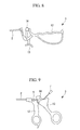
- the shape of the manipulating section 3 is not limited to the structure shown in Fig. 1A ; a manipulating section 3 having any shape can be used, as illustrated in Figs. 6 to 10 .
- the manipulating section 3 in Fig. 6 is the "scissors type," which allows delicate manipulation as does conventional forceps, and is configured so that the thumb is secured to the lever 13 for manipulating the treatment device 4 with the handle 12 gripped with an overhand grip.
- the manipulating section 3 in Fig. 7 includes a handle 12 to grip with an overhand grip similar to the manipulating section 3 in Fig. 1A , but the securing section 14 is located at a different position.
- the manipulating section 3 in Fig. 8 includes a handle 12 to grip with an overhand grip similar to the manipulating section 3 in Fig. 1A , but the lever 13 is manipulated with the thumb.
- the manipulating section 3 in Fig. 9 includes a "scissors type" handle 12 similar to the manipulating section 3 in Fig. 6 , but the handle 12 and the lever 13 are reversed in position so that the direction of the hand gripping the handle 12 differs from the overhand grip of the manipulating section 3 in Fig. 6 .
- the manipulating section 3 in Fig. 10 includes a lever 13 built into the handle 12. The operator B can manipulate the treatment device 4 by gripping the handle 12 and the lever 13 in the entire palm for improved grip stability.
- a movable portion 15 or 16 may instead be provided near the distal end of the insertion section 2.
- the movable portion 15 is provided in the second curved portion 10 so as to be variable in curvature, and a manipulating member 17 for operating the movable portion 15 is provided on the manipulating section 3.
- the movable portion 16 is provided in the first curved portion 9 so as to be variable in curvature, and a manipulating member 17 for operating the movable portion 16 is provided on the manipulating section 3. This allows the movable portion 15 or 16 to be operated to change the angle of the distal tip 2a of the insertion section 2 and therefore the angle at which the treatment device 4 is extended for more complicated treatment of the target organ A.
- the angle ⁇ between the longitudinal axis of the main body 8 of the insertion section 2 and the handle 12 may be set to a certain angle appropriate for manipulation so that the operator B does not easily get tired, for improved ease of manipulation.
- the angle between the longitudinal axis of the main body 8 and the handle 12 may be freely variable with, for example, a ball-link mechanism (not shown).
- the plane of pivoting of the lever 13 is perpendicular to the plane of curvature of the insertion section 2 in the example shown in Fig. 1A .
- This angle is appropriate for approach to the anterior wall of the left ventricle; instead, for approach to the posterior wall of the left ventricle or another site, any other angle appropriate for the target site to be approached may be set.
- the angle between the insertion section 2 and the handle 12 may be freely adjustable so that an appropriate angle can be set depending on, for example, the target organ A.
- the treatment device 4 used can be, for example, a disposable puncture needle, an ablation catheter, a tube, a balloon, a laser therapy device, an optical fiber, or an ultrasonic probe.
- the securing section 14, for securing and advancing/retracting the treatment device 4, illustrated in Figs. 3A and 3B has the curved surfaces 14c and 14d between which the treatment device 4 is held, it may instead be held between flat surfaces or curved surfaces on which, for example, rubber is laminated for increased friction.
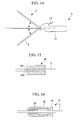
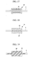
- the securing section 14 is not limited to the above structure; the structures shown in Figs. 15 to 21 may be used instead.
- the catheter 5 of the treatment device 4 is held between contact surfaces 14a' and 14b' having irregularities.
- a cylindrical sleeve 20 formed of silicone rubber is disposed between a housing 18 and a plug 19 through which the catheter 5 of the treatment device 4 is passed and is deformed by tightening the plug 19 into the housing 18 so that the inner diameter of the sleeve 20 becomes smaller, thus securing the catheter 5 of the treatment device 4.
- a box-shaped securing section 14 through which the catheter 5 is passed is filled with an adhesive 21 to bond and secure the catheter 5.
- the catheter 5 is held between magnets 22 and 23 and is secured by magnetic attraction.
- the catheter 5 is secured to the securing section 14 with an adhesive tape 24.
- an adaptor 25 or 26 having a protrusion or recess may be secured to the catheter 5, and the catheter 5 may be secured to the securing section 14 by fitting the protrusion or recess to a corresponding recess or protrusion of the securing section 14.
- the handle 12 may instead be configured to be suitable for the operator B to grip in the left hand while standing to the left of the patient D lying spine on the bed C.
Landscapes
- Health & Medical Sciences (AREA)
- Surgery (AREA)
- Engineering & Computer Science (AREA)
- Life Sciences & Earth Sciences (AREA)
- Medical Informatics (AREA)
- General Health & Medical Sciences (AREA)
- Nuclear Medicine, Radiotherapy & Molecular Imaging (AREA)
- Plasma & Fusion (AREA)
- Biomedical Technology (AREA)
- Heart & Thoracic Surgery (AREA)
- Physics & Mathematics (AREA)
- Molecular Biology (AREA)
- Animal Behavior & Ethology (AREA)
- Otolaryngology (AREA)
- Public Health (AREA)
- Veterinary Medicine (AREA)
- Surgical Instruments (AREA)
- Media Introduction/Drainage Providing Device (AREA)
- Infusion, Injection, And Reservoir Apparatuses (AREA)
- Dental Prosthetics (AREA)
- Dental Tools And Instruments Or Auxiliary Dental Instruments (AREA)
Applications Claiming Priority (3)
| Application Number | Priority Date | Filing Date | Title |
|---|---|---|---|
| US29742310P | 2010-01-22 | 2010-01-22 | |
| JP2010162989A JP2011147758A (ja) | 2010-01-22 | 2010-07-20 | 処置具 |
| PCT/JP2011/050176 WO2011089935A2 (fr) | 2010-01-22 | 2011-01-07 | Outil de traitement |
Publications (2)
| Publication Number | Publication Date |
|---|---|
| EP2526993A2 true EP2526993A2 (fr) | 2012-11-28 |
| EP2526993A4 EP2526993A4 (fr) | 2017-04-05 |
Family
ID=44535312
Family Applications (1)
| Application Number | Title | Priority Date | Filing Date |
|---|---|---|---|
| EP11734542.1A Withdrawn EP2526993A4 (fr) | 2010-01-22 | 2011-01-07 | Outil de traitement |
Country Status (5)
| Country | Link |
|---|---|
| US (1) | US20110184378A1 (fr) |
| EP (1) | EP2526993A4 (fr) |
| JP (1) | JP2011147758A (fr) |
| CN (1) | CN102711896B (fr) |
| WO (1) | WO2011089935A2 (fr) |
Families Citing this family (20)
| Publication number | Priority date | Publication date | Assignee | Title |
|---|---|---|---|---|
| CN107007348B (zh) | 2010-10-25 | 2019-05-31 | 美敦力Af卢森堡有限责任公司 | 用于神经调节治疗的估算及反馈的装置、系统及方法 |
| DE102011085512A1 (de) * | 2011-10-31 | 2013-05-02 | Richard Wolf Gmbh | Handhabe für ein medizinisches Instrument |
| EP3348220B1 (fr) | 2012-03-08 | 2024-10-23 | Medtronic Ardian Luxembourg S.à.r.l. | Échantillonnage de biomarqueurs dans le contexte de dispositifs de neuromodulation et systèmes et procédés associés |
| US20130324911A1 (en) * | 2012-05-31 | 2013-12-05 | Covidien Lp | Ablation device with drug delivery component |
| US9044254B2 (en) | 2012-08-07 | 2015-06-02 | Covidien Lp | Microwave ablation catheter and method of utilizing the same |
| US10543037B2 (en) | 2013-03-15 | 2020-01-28 | Medtronic Ardian Luxembourg S.A.R.L. | Controlled neuromodulation systems and methods of use |
| US9339332B2 (en) | 2013-08-30 | 2016-05-17 | Medtronic Ardian Luxembourg S.A.R.L. | Neuromodulation catheters with nerve monitoring features for transmitting digital neural signals and associated systems and methods |
| US9326816B2 (en) | 2013-08-30 | 2016-05-03 | Medtronic Ardian Luxembourg S.A.R.L. | Neuromodulation systems having nerve monitoring assemblies and associated devices, systems, and methods |
| US10610292B2 (en) | 2014-04-25 | 2020-04-07 | Medtronic Ardian Luxembourg S.A.R.L. | Devices, systems, and methods for monitoring and/or controlling deployment of a neuromodulation element within a body lumen and related technology |
| WO2016033543A1 (fr) | 2014-08-28 | 2016-03-03 | Medtronic Ardian Luxembourg S.A.R.L. | Procédés d'évaluation de l'efficacité d'une neuromodulation rénale et systèmes et dispositifs associés |
| US10368775B2 (en) | 2014-10-01 | 2019-08-06 | Medtronic Ardian Luxembourg S.A.R.L. | Systems and methods for evaluating neuromodulation therapy via hemodynamic responses |
| WO2016100720A1 (fr) | 2014-12-17 | 2016-06-23 | Medtronic Ardian Luxembourg S.A.R.L. | Systèmes et procédés d'évaluation du tonus du système nerveux sympathique pour une thérapie de neuromodulation rénale |
| US10327791B2 (en) * | 2015-10-07 | 2019-06-25 | Medtronic Vascular, Inc. | Occlusion bypassing apparatus with a re-entry needle and a distal stabilization balloon |
| MX2018010821A (es) | 2016-03-10 | 2019-02-07 | Human Extensions Ltd | Unidad de control para dispositivo medico. |
| US10231784B2 (en) | 2016-10-28 | 2019-03-19 | Medtronic Ardian Luxembourg S.A.R.L. | Methods and systems for optimizing perivascular neuromodulation therapy using computational fluid dynamics |
| US12082917B2 (en) | 2018-01-24 | 2024-09-10 | Medtronic Ireland Manufacturing Unlimited Company | Systems, devices, and methods for assessing efficacy of renal neuromodulation therapy |
| US11633120B2 (en) | 2018-09-04 | 2023-04-25 | Medtronic Ardian Luxembourg S.A.R.L. | Systems and methods for assessing efficacy of renal neuromodulation therapy |
| CN110960314B (zh) * | 2019-12-31 | 2021-06-15 | 杭州堃博生物科技有限公司 | 检测机构、射频消融导管及射频消融系统 |
| JP2021108956A (ja) * | 2020-01-10 | 2021-08-02 | 朝日インテック株式会社 | カテーテル、及び、カテーテルシステム |
| JP7785061B2 (ja) * | 2021-03-11 | 2025-12-12 | 株式会社ヨコオ | 焼灼穿刺針 |
Family Cites Families (13)
| Publication number | Priority date | Publication date | Assignee | Title |
|---|---|---|---|---|
| JP2793884B2 (ja) | 1990-04-25 | 1998-09-03 | オリンパス光学工業株式会社 | 硬性内視鏡 |
| US5152749A (en) * | 1991-06-28 | 1992-10-06 | American Medical Systems, Inc. | Instrument placement apparatus |
| US5536267A (en) * | 1993-11-08 | 1996-07-16 | Zomed International | Multiple electrode ablation apparatus |
| US5827216A (en) * | 1995-06-07 | 1998-10-27 | Cormedics Corp. | Method and apparatus for accessing the pericardial space |
| CA2280812A1 (fr) * | 1997-02-13 | 1998-08-20 | Rodney Brenneman | Dispositifs percutanes et hiataux et leurs procedes d'utilisation en chirurgie pelvienne peu vulnerante |
| JP2001346750A (ja) * | 2000-06-06 | 2001-12-18 | Olympus Optical Co Ltd | 内視鏡 |
| US20040167558A1 (en) * | 2000-07-26 | 2004-08-26 | Igo Stephen R. | Method and apparatus for accessing the pericardial space |
| EP1363700A4 (fr) * | 2001-01-11 | 2005-11-09 | Rita Medical Systems Inc | Instrument et procede de traitement de l'os |
| US7610104B2 (en) * | 2002-05-10 | 2009-10-27 | Cerebral Vascular Applications, Inc. | Methods and apparatus for lead placement on a surface of the heart |
| JP2006006421A (ja) * | 2004-06-23 | 2006-01-12 | Pentax Corp | 硬性内視鏡の挿入部 |
| US8409175B2 (en) * | 2005-07-20 | 2013-04-02 | Woojin Lee | Surgical instrument guide device |
| US7623899B2 (en) * | 2005-09-16 | 2009-11-24 | Biosense Webster, Inc. | Catheter with flexible pre-shaped tip section |
| US20090171147A1 (en) * | 2007-12-31 | 2009-07-02 | Woojin Lee | Surgical instrument |
-
2010
- 2010-07-20 JP JP2010162989A patent/JP2011147758A/ja active Pending
-
2011
- 2011-01-07 EP EP11734542.1A patent/EP2526993A4/fr not_active Withdrawn
- 2011-01-07 WO PCT/JP2011/050176 patent/WO2011089935A2/fr not_active Ceased
- 2011-01-07 CN CN201180006426.2A patent/CN102711896B/zh not_active Expired - Fee Related
- 2011-01-18 US US13/008,385 patent/US20110184378A1/en not_active Abandoned
Non-Patent Citations (1)
| Title |
|---|
| See references of WO2011089935A2 * |
Also Published As
| Publication number | Publication date |
|---|---|
| WO2011089935A3 (fr) | 2011-09-15 |
| CN102711896B (zh) | 2016-05-04 |
| EP2526993A4 (fr) | 2017-04-05 |
| WO2011089935A2 (fr) | 2011-07-28 |
| JP2011147758A (ja) | 2011-08-04 |
| CN102711896A (zh) | 2012-10-03 |
| US20110184378A1 (en) | 2011-07-28 |
Similar Documents
| Publication | Publication Date | Title |
|---|---|---|
| US20110184378A1 (en) | Treatment instrument and treatment method | |
| EP2670471B1 (fr) | Système de cathéter orientable à un seul fil continu | |
| CN101374465B (zh) | 消融装置与将消融装置引导至体内的系统 | |
| US8512227B2 (en) | Apparatus for assisting operations of medical instrument attached to endoscope | |
| JP4690426B2 (ja) | 組織剥離チップ及びこれを備える剥離装置 | |
| JP5792416B1 (ja) | 内視鏡処置システム | |
| EP1987794B1 (fr) | Instrument de traitement endoscopique | |
| JP5394951B2 (ja) | 穿刺針ガイド器具 | |
| JP2015047376A (ja) | 穿刺機能付きチューブ器具 | |
| JP6013672B1 (ja) | 内視鏡システム | |
| WO2019202699A1 (fr) | Dispositif médical | |
| EP1847231B1 (fr) | Pince bipolaire souple | |
| KR200478381Y1 (ko) | 조직 치료를 위한 일회용 전자 수술 핸드피스 | |
| JP2007500035A (ja) | 組織切除プローブの案内カテーテル | |
| CN105228543B (zh) | 切开器具 | |
| US11931565B2 (en) | Surgical application tool for implantation of an electrode wire | |
| JP6062118B2 (ja) | 補助具及び内視鏡システム | |
| JP7055892B2 (ja) | 内視鏡用処置具 | |
| JP6628553B2 (ja) | 内視鏡用高周波処置具 | |
| US20250352258A1 (en) | Energy treatment medical devices and energy treatment methods | |
| US20220354515A1 (en) | Endoscopic side snare tools and methods for use | |
| JPH11318926A (ja) | 高周波治療用処置具 | |
| WO2026080662A1 (fr) | Dispositifs médicaux de traitement à l'énergie et procédés de traitement à l'énergie | |
| KR20240116177A (ko) | 의료용 바이폴라 스네어 |
Legal Events
| Date | Code | Title | Description |
|---|---|---|---|
| PUAI | Public reference made under article 153(3) epc to a published international application that has entered the european phase |
Free format text: ORIGINAL CODE: 0009012 |
|
| 17P | Request for examination filed |
Effective date: 20120627 |
|
| AK | Designated contracting states |
Kind code of ref document: A2 Designated state(s): AL AT BE BG CH CY CZ DE DK EE ES FI FR GB GR HR HU IE IS IT LI LT LU LV MC MK MT NL NO PL PT RO RS SE SI SK SM TR |
|
| DAX | Request for extension of the european patent (deleted) | ||
| RAP1 | Party data changed (applicant data changed or rights of an application transferred) |
Owner name: OLYMPUS CORPORATION |
|
| RAP1 | Party data changed (applicant data changed or rights of an application transferred) |
Owner name: OLYMPUS CORPORATION |
|
| RIN1 | Information on inventor provided before grant (corrected) |
Inventor name: OKAZAKI, YOSHIRO Inventor name: KOBAYASHI, MASAYUKI |
|
| A4 | Supplementary search report drawn up and despatched |
Effective date: 20170303 |
|
| RIC1 | Information provided on ipc code assigned before grant |
Ipc: A61B 18/12 20060101ALI20170227BHEP Ipc: A61M 25/01 20060101AFI20170227BHEP Ipc: A61M 31/00 20060101ALI20170227BHEP |
|
| STAA | Information on the status of an ep patent application or granted ep patent |
Free format text: STATUS: EXAMINATION IS IN PROGRESS |
|
| 17Q | First examination report despatched |
Effective date: 20180905 |
|
| STAA | Information on the status of an ep patent application or granted ep patent |
Free format text: STATUS: THE APPLICATION IS DEEMED TO BE WITHDRAWN |
|
| 18D | Application deemed to be withdrawn |
Effective date: 20190116 |