EP2527575A2 - Ferrure de porte coulissante - Google Patents
Ferrure de porte coulissante Download PDFInfo
- Publication number
- EP2527575A2 EP2527575A2 EP12169204A EP12169204A EP2527575A2 EP 2527575 A2 EP2527575 A2 EP 2527575A2 EP 12169204 A EP12169204 A EP 12169204A EP 12169204 A EP12169204 A EP 12169204A EP 2527575 A2 EP2527575 A2 EP 2527575A2
- Authority
- EP
- European Patent Office
- Prior art keywords
- sliding
- carriage
- sliding door
- door fitting
- guide
- Prior art date
- Legal status (The legal status is an assumption and is not a legal conclusion. Google has not performed a legal analysis and makes no representation as to the accuracy of the status listed.)
- Granted
Links
- 238000006073 displacement reaction Methods 0.000 claims abstract description 60
- 238000011010 flushing procedure Methods 0.000 claims description 6
- 230000000284 resting effect Effects 0.000 claims description 2
- 230000008878 coupling Effects 0.000 description 17
- 238000010168 coupling process Methods 0.000 description 17
- 238000005859 coupling reaction Methods 0.000 description 17
- 230000002093 peripheral effect Effects 0.000 description 7
- 239000000969 carrier Substances 0.000 description 3
- 230000000087 stabilizing effect Effects 0.000 description 3
- 238000005452 bending Methods 0.000 description 2
- 230000006835 compression Effects 0.000 description 2
- 238000007906 compression Methods 0.000 description 2
- 210000003746 feather Anatomy 0.000 description 2
- 230000005540 biological transmission Effects 0.000 description 1
- IHQKEDIOMGYHEB-UHFFFAOYSA-M sodium dimethylarsinate Chemical class [Na+].C[As](C)([O-])=O IHQKEDIOMGYHEB-UHFFFAOYSA-M 0.000 description 1
- 230000000007 visual effect Effects 0.000 description 1
Images














Classifications
-
- E—FIXED CONSTRUCTIONS
- E05—LOCKS; KEYS; WINDOW OR DOOR FITTINGS; SAFES
- E05D—HINGES OR SUSPENSION DEVICES FOR DOORS, WINDOWS OR WINGS
- E05D15/00—Suspension arrangements for wings
- E05D15/06—Suspension arrangements for wings for wings sliding horizontally more or less in their own plane
- E05D15/10—Suspension arrangements for wings for wings sliding horizontally more or less in their own plane movable out of one plane into a second parallel plane
- E05D15/1042—Suspension arrangements for wings for wings sliding horizontally more or less in their own plane movable out of one plane into a second parallel plane with transversely moving carriage
-
- E—FIXED CONSTRUCTIONS
- E05—LOCKS; KEYS; WINDOW OR DOOR FITTINGS; SAFES
- E05D—HINGES OR SUSPENSION DEVICES FOR DOORS, WINDOWS OR WINGS
- E05D15/00—Suspension arrangements for wings
- E05D15/06—Suspension arrangements for wings for wings sliding horizontally more or less in their own plane
- E05D15/10—Suspension arrangements for wings for wings sliding horizontally more or less in their own plane movable out of one plane into a second parallel plane
- E05D2015/1028—Suspension arrangements for wings for wings sliding horizontally more or less in their own plane movable out of one plane into a second parallel plane with only the wing moving transversely
- E05D2015/1039—Suspension arrangements for wings for wings sliding horizontally more or less in their own plane movable out of one plane into a second parallel plane with only the wing moving transversely the wing sliding transversely on the carriage
-
- E—FIXED CONSTRUCTIONS
- E05—LOCKS; KEYS; WINDOW OR DOOR FITTINGS; SAFES
- E05Y—INDEXING SCHEME ASSOCIATED WITH SUBCLASSES E05D AND E05F, RELATING TO CONSTRUCTION ELEMENTS, ELECTRIC CONTROL, POWER SUPPLY, POWER SIGNAL OR TRANSMISSION, USER INTERFACES, MOUNTING OR COUPLING, DETAILS, ACCESSORIES, AUXILIARY OPERATIONS NOT OTHERWISE PROVIDED FOR, APPLICATION THEREOF
- E05Y2201/00—Constructional elements; Accessories therefor
- E05Y2201/60—Suspension or transmission members; Accessories therefor
- E05Y2201/622—Suspension or transmission members elements
- E05Y2201/64—Carriers
-
- E—FIXED CONSTRUCTIONS
- E05—LOCKS; KEYS; WINDOW OR DOOR FITTINGS; SAFES
- E05Y—INDEXING SCHEME ASSOCIATED WITH SUBCLASSES E05D AND E05F, RELATING TO CONSTRUCTION ELEMENTS, ELECTRIC CONTROL, POWER SUPPLY, POWER SIGNAL OR TRANSMISSION, USER INTERFACES, MOUNTING OR COUPLING, DETAILS, ACCESSORIES, AUXILIARY OPERATIONS NOT OTHERWISE PROVIDED FOR, APPLICATION THEREOF
- E05Y2800/00—Details, accessories and auxiliary operations not otherwise provided for
- E05Y2800/20—Combinations of elements
- E05Y2800/205—Combinations of elements forming a unit
-
- E—FIXED CONSTRUCTIONS
- E05—LOCKS; KEYS; WINDOW OR DOOR FITTINGS; SAFES
- E05Y—INDEXING SCHEME ASSOCIATED WITH SUBCLASSES E05D AND E05F, RELATING TO CONSTRUCTION ELEMENTS, ELECTRIC CONTROL, POWER SUPPLY, POWER SIGNAL OR TRANSMISSION, USER INTERFACES, MOUNTING OR COUPLING, DETAILS, ACCESSORIES, AUXILIARY OPERATIONS NOT OTHERWISE PROVIDED FOR, APPLICATION THEREOF
- E05Y2800/00—Details, accessories and auxiliary operations not otherwise provided for
- E05Y2800/20—Combinations of elements
- E05Y2800/21—Combinations of elements of identical elements, e.g. of identical compression springs
-
- E—FIXED CONSTRUCTIONS
- E05—LOCKS; KEYS; WINDOW OR DOOR FITTINGS; SAFES
- E05Y—INDEXING SCHEME ASSOCIATED WITH SUBCLASSES E05D AND E05F, RELATING TO CONSTRUCTION ELEMENTS, ELECTRIC CONTROL, POWER SUPPLY, POWER SIGNAL OR TRANSMISSION, USER INTERFACES, MOUNTING OR COUPLING, DETAILS, ACCESSORIES, AUXILIARY OPERATIONS NOT OTHERWISE PROVIDED FOR, APPLICATION THEREOF
- E05Y2800/00—Details, accessories and auxiliary operations not otherwise provided for
- E05Y2800/73—Multiple functions
-
- E—FIXED CONSTRUCTIONS
- E05—LOCKS; KEYS; WINDOW OR DOOR FITTINGS; SAFES
- E05Y—INDEXING SCHEME ASSOCIATED WITH SUBCLASSES E05D AND E05F, RELATING TO CONSTRUCTION ELEMENTS, ELECTRIC CONTROL, POWER SUPPLY, POWER SIGNAL OR TRANSMISSION, USER INTERFACES, MOUNTING OR COUPLING, DETAILS, ACCESSORIES, AUXILIARY OPERATIONS NOT OTHERWISE PROVIDED FOR, APPLICATION THEREOF
- E05Y2900/00—Application of doors, windows, wings or fittings thereof
- E05Y2900/20—Application of doors, windows, wings or fittings thereof for furniture, e.g. cabinets
Definitions
- the invention relates to a sliding door fitting for a sliding door cabinet, wherein a first of at least two sliding leaves of a flushing position, in which the front side of the first sash substantially flush with the front of the second sash, via an offset position in which the front side of the first sash against the front of the second sliding leaf is offset transversely to the direction of displacement, in the direction of displacement over the second sliding sash in an open position is displaceable, with a control lever to from an initial displacement distance of the first sash in the initial phase of the opening movement or in the final phase of the closing movement of the first sliding sash to control an offset distance in the offset position or in the flush position, wherein the control lever displaceable transversely to the running rail extension on a displaceable along a running rail carriage Has carriage engaging output arm and a cooperating with a stop drive arm.
- the DE 37 16 876 C2 describes a fitting for sliding doors.
- the fitting there is provided for a sliding door system, in which the doors are arranged in the closed state in a plane next to each other.
- a sliding door system in which the doors are arranged in the closed state in a plane next to each other.
- the door To open a cabinet equipped with such a sliding door system, one of the doors from the flushing position must be brought into an offset position.
- the door must be displaced substantially transversely to its extension plane, so that it can be pushed from the offset position on the other door out into an open position.
- a sliding holder is firmly connected to the sliding sash. This rests on a roller table, so that it can be displaced in a direction transverse to the extension direction of the track rail.
- To control two control levers are provided.
- the EP 0195 880 also describes a sliding door fitting in which a sliding sash must be moved from a flushing position into an offset position before the sliding sash can be pushed into an open position.
- an angle lever is provided to control the offset movement.
- the DE 10 2010 016 040 describes a drive device with a toothed belt to shift a sliding door of a sliding door cabinet back and forth between an open position and a closed position.
- the invention has for its object to provide a nutzsvorteilhafteren sliding door fitting.
- the length of the drive arm and the length of the driven arm are each dimensioned so that the offset distance is at least twice as large as the initial displacement distance. According to this embodiment, it is possible, for example, on a displacement of about 15 mm to move the sliding sash by about 40 mm.
- the control lever is an angle lever with a pivoting lever mounted on the carcass or on the carriage.
- the drive arm can be half as long as the output arm. Is the angle lever on Carriage hinged, so the axis of its pivot bearing preferably passes through a slot of the carriage.
- the stop may be formed by a stop carrier. This can be attached at any point on the body or on a screwed onto the top floor of the carcass support profile.
- the attachment of the stop carrier on the body can be done by means of screws.
- the position of the stop carrier can be determined during assembly.
- the sliding leaf can be brought into its closed position and secured in this position, the stop carrier on the body or support section.
- a development of the invention relates to a securing element.
- This securing element prevents the carriage from shifting in an open position of the sliding leaf relative to the carriage. In the closed position of the sliding leaf, the securing element assumes a non-operative position. In this position, the carriage can move relative to the carriage.
- the securing element is acted upon by a spring. It can be brought, for example by the force of the spring after reaching the offset position of the non-operative position in the operative position.
- the return displacement of the securing element in the Fishwirk too takes place when closing the sliding leaf, for example, characterized in that abuts a stop of the securing element on the stop carrier.
- the securing element is then controlled in the final phase of the closing of the sliding leaf from a securing position to a release position.
- the securing element can be attached to the carriage. It is preferably designed as a sliding cam.
- the sliding cam is displaceable parallel to the displacement direction of the carriage.
- the particular corpusfeste, namely sitting on the stop carrier stop, which controls the drive arm in the offset position can form a control cam.
- the control cam can be designed such that the drive arm undergoes a specific movement curve during the initial displacement.
- the control cam may be designed in such a way that at the beginning of the initial displacement the sliding sash makes a larger offset displacement per displacement path than to complete the initial shift. This has the consequence that the gap between the narrow sides of two sliding doors can occupy a minimum distance.
- the stop carrier tooth-like engages in a tooth gap formed between two output arms.
- the underbody is assigned a guide device. This has a hinged on the sliding leaf guide lever. Along the lower edge of the subfloor runs a guide bar. At least one, but preferably two guide rollers are supported there. There is a tax role provided. This is before the initial shift with the sliding sash closed in front of a web edge. The web edge can be bevelled. In the course of the initial displacement, the guide roller rolls off at the web edge and overflows the web edge, to then roll along the guide web, while holding the guide lever in a pivoted position.
- the invention further forms a generic sliding door fitting further such that the sliding leaf can be opened or closed with a motor.
- a drive device engages the carriage in order to displace the carriage in the extension direction of the running rail.
- the control lever is pivotable about a pivot bearing, which is assigned to the body stationary.
- the control lever should be pivoted by acting on the sliding sash.
- Such a transmission may be provided both on an upper guide and on a lower guide of the sliding leaf.
- the upper guide has a on the body, in particular attached to the ceiling plate of the cabinet running rail, along which a carriage is guided.
- the carriage carries a transversely displaceable to the displacement carriage on which the sliding sash is attached.
- a guide rail may be provided to hold the sliding leaf in the sliding movement in a distance position to the second sliding sash.
- the displacement movement of the carriage along the running rail derived a transverse movement.
- the carriage arranged displaceably on the carriage is initially displaced essentially transversely to the running-rail extension direction on the carriage.
- the sliding leaf is displaced into the offset position.
- This displacement is derived from a linear displacement of the carriage in the direction of extension of the running rail, so that the sliding leaf can be displaced with a drive device which is of the DE 10 2010 016 040 is described.
- the control lever In a lower guide the control lever is also acted upon by the sliding sash.
- shifting from the offset position in the direction of the open position of the output arm is decoupled from the sliding sash.
- the output arm When shifting back from the open position to the offset position, the output arm is coupled to the sliding sash again.
- the coupling between the output arm and sliding sash is thus detachable when moving the sliding sash from the offset position into the open position.
- the end of the driven arm is designed as a fork. In the flush position or the offset position, the fork is coupled to a coupling element, for example a coupling roller of the sliding leaf.
- the coupling element may be arranged in the upper guide on a two carriages interconnecting traverse.
- the coupling element On a lower guide, the coupling element may be attached to a support plate which is fixedly connected to the sliding leaf.
- the coupling element is in the coupling position in the fork mouth.
- the control lever is driven by a drive arm.
- the drive arm is preferably shorter than the output arm.
- the drive arm is at an angle to the output arm and cooperates with a stop of the carriage.
- two drive arms are provided.
- a first drive arm is acted upon closing the sliding sash of a first stop of the carriage.
- a second drive arm is when opening the sliding sash of a second stop of the carriage applied.
- the stops are formed by a section of the carriage. To open the sliding leaf, the end of the drive arm slides or rolls along the stop, which moves in the extension direction of the running rail.
- Stop and control cam can also be formed by wall sections of a control channel or a control slot.
- a spring element which supports the control lever in its pivotal displacement from the closed position to the offset position.
- the control lever is also held in a Einfang ein in which the coupling element retracts when closing the sliding sash in the fork.
- a securing element is provided in the upper guide, which prevents the carriage moves in an operating position of the sliding sash between offset position and open position relative to the carriage.
- this fuse element may be a locking pin, which passes through an opening of the running rail in the flush position. In the offset position and in any intermediate position between offset position and open position, the end of the pin is in front of a wall, for example, the running rail.
- a driver with which the carriage can be displaced in the extension direction of the running rail can be driven by a toothed belt drive, as already cited above DE 10 2010 016 040 disclosed.
- a lower guide may have a securing element. It may be one or more leadership roles that are firmly connected to the sliding panel at the bottom of the sliding sash, for example, are supported by a support plate.
- To one of these guide rollers correspond one or more guide rails, which may, for example, be L-profiles.
- the guide rails are firmly connected to the underbody of the body.
- the control lever is preferably pivotally mounted on a base plate which is screwed firmly on the top floor or under the bottom of a cabinet body.
- the carriage is preferably guided between two mutually parallel rails.
- the carriage can be moved between the two rails.
- the control lever is located between the two rails, the drive arm is directed away from the pivot bearing from the sliding sash.
- the output arm extends essentially in the direction of travel rail extension.
- the two drive arms extend transversely thereto. In principle, it is sufficient if only one drive arm is provided, on which a stop engages when opening the sliding leaf, which is overrun when leaving the offset position. When closing the sliding leaf engages on this drive arm another stop, which may also have a control cam, to pivot to the control lever.
- each of the two sliding sash each pair of carriages can be assigned. The total of four carriages can run in the same rails.
- the two carriages each sit only in the region of a horizontal half of each sliding sash. While a carriage, for example, sits on the edge of the sliding sash, the second carriage sits approximately in the middle of the sliding sash.
- the carriages are arranged on the respectively facing away from each other halves of the sliding sash so that the sliding sash can almost completely overlap in an open position.
- the two carriages, which are assigned to the respective sliding leaf are preferably assigned to the respectively halves of the wing facing away from one another.
- the two carriages of the left sliding sash lie on the left half of the upper peripheral edge and the two carriages of the right sash on the right half of the upper peripheral edge.
- the sliding sash can optionally be pushed completely over each other.
- the sliding door fitting is used on sliding door cabinets, for example. Bedroom cabinets, living room cabinets but also kitchen cabinets. For large, heavy sliding panels several carriages are used. For smaller, lighter sliding sashes, for example on kitchen cabinets, it is sufficient if the sliding sash hangs on a carriage.
- the track which is mounted on the front edge of the top floor, can perform a shape-stabilizing function. It can have several horizontal webs. By means of a substantially rectangular hollow chamber, the running rail is stabilized against bending.
- the lower guide may consist of a guide channel, which consists of the space between two mutually parallel webs. The channel can form at the beginning of the front edge of the body obliquely rearwardly channel portion in the form of, for example, a bag.
- the pocket walls are inclined.
- this bag is in the closed position a tax role. It may be provided a spring which loads a guide lever, so that the control roller is subjected to force in the pocket pulled.
- the invention relates in addition to the aforementioned development of the prior art and those sliding door fittings of the generic type, which is further developed with the characteristics of a single subclaim.
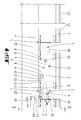
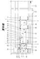
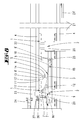
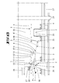
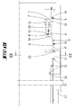
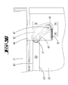
- FIGS. 1 to 13 illustrated embodiment shows a sliding door cabinet with two sliding leaves 21, 21 'and a topsoil 22 to which two rails 4 are attached.
- only one sliding leaf 21 can be brought from a closed position into an offset position by means of the sliding door fitting according to the invention, in the the sliding wing 21 brought into the offset position can be pushed over the other sliding leaf 21 'into an open position.
- the sliding leaf 21 In order to open the second sliding leaf 21 ', the sliding leaf 21 must first of the in Fig. 1 Flattening position shown are brought into an offset position. Then the sliding leaf 21 'can be displaced under the sliding leaf 21.
- both sliding sash 21, 21 'in each case by a flushing position in an offset position can be brought and in the offset position on each of the other sliding sash 21', 21 displaced.
- Each of the two sliding leaves 21, 21 ' is displaceable with a drive device, as shown in the DE 10 2010 016 040 is shown. The disclosure of this document is therefore incorporated in full in this application.
- FIGS. 1 to 12 the different functional positions of the upper guide are shown.
- the two arranged on the top floor 22 rails 4 have a C-profile. From the Fig. 5 it can be seen that the C-shaped profile openings of the running rail 4 face each other. Rollers 18 of a carriage 1 run in the profile openings of the running rail 4. The rollers 18 are carried by roller carriers 17, which are connected to one another by means of a guide rod 19. The guide rod 19 extends in a direction transverse to the extension direction of the running rail 4, which extends in the direction of displacement of the sliding leaf 21, 21 '. In the first embodiment, two carriages 1 are attached to only one of the two sliding panels 21. At the in Fig.
- two carriages 1 are attached to two sliding panels 21, 21 'in each case.
- the two carriages are each mounted on only one half of the sliding leaf 21, 21 ', so that they can run in the same rails 4. They are attached to the halves facing away from each other on the sliding leaf 21, 21 '. From the Fig. 5 It can be seen that the non-displaceable sliding leaf 21 'is slidably guided by a roller 28 on a separate rail section.
- a carriage 2 On the guide rod 19, which is double in the embodiment, a carriage 2 is slidably mounted. On slide 2, the sliding wing 21 is attached via a bracket. The carriage 2 forms a guide block 20, which is penetrated by the two guide rods 19.
- a section 11 of the roller carrier 17 forms a first stop 12 and a second stop 13.
- the second stop 13 forms the wall of a capture opening whose other wall 14 forms a control cam.
- a securing element 26 in the form of a pin.
- the locking pin 26 has a length such that it in the in the Fig. 8 shown offset position is completely pulled out of the opening 27. He prevents the carriage 2, for example, in the in Fig. 10 shown operating position can be displaced so far in the direction of the body of the sliding door cabinet that brought into the offset position sliding sash 21 can abut against the not placed in the offset position sliding sash 21 '. He thus reduces the displacement path of the carriage 2 relative to the carriage. 1
- a base plate 10 On the top floor 22 of the cabinet, a base plate 10 is attached. This base plate 10 is firmly connected to the body of the cabinet. On the base plate 10, a control lever 5 is pivotally mounted about a pivot bearing 9. The control lever 5 has a short drive arm 7, which extends substantially transversely to the direction of displacement of the carriage 1. The control lever 5 also has an approximately four times as long output arm 6, which extends substantially in the direction of displacement of the carriage 1. At its free end, the output arm 6 has a fork 6 '.
- Both drive arms 7, 8 have at their ends rollers 7', 8 '.
- the roller 7 ' cooperates with the stop 12.
- the roller 8 ' is located in the receiving opening between the stop 13 and cam 14th
- a drive device 24 extends with a toothed belt, which can displace a driver 23 along the running rail 4.
- the driver 23 is connected to the carriage 1.
- the two carriages 1 are connected to one another by a cross-member 3 which carries a coupling element 25, which in the exemplary embodiment is formed by a roller.
- the bottom guide in the FIGS. 15 to 20 He has a driven arm 6 and two drive arms 7, 8.
- the stop 13 and the control cam 14 are here by an angled End portion of a guide channel 29 is formed.
- the guide channel 29 is supported by a support plate 30 which is fixedly connected to the sliding leaf 21.
- the end of the drive arm 7 ' carries a roller of a stop 12, of an angled portion of the Support plate 30 is formed, can be acted upon.
- the guide channel 29 forms together with the stop 13 and the control cam 14 a control slot, so that the stop 13 and the control cam 14 are formed by slot walls.
- the coupling element 25 is also designed here as a role.
- the roller 25 is supported by a support plate 31 which is fixedly connected to the sliding leaf 21.
- the support plate 31 carries further guide rollers 32 which cooperate with the opening of the sliding leaf 21 with guide rails 33 which are fixed to the underside of the subfloor.
- guide rollers 32 rest against the guide rails 33 in such a way that the sliding leaf 21 can not shift in the transverse direction to the displacement direction.
- control lever 5 By means of a spring element 16, which may be a tensioned compression spring, the control lever 5 is acted upon by an end stop 15 when the sliding leaf 21 is in its open position.
- a spring element 16 which may be a tensioned compression spring
- the upper and the lower guide each have an identically designed and identically dimensioned control lever. 5
- the fitting has the following function:
- the coupling element 25 is displaced substantially transversely to the direction of displacement of the two carriages 1, so that the carriages 2 of the upper guide shift along the guide rods 19.
- the coupling element 25 is displaced substantially transversely to the running direction of the two carriages, so that the carriage 2 of the upper guide is displaced along the guide rod 19.
- the pivoting fork 6 acts both on the underside and on the upper side of the sliding leaf 21 in one direction in front of the other sliding leaf 21.
- the sliding leaf 21 ' can be displaced in an analogous manner from a closed position initially into an offset position and then into an open position, in which case the sliding leaf 21' overflows the sliding leaf 21.
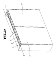
- the Fig. 21 shows similar to the Fig. 14 a sliding door cabinet with two approximately identically designed sliding leaves 21, 21 ', which are fastened with an upper fitting to a top floor 22 of the body and with a lower fitting to a subfloor.
- the in the FIGS. 22 to 27 and 31 to 33 illustrated upper fitting has a rail 4, which forms a running rail, which is located at the front edge of the upper floor 22.
- a support profile 33 forming profile rail.
- the running rail 4 has a guide rib on which a plurality of rollers 18 of a carriage 1 can roll.
- the carriage 1 has a guide profile 19 and at the other end of the guide profile 19 further rollers 31, 31 ', with which the carriage 1 is supported on two legs of the support profile 33.
- the two rollers 31, 31 ' extend in a C-shaped opening.
- the profile rib of the running rail 4, on which the roller 18 runs, is located in a U-profile.
- a roller 18 ' is supported on the tread rib opposite profile leg.
- the running rail 4 is formed by a profile body, which is mounted along the front peripheral edge of the topsoil, resting on the topsoil.
- the running rail 4 has a plurality of horizontal webs, which form the running rail 4 a high bending stiffness.
- the profile forming the running rail 4 forms a hollow chamber 40. This prevents that bends due to the weight of the sliding sash of the topsoil.
- the track 4 also has an upwardly projecting from the top floor 22 web 30.
- On the two web walls run horizontal rollers 29, which serve to stabilize. These stabilizing rollers 29 are located below the guide profile 19th
- a carriage 2 is mounted displaceably transversely to the direction of extension of the running rail 4 and the support section 3.
- rollers 28 which are mounted as guide rollers on a guide block 20 of the carriage 2 and can roll on profile webs of the guide profile 19.
- the carriage 2 has a horizontal plate which forms a mounting bracket 48 to which the rear broad side of the sliding leaf 21 is attached.
- the upper side of the mounting bracket 48 has a swept by a control lever 5 slot 27.
- the pivot bearing 9, by which the control lever 5 is pivotable in a horizontal plane, is assigned to the carriage 1 in a stationary manner.
- the control lever 5 has two shorter drive arms 7, 8 and at least twice as long a drive arm 6.
- the drive arm 8 is formed by a cam which protrudes from the output arm 6.
- the drive arm 7 protrudes from the pivot bearing 9 approximately at right angles to the output arm 6.
- the stop element 12 is a tongue-like stop carrier, which is fastened by means of fastening screws on the support section 33 and projects over the base plate of the carriage 2.
- the attachment side of the stop member 12 opposite free end of the stop carrier 12 forms a stop 14 which is formed as a sloping edge and which cooperates with the drive arm 7.
- the free end of the stop carrier 12 forms a control cam 13, which cooperates with a counter-control cam of the drive arm 8.
- An angular securing element 26 is provided.
- the securing element 26 is attached to the carriage 1 transversely to the direction of displacement of the carriage 2.
- the displacement direction of the securing element 26 is thus parallel to the direction of displacement of the carriage 1 along the running rail 4.
- a parallel to the direction of displacement of the securing element 26 extending leg has a longitudinal slot 38, engage by the fastening screws with which the securing element 26 is attached to the carriage 1.
- a tension spring 37 is a transverse to the direction of displacement of the securing element 26 extending leg against the carriage 2 is applied.
- the end of this leg forms a support shoulder 35.
- the securing element 26 also forms a stop cam 34, which cooperates with the stop element 12.
- the carriage 1 has two mutually parallel guide profiles 19. At one fixed end of the tension spring 37 is attached.
- the other guide profile 19 carries the securing element 26.
- Both guide profiles 19 each have stabilizing rollers 29.
- the two guide profiles 19 are connected to each other by means of roller carriers 17 which carry the rollers 18, 18 '. Further roller carriers carry the rollers 31.
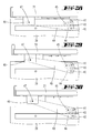
- the guide device fastened to the underbody 39 has a guide rail with a guide web 43.
- a guide lever 40 is articulated about an axis of rotation 47 at a mounting bracket 46, which is fastened to the rear broad side of the sliding leaf 21.
- the guide lever 40 carries at its free end two guide rollers 41, 42 which can roll 43 at the two sides facing away broad sides of the guide web.
- On the guide lever 40 also sits a control roller 45, which lies in the closed position of the sliding leaf 41 in front of a web edge 44 of the web 43.
- the web edge 44 is formed as a slope. In the open position ( FIG. 30 ) rolls the control roller 45 over a broad side of the web 43 and thus prevents pivoting back of the guide lever 40 in the in Fig. 28 illustrated closed position.
- the functionality of the fitting is the following:
- the sliding sash has a total of about 10 mm on the sliding sash 21 'to move, but a total of about 36 mm away from the body 22.
- the drive arm 8 Upon a return displacement of the sliding leaf 21 from the open position in the direction of the closed position, the drive arm 8 passes the free end of the stop element 12 until the drive arm 7 abuts against the stop 14.
- the stop cam 34 has entered against a peripheral edge of the stop element 12, so that the securing element 26 is displaced relative to the carriage 1, wherein the spring 37 is tensioned.
- the support shoulder 35 is displaced from the area of action of the peripheral edge 36.
- the base plate of the carriage 2 has a slot 27 through which engages the axis of the pivot bearing 9.
- the control lever 5 derives from a displacement movement at least twice as large offset movement transversely to the displacement direction.
- the mutually facing narrow edges of the sliding sash 21, 21 'need not be beveled, so that when moving the sliding sash moving past the non-moving sliding sash can pass.
- the narrow edges can be made blunt with the dimensioning according to the invention be and yet be arranged relatively close to each other, so that the gap width of the gap between the two sliding leaves is minimized in the closed position.
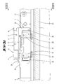
- FIGS. 34 to 37 show an alternative of a lower guide.
- a two webs 43, 43 ' having profiled rail is mounted on the underside of the lower floor 39.
- the two webs 43, 43 ' which run parallel to the front edge of the subfloor 39, form with their intermediate space a guide channel for a guide roller 41 and a control roller 45.
- the control roller 45 and the guide roller 41 are disposed at both ends of a guide lever 40.
- the guide lever 40 is connected to the rotation axis 47, which coincides with the axis of rotation of the control roller 45, at a fixedly connected to the sliding panel 21 mounting bracket 46.
- a tension spring 52 engages, which exerts a torque on the guide lever 40.
- the guide roller 41 sits.
- the guide roller 41 In the closed position of the sash, which in the Figures 34 and 36 is shown, the guide roller 41 is located in a straight-line section of between the webs 43, 43 'arranged channel.
- the beginning of the channel is formed by a rearwardly projecting from the front edge of the subfloor pocket 52.
- the control roller 45 In the closed position, the control roller 45 is located in the end portion of the pocket 52, so that the sliding wing 21 rests its position approximated to the carcass.
Landscapes
- Engineering & Computer Science (AREA)
- Mechanical Engineering (AREA)
- Support Devices For Sliding Doors (AREA)
- Power-Operated Mechanisms For Wings (AREA)
- Wing Frames And Configurations (AREA)
Applications Claiming Priority (1)
| Application Number | Priority Date | Filing Date | Title |
|---|---|---|---|
| DE102011050604A DE102011050604A1 (de) | 2011-05-24 | 2011-05-24 | Schiebetürbeschlag |
Publications (3)
| Publication Number | Publication Date |
|---|---|
| EP2527575A2 true EP2527575A2 (fr) | 2012-11-28 |
| EP2527575A3 EP2527575A3 (fr) | 2014-06-18 |
| EP2527575B1 EP2527575B1 (fr) | 2015-12-30 |
Family
ID=46148683
Family Applications (1)
| Application Number | Title | Priority Date | Filing Date |
|---|---|---|---|
| EP12169204.0A Not-in-force EP2527575B1 (fr) | 2011-05-24 | 2012-05-24 | Ferrure de porte coulissante |
Country Status (2)
| Country | Link |
|---|---|
| EP (1) | EP2527575B1 (fr) |
| DE (1) | DE102011050604A1 (fr) |
Cited By (1)
| Publication number | Priority date | Publication date | Assignee | Title |
|---|---|---|---|---|
| EP3088646A1 (fr) * | 2015-04-27 | 2016-11-02 | Eku Ag | Dispositif de guidage pour une porte coulissante |
Families Citing this family (1)
| Publication number | Priority date | Publication date | Assignee | Title |
|---|---|---|---|---|
| DE102015105982A1 (de) | 2015-04-20 | 2016-10-20 | Hettich-Heinze Gmbh & Co. Kg | Beschlag für eine Schiebetür und Verfahren zur Montage eines Führungsbeschlages |
Citations (3)
| Publication number | Priority date | Publication date | Assignee | Title |
|---|---|---|---|---|
| EP0195880A2 (fr) | 1985-03-25 | 1986-10-01 | CAIMI EXPORT S.p.A. | Structure de porte coulissante |
| DE3716876C2 (fr) | 1987-05-20 | 1990-09-06 | Huwil-Werke Gmbh Moebelschloss- Und Beschlagfabriken, 5207 Ruppichteroth, De | |
| DE102010016040A1 (de) | 2010-02-05 | 2011-08-11 | Weber & Co. GmbH KG, 42551 | Motorbetriebener Beschlag für einen Schiebetürschrank |
Family Cites Families (4)
| Publication number | Priority date | Publication date | Assignee | Title |
|---|---|---|---|---|
| JPS55160078A (en) | 1979-05-25 | 1980-12-12 | Fuji Photo Film Co Ltd | Fluorescent substance and preparation of the same |
| DE8913893U1 (de) * | 1989-11-25 | 1991-03-21 | Dictator Technik Dr. Wolfram Schneider & Co Verwaltungs- und Beteiligungsgesellschaft, 86356 Neusäß | Schließvorrichtung für Türen, Tore, Fenster, Klappen o.dgl. |
| AT406498B (de) * | 1998-11-10 | 2000-05-25 | Pohl Metalltechnik Gmbh | Schiebetüre |
| ITBL20030004A1 (it) * | 2003-04-09 | 2004-10-10 | Bortoluzzi Mobili S P A Ora Borto Luzzi Mobili S | Porte scorrevoli con guida a camma per chiusura complanare, |
-
2011
- 2011-05-24 DE DE102011050604A patent/DE102011050604A1/de not_active Ceased
-
2012
- 2012-05-24 EP EP12169204.0A patent/EP2527575B1/fr not_active Not-in-force
Patent Citations (3)
| Publication number | Priority date | Publication date | Assignee | Title |
|---|---|---|---|---|
| EP0195880A2 (fr) | 1985-03-25 | 1986-10-01 | CAIMI EXPORT S.p.A. | Structure de porte coulissante |
| DE3716876C2 (fr) | 1987-05-20 | 1990-09-06 | Huwil-Werke Gmbh Moebelschloss- Und Beschlagfabriken, 5207 Ruppichteroth, De | |
| DE102010016040A1 (de) | 2010-02-05 | 2011-08-11 | Weber & Co. GmbH KG, 42551 | Motorbetriebener Beschlag für einen Schiebetürschrank |
Cited By (2)
| Publication number | Priority date | Publication date | Assignee | Title |
|---|---|---|---|---|
| EP3088646A1 (fr) * | 2015-04-27 | 2016-11-02 | Eku Ag | Dispositif de guidage pour une porte coulissante |
| US10000962B2 (en) | 2015-04-27 | 2018-06-19 | Eku Ag | Guiding device for a sliding door |
Also Published As
| Publication number | Publication date |
|---|---|
| EP2527575A3 (fr) | 2014-06-18 |
| DE102011050604A1 (de) | 2012-11-29 |
| EP2527575B1 (fr) | 2015-12-30 |
Similar Documents
| Publication | Publication Date | Title |
|---|---|---|
| EP3926136B1 (fr) | Système de guidage pour pièces de meuble | |
| DE202008018448U1 (de) | Parallel abstellbarer Beschlag für einen Schiebeflügel eines Fensters oder einer Tür | |
| EP1040979B1 (fr) | Porte coulissante et pivotante pour véhicules, notamment véhicules de transport urbain de personnes | |
| EP3969703A1 (fr) | Système de guidage pour guider au moins un battant de porte | |
| EP2799651B1 (fr) | Ferrure de porte coulissante pour meuble | |
| DE102007012153A1 (de) | Führungsschiene eines Türschließ-oder Türantriebssystems | |
| WO2009115140A1 (fr) | Ferrure pour fenêtres coulissantes et portes coulissantes à coulissement horizontal | |
| DE102013104420A1 (de) | Führungsanordnung einer Schiebetür, Schiebetür und Möbel | |
| AT524557B1 (de) | Führungssystem zur Führung wenigstens eines Türflügels relativ zu einem Möbelkorpus | |
| EP2672045B1 (fr) | Agencement de guidage d'une porte coulissante d'un meuble à porte coulissante | |
| EP2165868B1 (fr) | Système de porte coulissante pivotante | |
| EP1816298B1 (fr) | Volet repliable coulissante | |
| WO2015003872A1 (fr) | Ferrure pour une fenêtre, une porte ou analogue comportant un vantail basculant ou coulissant | |
| EP2527575B1 (fr) | Ferrure de porte coulissante | |
| EP3088647B1 (fr) | Système à rails pour un dispositif de guidage | |
| EP4083363A1 (fr) | Dispositif coulissant pour porte coulissante, agencement et dispositif d'entraînement | |
| EP0763643A1 (fr) | Ferrure pour un battant d'une fenêtre, porte ou similaire, battant qui est déplaçable vers un deuxième plan parallèle et pouvant coulisser horizontalement à partir de cette position | |
| EP2837763B1 (fr) | Butée de porte coulissante et mobilier | |
| DE102012213782B4 (de) | Verlagerungsanordnung zur Verlagerung eines Schiebeflügels eines Fensters, einer Tür oder dergleichen relativ zu einer festen Einfassung mit einem flügelseitigen und einem einfassungsseitigen Steuerelement | |
| EP2071110B1 (fr) | Dispositif de guidage et de verrouillage d'un système basculant coulissant | |
| DE202005012828U1 (de) | Vorrichtung zum Verankern einer Sitzeinrichtung an einem Fahrzeugboden | |
| CH622854A5 (en) | Setting-out device on wings or the like of windows or doors | |
| DE202016002166U1 (de) | Beschlaganordnung | |
| DE102012015467A1 (de) | Vorrichtung zum Führen von zumindest zwei Schiebetürelementen | |
| DE3150669A1 (de) | "schliessfolgeregler fuer eine zweiflueglige tuer" |
Legal Events
| Date | Code | Title | Description |
|---|---|---|---|
| PUAI | Public reference made under article 153(3) epc to a published international application that has entered the european phase |
Free format text: ORIGINAL CODE: 0009012 |
|
| AK | Designated contracting states |
Kind code of ref document: A2 Designated state(s): AL AT BE BG CH CY CZ DE DK EE ES FI FR GB GR HR HU IE IS IT LI LT LU LV MC MK MT NL NO PL PT RO RS SE SI SK SM TR |
|
| AX | Request for extension of the european patent |
Extension state: BA ME |
|
| PUAL | Search report despatched |
Free format text: ORIGINAL CODE: 0009013 |
|
| AK | Designated contracting states |
Kind code of ref document: A3 Designated state(s): AL AT BE BG CH CY CZ DE DK EE ES FI FR GB GR HR HU IE IS IT LI LT LU LV MC MK MT NL NO PL PT RO RS SE SI SK SM TR |
|
| AX | Request for extension of the european patent |
Extension state: BA ME |
|
| RIC1 | Information provided on ipc code assigned before grant |
Ipc: E05D 15/10 20060101AFI20140514BHEP |
|
| 17P | Request for examination filed |
Effective date: 20140716 |
|
| RBV | Designated contracting states (corrected) |
Designated state(s): AL AT BE BG CH CY CZ DE DK EE ES FI FR GB GR HR HU IE IS IT LI LT LU LV MC MK MT NL NO PL PT RO RS SE SI SK SM TR |
|
| GRAP | Despatch of communication of intention to grant a patent |
Free format text: ORIGINAL CODE: EPIDOSNIGR1 |
|
| INTG | Intention to grant announced |
Effective date: 20150720 |
|
| GRAS | Grant fee paid |
Free format text: ORIGINAL CODE: EPIDOSNIGR3 |
|
| GRAA | (expected) grant |
Free format text: ORIGINAL CODE: 0009210 |
|
| AK | Designated contracting states |
Kind code of ref document: B1 Designated state(s): AL AT BE BG CH CY CZ DE DK EE ES FI FR GB GR HR HU IE IS IT LI LT LU LV MC MK MT NL NO PL PT RO RS SE SI SK SM TR |
|
| REG | Reference to a national code |
Ref country code: GB Ref legal event code: FG4D Free format text: NOT ENGLISH |
|
| REG | Reference to a national code |
Ref country code: CH Ref legal event code: EP |
|
| REG | Reference to a national code |
Ref country code: AT Ref legal event code: REF Ref document number: 767578 Country of ref document: AT Kind code of ref document: T Effective date: 20160115 |
|
| REG | Reference to a national code |
Ref country code: IE Ref legal event code: FG4D Free format text: LANGUAGE OF EP DOCUMENT: GERMAN |
|
| REG | Reference to a national code |
Ref country code: DE Ref legal event code: R096 Ref document number: 502012005568 Country of ref document: DE |
|
| REG | Reference to a national code |
Ref country code: LT Ref legal event code: MG4D |
|
| PG25 | Lapsed in a contracting state [announced via postgrant information from national office to epo] |
Ref country code: LT Free format text: LAPSE BECAUSE OF FAILURE TO SUBMIT A TRANSLATION OF THE DESCRIPTION OR TO PAY THE FEE WITHIN THE PRESCRIBED TIME-LIMIT Effective date: 20151230 Ref country code: HR Free format text: LAPSE BECAUSE OF FAILURE TO SUBMIT A TRANSLATION OF THE DESCRIPTION OR TO PAY THE FEE WITHIN THE PRESCRIBED TIME-LIMIT Effective date: 20151230 Ref country code: NO Free format text: LAPSE BECAUSE OF FAILURE TO SUBMIT A TRANSLATION OF THE DESCRIPTION OR TO PAY THE FEE WITHIN THE PRESCRIBED TIME-LIMIT Effective date: 20160330 |
|
| REG | Reference to a national code |
Ref country code: NL Ref legal event code: MP Effective date: 20151230 |
|
| PG25 | Lapsed in a contracting state [announced via postgrant information from national office to epo] |
Ref country code: RS Free format text: LAPSE BECAUSE OF FAILURE TO SUBMIT A TRANSLATION OF THE DESCRIPTION OR TO PAY THE FEE WITHIN THE PRESCRIBED TIME-LIMIT Effective date: 20151230 Ref country code: FI Free format text: LAPSE BECAUSE OF FAILURE TO SUBMIT A TRANSLATION OF THE DESCRIPTION OR TO PAY THE FEE WITHIN THE PRESCRIBED TIME-LIMIT Effective date: 20151230 Ref country code: SE Free format text: LAPSE BECAUSE OF FAILURE TO SUBMIT A TRANSLATION OF THE DESCRIPTION OR TO PAY THE FEE WITHIN THE PRESCRIBED TIME-LIMIT Effective date: 20151230 Ref country code: GR Free format text: LAPSE BECAUSE OF FAILURE TO SUBMIT A TRANSLATION OF THE DESCRIPTION OR TO PAY THE FEE WITHIN THE PRESCRIBED TIME-LIMIT Effective date: 20160331 Ref country code: LV Free format text: LAPSE BECAUSE OF FAILURE TO SUBMIT A TRANSLATION OF THE DESCRIPTION OR TO PAY THE FEE WITHIN THE PRESCRIBED TIME-LIMIT Effective date: 20151230 |
|
| PG25 | Lapsed in a contracting state [announced via postgrant information from national office to epo] |
Ref country code: NL Free format text: LAPSE BECAUSE OF FAILURE TO SUBMIT A TRANSLATION OF THE DESCRIPTION OR TO PAY THE FEE WITHIN THE PRESCRIBED TIME-LIMIT Effective date: 20151230 |
|
| PG25 | Lapsed in a contracting state [announced via postgrant information from national office to epo] |
Ref country code: ES Free format text: LAPSE BECAUSE OF FAILURE TO SUBMIT A TRANSLATION OF THE DESCRIPTION OR TO PAY THE FEE WITHIN THE PRESCRIBED TIME-LIMIT Effective date: 20151230 Ref country code: CZ Free format text: LAPSE BECAUSE OF FAILURE TO SUBMIT A TRANSLATION OF THE DESCRIPTION OR TO PAY THE FEE WITHIN THE PRESCRIBED TIME-LIMIT Effective date: 20151230 |
|
| PG25 | Lapsed in a contracting state [announced via postgrant information from national office to epo] |
Ref country code: PL Free format text: LAPSE BECAUSE OF FAILURE TO SUBMIT A TRANSLATION OF THE DESCRIPTION OR TO PAY THE FEE WITHIN THE PRESCRIBED TIME-LIMIT Effective date: 20151230 Ref country code: SK Free format text: LAPSE BECAUSE OF FAILURE TO SUBMIT A TRANSLATION OF THE DESCRIPTION OR TO PAY THE FEE WITHIN THE PRESCRIBED TIME-LIMIT Effective date: 20151230 Ref country code: PT Free format text: LAPSE BECAUSE OF FAILURE TO SUBMIT A TRANSLATION OF THE DESCRIPTION OR TO PAY THE FEE WITHIN THE PRESCRIBED TIME-LIMIT Effective date: 20160502 Ref country code: BE Free format text: LAPSE BECAUSE OF NON-PAYMENT OF DUE FEES Effective date: 20160531 Ref country code: IS Free format text: LAPSE BECAUSE OF FAILURE TO SUBMIT A TRANSLATION OF THE DESCRIPTION OR TO PAY THE FEE WITHIN THE PRESCRIBED TIME-LIMIT Effective date: 20160430 Ref country code: EE Free format text: LAPSE BECAUSE OF FAILURE TO SUBMIT A TRANSLATION OF THE DESCRIPTION OR TO PAY THE FEE WITHIN THE PRESCRIBED TIME-LIMIT Effective date: 20151230 Ref country code: RO Free format text: LAPSE BECAUSE OF FAILURE TO SUBMIT A TRANSLATION OF THE DESCRIPTION OR TO PAY THE FEE WITHIN THE PRESCRIBED TIME-LIMIT Effective date: 20151230 Ref country code: SM Free format text: LAPSE BECAUSE OF FAILURE TO SUBMIT A TRANSLATION OF THE DESCRIPTION OR TO PAY THE FEE WITHIN THE PRESCRIBED TIME-LIMIT Effective date: 20151230 |
|
| REG | Reference to a national code |
Ref country code: DE Ref legal event code: R097 Ref document number: 502012005568 Country of ref document: DE |
|
| PG25 | Lapsed in a contracting state [announced via postgrant information from national office to epo] |
Ref country code: DK Free format text: LAPSE BECAUSE OF FAILURE TO SUBMIT A TRANSLATION OF THE DESCRIPTION OR TO PAY THE FEE WITHIN THE PRESCRIBED TIME-LIMIT Effective date: 20151230 |
|
| PLBE | No opposition filed within time limit |
Free format text: ORIGINAL CODE: 0009261 |
|
| STAA | Information on the status of an ep patent application or granted ep patent |
Free format text: STATUS: NO OPPOSITION FILED WITHIN TIME LIMIT |
|
| 26N | No opposition filed |
Effective date: 20161003 |
|
| PG25 | Lapsed in a contracting state [announced via postgrant information from national office to epo] |
Ref country code: LU Free format text: LAPSE BECAUSE OF FAILURE TO SUBMIT A TRANSLATION OF THE DESCRIPTION OR TO PAY THE FEE WITHIN THE PRESCRIBED TIME-LIMIT Effective date: 20160524 |
|
| REG | Reference to a national code |
Ref country code: CH Ref legal event code: PL |
|
| REG | Reference to a national code |
Ref country code: DE Ref legal event code: R082 Ref document number: 502012005568 Country of ref document: DE Representative=s name: KOHLER SCHMID MOEBUS PATENTANWAELTE PARTNERSCH, DE Ref country code: DE Ref legal event code: R081 Ref document number: 502012005568 Country of ref document: DE Owner name: SLIDING COMPETENCE CENTER KFT., HU Free format text: FORMER OWNER: WEBER & CO. GMBH KG, 42551 VELBERT, DE |
|
| GBPC | Gb: european patent ceased through non-payment of renewal fee |
Effective date: 20160524 |
|
| PG25 | Lapsed in a contracting state [announced via postgrant information from national office to epo] |
Ref country code: LI Free format text: LAPSE BECAUSE OF NON-PAYMENT OF DUE FEES Effective date: 20160531 Ref country code: CH Free format text: LAPSE BECAUSE OF NON-PAYMENT OF DUE FEES Effective date: 20160531 |
|
| REG | Reference to a national code |
Ref country code: IE Ref legal event code: MM4A |
|
| PG25 | Lapsed in a contracting state [announced via postgrant information from national office to epo] |
Ref country code: SI Free format text: LAPSE BECAUSE OF FAILURE TO SUBMIT A TRANSLATION OF THE DESCRIPTION OR TO PAY THE FEE WITHIN THE PRESCRIBED TIME-LIMIT Effective date: 20151230 |
|
| REG | Reference to a national code |
Ref country code: FR Ref legal event code: ST Effective date: 20170131 |
|
| PG25 | Lapsed in a contracting state [announced via postgrant information from national office to epo] |
Ref country code: FR Free format text: LAPSE BECAUSE OF NON-PAYMENT OF DUE FEES Effective date: 20160531 |
|
| PG25 | Lapsed in a contracting state [announced via postgrant information from national office to epo] |
Ref country code: GB Free format text: LAPSE BECAUSE OF NON-PAYMENT OF DUE FEES Effective date: 20160524 Ref country code: IE Free format text: LAPSE BECAUSE OF NON-PAYMENT OF DUE FEES Effective date: 20160524 |
|
| PG25 | Lapsed in a contracting state [announced via postgrant information from national office to epo] |
Ref country code: HU Free format text: LAPSE BECAUSE OF FAILURE TO SUBMIT A TRANSLATION OF THE DESCRIPTION OR TO PAY THE FEE WITHIN THE PRESCRIBED TIME-LIMIT; INVALID AB INITIO Effective date: 20120524 Ref country code: CY Free format text: LAPSE BECAUSE OF FAILURE TO SUBMIT A TRANSLATION OF THE DESCRIPTION OR TO PAY THE FEE WITHIN THE PRESCRIBED TIME-LIMIT Effective date: 20151230 |
|
| PG25 | Lapsed in a contracting state [announced via postgrant information from national office to epo] |
Ref country code: MK Free format text: LAPSE BECAUSE OF FAILURE TO SUBMIT A TRANSLATION OF THE DESCRIPTION OR TO PAY THE FEE WITHIN THE PRESCRIBED TIME-LIMIT Effective date: 20151230 Ref country code: MT Free format text: LAPSE BECAUSE OF FAILURE TO SUBMIT A TRANSLATION OF THE DESCRIPTION OR TO PAY THE FEE WITHIN THE PRESCRIBED TIME-LIMIT Effective date: 20151230 Ref country code: MC Free format text: LAPSE BECAUSE OF FAILURE TO SUBMIT A TRANSLATION OF THE DESCRIPTION OR TO PAY THE FEE WITHIN THE PRESCRIBED TIME-LIMIT Effective date: 20151230 Ref country code: TR Free format text: LAPSE BECAUSE OF FAILURE TO SUBMIT A TRANSLATION OF THE DESCRIPTION OR TO PAY THE FEE WITHIN THE PRESCRIBED TIME-LIMIT Effective date: 20151230 |
|
| REG | Reference to a national code |
Ref country code: AT Ref legal event code: MM01 Ref document number: 767578 Country of ref document: AT Kind code of ref document: T Effective date: 20170524 |
|
| PG25 | Lapsed in a contracting state [announced via postgrant information from national office to epo] |
Ref country code: BG Free format text: LAPSE BECAUSE OF FAILURE TO SUBMIT A TRANSLATION OF THE DESCRIPTION OR TO PAY THE FEE WITHIN THE PRESCRIBED TIME-LIMIT Effective date: 20151230 |
|
| PG25 | Lapsed in a contracting state [announced via postgrant information from national office to epo] |
Ref country code: AT Free format text: LAPSE BECAUSE OF NON-PAYMENT OF DUE FEES Effective date: 20170524 |
|
| PG25 | Lapsed in a contracting state [announced via postgrant information from national office to epo] |
Ref country code: AL Free format text: LAPSE BECAUSE OF FAILURE TO SUBMIT A TRANSLATION OF THE DESCRIPTION OR TO PAY THE FEE WITHIN THE PRESCRIBED TIME-LIMIT Effective date: 20151230 |
|
| PGFP | Annual fee paid to national office [announced via postgrant information from national office to epo] |
Ref country code: DE Payment date: 20210520 Year of fee payment: 10 Ref country code: IT Payment date: 20210531 Year of fee payment: 10 |
|
| REG | Reference to a national code |
Ref country code: DE Ref legal event code: R119 Ref document number: 502012005568 Country of ref document: DE |
|
| PG25 | Lapsed in a contracting state [announced via postgrant information from national office to epo] |
Ref country code: DE Free format text: LAPSE BECAUSE OF NON-PAYMENT OF DUE FEES Effective date: 20221201 |
|
| PG25 | Lapsed in a contracting state [announced via postgrant information from national office to epo] |
Ref country code: IT Free format text: LAPSE BECAUSE OF NON-PAYMENT OF DUE FEES Effective date: 20220524 |
|
| P01 | Opt-out of the competence of the unified patent court (upc) registered |
Effective date: 20230630 |