EP2527657A2 - Procédés et systèmes pour conduits basse tension sans huile - Google Patents
Procédés et systèmes pour conduits basse tension sans huile Download PDFInfo
- Publication number
- EP2527657A2 EP2527657A2 EP12168635A EP12168635A EP2527657A2 EP 2527657 A2 EP2527657 A2 EP 2527657A2 EP 12168635 A EP12168635 A EP 12168635A EP 12168635 A EP12168635 A EP 12168635A EP 2527657 A2 EP2527657 A2 EP 2527657A2
- Authority
- EP
- European Patent Office
- Prior art keywords
- connector
- electrical cable
- outer sheath
- section
- internal core
- Prior art date
- Legal status (The legal status is an assumption and is not a legal conclusion. Google has not performed a legal analysis and makes no representation as to the accuracy of the status listed.)
- Withdrawn
Links
- 238000000034 method Methods 0.000 title claims abstract description 21
- 238000005219 brazing Methods 0.000 claims abstract description 16
- 238000003466 welding Methods 0.000 claims abstract description 15
- 239000012530 fluid Substances 0.000 claims description 6
- 239000012212 insulator Substances 0.000 claims description 5
- 238000005253 cladding Methods 0.000 description 6
- VNWKTOKETHGBQD-UHFFFAOYSA-N methane Chemical compound C VNWKTOKETHGBQD-UHFFFAOYSA-N 0.000 description 4
- 239000007789 gas Substances 0.000 description 3
- 239000003949 liquefied natural gas Substances 0.000 description 3
- 230000004048 modification Effects 0.000 description 3
- 238000012986 modification Methods 0.000 description 3
- 230000008569 process Effects 0.000 description 3
- 239000000126 substance Substances 0.000 description 3
- 229910000963 austenitic stainless steel Inorganic materials 0.000 description 2
- 230000005611 electricity Effects 0.000 description 2
- 229910052751 metal Inorganic materials 0.000 description 2
- 239000002184 metal Substances 0.000 description 2
- RYGMFSIKBFXOCR-UHFFFAOYSA-N Copper Chemical compound [Cu] RYGMFSIKBFXOCR-UHFFFAOYSA-N 0.000 description 1
- 229910000881 Cu alloy Inorganic materials 0.000 description 1
- RWSOTUBLDIXVET-UHFFFAOYSA-N Dihydrogen sulfide Chemical compound S RWSOTUBLDIXVET-UHFFFAOYSA-N 0.000 description 1
- FYYHWMGAXLPEAU-UHFFFAOYSA-N Magnesium Chemical compound [Mg] FYYHWMGAXLPEAU-UHFFFAOYSA-N 0.000 description 1
- 239000002253 acid Substances 0.000 description 1
- 238000005452 bending Methods 0.000 description 1
- 230000008859 change Effects 0.000 description 1
- 239000004020 conductor Substances 0.000 description 1
- 229910052802 copper Inorganic materials 0.000 description 1
- 239000010949 copper Substances 0.000 description 1
- 238000010292 electrical insulation Methods 0.000 description 1
- 238000010438 heat treatment Methods 0.000 description 1
- 238000009413 insulation Methods 0.000 description 1
- 230000003993 interaction Effects 0.000 description 1
- 229910052749 magnesium Inorganic materials 0.000 description 1
- 239000011777 magnesium Substances 0.000 description 1
- 238000004519 manufacturing process Methods 0.000 description 1
- 239000000463 material Substances 0.000 description 1
- 230000007246 mechanism Effects 0.000 description 1
- 239000003345 natural gas Substances 0.000 description 1
- TWNQGVIAIRXVLR-UHFFFAOYSA-N oxo(oxoalumanyloxy)alumane Chemical compound O=[Al]O[Al]=O TWNQGVIAIRXVLR-UHFFFAOYSA-N 0.000 description 1
- 239000000843 powder Substances 0.000 description 1
- 238000010248 power generation Methods 0.000 description 1
- 230000002028 premature Effects 0.000 description 1
- 238000011084 recovery Methods 0.000 description 1
- 230000009467 reduction Effects 0.000 description 1
- 229910001220 stainless steel Inorganic materials 0.000 description 1
- 239000010935 stainless steel Substances 0.000 description 1
Images




Classifications
-
- F—MECHANICAL ENGINEERING; LIGHTING; HEATING; WEAPONS; BLASTING
- F04—POSITIVE - DISPLACEMENT MACHINES FOR LIQUIDS; PUMPS FOR LIQUIDS OR ELASTIC FLUIDS
- F04D—NON-POSITIVE-DISPLACEMENT PUMPS
- F04D25/00—Pumping installations or systems
- F04D25/02—Units comprising pumps and their driving means
- F04D25/06—Units comprising pumps and their driving means the pump being electrically driven
- F04D25/0693—Details or arrangements of the wiring
-
- F—MECHANICAL ENGINEERING; LIGHTING; HEATING; WEAPONS; BLASTING
- F04—POSITIVE - DISPLACEMENT MACHINES FOR LIQUIDS; PUMPS FOR LIQUIDS OR ELASTIC FLUIDS
- F04D—NON-POSITIVE-DISPLACEMENT PUMPS
- F04D13/00—Pumping installations or systems
- F04D13/02—Units comprising pumps and their driving means
- F04D13/06—Units comprising pumps and their driving means the pump being electrically driven
- F04D13/08—Units comprising pumps and their driving means the pump being electrically driven for submerged use
- F04D13/10—Units comprising pumps and their driving means the pump being electrically driven for submerged use adapted for use in mining bore holes
-
- F—MECHANICAL ENGINEERING; LIGHTING; HEATING; WEAPONS; BLASTING
- F04—POSITIVE - DISPLACEMENT MACHINES FOR LIQUIDS; PUMPS FOR LIQUIDS OR ELASTIC FLUIDS
- F04D—NON-POSITIVE-DISPLACEMENT PUMPS
- F04D17/00—Radial-flow pumps, e.g. centrifugal pumps; Helico-centrifugal pumps
- F04D17/08—Centrifugal pumps
- F04D17/10—Centrifugal pumps for compressing or evacuating
- F04D17/12—Multi-stage pumps
- F04D17/122—Multi-stage pumps the individual rotor discs being, one for each stage, on a common shaft and axially spaced, e.g. conventional centrifugal multi- stage compressors
-
- F—MECHANICAL ENGINEERING; LIGHTING; HEATING; WEAPONS; BLASTING
- F04—POSITIVE - DISPLACEMENT MACHINES FOR LIQUIDS; PUMPS FOR LIQUIDS OR ELASTIC FLUIDS
- F04D—NON-POSITIVE-DISPLACEMENT PUMPS
- F04D29/00—Details, component parts, or accessories
- F04D29/05—Shafts or bearings, or assemblies thereof, specially adapted for elastic fluid pumps
- F04D29/056—Bearings
- F04D29/058—Bearings magnetic; electromagnetic
-
- H—ELECTRICITY
- H01—ELECTRIC ELEMENTS
- H01R—ELECTRICALLY-CONDUCTIVE CONNECTIONS; STRUCTURAL ASSOCIATIONS OF A PLURALITY OF MUTUALLY-INSULATED ELECTRICAL CONNECTING ELEMENTS; COUPLING DEVICES; CURRENT COLLECTORS
- H01R4/00—Electrically-conductive connections between two or more conductive members in direct contact, i.e. touching one another; Means for effecting or maintaining such contact; Electrically-conductive connections having two or more spaced connecting locations for conductors and using contact members penetrating insulation
- H01R4/02—Soldered or welded connections
- H01R4/023—Soldered or welded connections between cables or wires and terminals
-
- H—ELECTRICITY
- H01—ELECTRIC ELEMENTS
- H01R—ELECTRICALLY-CONDUCTIVE CONNECTIONS; STRUCTURAL ASSOCIATIONS OF A PLURALITY OF MUTUALLY-INSULATED ELECTRICAL CONNECTING ELEMENTS; COUPLING DEVICES; CURRENT COLLECTORS
- H01R4/00—Electrically-conductive connections between two or more conductive members in direct contact, i.e. touching one another; Means for effecting or maintaining such contact; Electrically-conductive connections having two or more spaced connecting locations for conductors and using contact members penetrating insulation
- H01R4/02—Soldered or welded connections
- H01R4/029—Welded connections
-
- Y—GENERAL TAGGING OF NEW TECHNOLOGICAL DEVELOPMENTS; GENERAL TAGGING OF CROSS-SECTIONAL TECHNOLOGIES SPANNING OVER SEVERAL SECTIONS OF THE IPC; TECHNICAL SUBJECTS COVERED BY FORMER USPC CROSS-REFERENCE ART COLLECTIONS [XRACs] AND DIGESTS
- Y10—TECHNICAL SUBJECTS COVERED BY FORMER USPC
- Y10T—TECHNICAL SUBJECTS COVERED BY FORMER US CLASSIFICATION
- Y10T29/00—Metal working
- Y10T29/49—Method of mechanical manufacture
- Y10T29/49002—Electrical device making
- Y10T29/49117—Conductor or circuit manufacturing
Definitions
- the present invention relates generally to methods and systems and, more particularly, to mechanisms and techniques for electrically connecting various internal parts of a turbomachinery to an external connection.
- a turbomachine can be a compressor, expander, turbine, pump, etc. or a combination of them.
- the turbomachines are used in engines, turbines, power generation, cryogenic applications, oil and gas, petrochemical applications, etc.
- turbomachine often used in the industry includes a compressor driven by an electrical motor. Such a turbomachine may be employed, e.g., for recovering methane, natural gas, and/or liquefied natural gas (LNG). The recovery of such gasses would reduce emissions and reduce flare operations during the loading of LNG onto ships. Other uses of this kind of turbomachine are known in the art and not discussed here.
- LNG liquefied natural gas
- the turbomachine 2 includes an electrical motor 4 connected to a compressor 6.
- the connection between the two machine shafts can be achieved by a mechanical joint 8.
- the motor external casing 10 may be attached to the compressor external casing 12 by, for example, bolts 14.
- the compressor 6 may include one or more impellers 16 attached to a compressor shaft 18.
- the compressor shaft 18 is configured to rotate around a longitudinal axis X. The rotation of the compressor shaft 18 is enhanced by using magnetic bearings 20 and 22 at both ends of the compressor shaft 18.
- the magnetic bearings 20 and 22 need a supply of electrical power in order to function.
- the electrical power is supplied to the magnetic bearings 20 and 22 via cables 24 and 26.
- Cable 24 connects to the magnetic bearing 20 while cable 26 connects to the magnetic bearing 22.
- Cable 24 is provided with a head 28 that is configured to mate with a corresponding head 30 of an external electrical cable 32.
- Cable 26 connects in a similar way to an external cable 34.
- Cables 24 and 26 are exposed to the media that is processed by the compressor. This media may be corrosive and is likely to have a high pressure and temperature. Thus, specific precautions need to be taken for protecting the cables.
- Cables 24 and 26 may be attached to an internal wall of the compressor casing 12. The same is true for the motor 4, in which cables 36 and 38 connect magnetic bearings 40 of the motor 4 to an outside power source.
- cables 24 and 26 they are representative of conventional low voltage conduits for delivering electricity to the magnetic bearings 20 and 22. These conventional conduits are typically constructed using metallic conduits which contain electrical cables. These conduits are then filled with oil to provide both electrical insulation and to provide additional resistance to external pressures which often exist in the various working environments for the turbomachine 2.
- the electrical cables 24 and 26 can reside in metallic conduits which can be flexible or rigid.
- An example, as shown in Figure 2 of a flexible metallic conduit is a corrugated pipe 42 which has a small thickness of sheet metal, which may be a stainless steel. Low voltage electrical connections are typically attached to each end of the corrugated pipe by welding.
- the corrugated pipe is then typically surrounded by a bridle 44, an example of which is shown in Figure 3 , of metal that assists in protecting the corrugated pipe from damage during assembly and operation.
- a conventional rigid conduit is a rigid pipe which contains the electrical cables and also has an electrical connecter on each end of the pipe. These conventional electrical cables can generally operate in conditions of up to 125 °C and 140 bar. These conventional conduits have various considerations for use as will now be described.
- Oil filled corrugated pipes 42 typically need to support external pressure applied upon them while maintaining some flexibility. This tradeoff results in thin walls to reduce stress when bending, while attempting to provide support against externally applied pressure. Handling and fabrication of the oil filled corrugated pipes is also challenging due to the small wall thickness of these corrugated pipes as well as the need to be correctly filled so as to remove the presence of gas which may generate conduit restriction when under an external gas pressure. Also the thermal gradient needs to be considered since the oil expansion from heating can also generate undesirable mechanical stress on the corrugated pipe. Additionally, for flexible pipes which contain electrical cables, the environment within the turbomachine 2, e.g., an acid or sour gas presence, may also cause failure (or premature replacement requirements) for the thin walled, flexible, corrugated pipes 42.
- an acid or sour gas presence may also cause failure (or premature replacement requirements) for the thin walled, flexible, corrugated pipes 42.
- routing and assembly within the turbomachine 2 is generally not optimal due to the lack of flexibility of the pipes.
- the turbomachine includes: a compressor having a compressor shaft configured to rotate; first and second magnetic bearings provided at opposite ends of the compressor shaft and configured to support the compressor shaft; a motor having a motor shaft configured to be connected to the compressor shaft and a first electrical cable configured to connect the first magnetic bearing to a first external connection, wherein the first electrical cable has a first end, a second end, an internal core section and an outer sheath section with the internal core section and the outer sheath section extending from the first end to the second end.
- first connector configured to connect the first end of the first electrical cable to the first magnetic bearing, wherein the first connector is welded or brazed to the first end of the first electrical cable to both the internal core section and the outer sheath section; and a second connector configured to connect the second end of the first electrical cable to the first external connection, wherein the second connector is welded or brazed to the second end of the second electrical cable to both the internal core section and the outer sheath section.
- a method for electrically connecting magnetic bearings in a turbomachine to external connectors includes: welding or brazing a first connector to a first end of a first electrical cable, wherein the first connector is welded or brazed to both an internal core section and an outer sheath section of the first end of the first electrical cable; and welding or brazing a second connector to a second end of the first electrical cable, wherein the second connector is welded or brazed to both the internal core section and the outer sheath section of the second end of the first electrical cable.
- oil free electrical conduits can provide low voltage to magnetic bearings in turbomachines, e.g., compressor, expander, turbine, pump, etc. or a combination of them, in ways which avoid or minimize some or all of the issues described for conventional electrical conduits in the Background section. Additionally, some exemplary embodiments, can realize cost savings over conventional conduits by, for example, providing a longer working life at higher pressures and temperatures for the electrical conduits.
- the turbomachine 46 can have similarities to the turbomachine 2 shown in Figure 1 , except that, at a minimum, the conduits for providing the voltage to the magnetic bearings are different (as well as other inter-related parts as are described below) as compared to the conduits used in a conventional turbomachine 2.
- the turbomachine 46 includes an electrical motor 48 connected to a compressor 50.
- a compressor shaft 52 and a motor shaft 54 are connected and configured to rotate around a longitudinal axis X. The rotation of the compressor shaft 52 is enhanced by using magnetic bearings 56 and 58 at both ends of the compressor shaft 52.
- electrical power is supplied to the magnetic bearings 56 and 58 via electrical cables 60 and 62.
- Electrical cable 60 connects to the magnetic bearing 56 while electrical cable 62 connects to the magnetic bearing 58.
- Electrical cable 60 can be provided with a connector 64 on one end to mate with an external connection 66 and another connector 68 to mate with the magnetic bearing 56.
- Electrical cable 62 can be provided with a connector 70 on one end to mate with an external connection 72 and another connector 74 to mate with the magnetic bearing 58.
- These electric cables 60 and 62 are exposed to the media that is processed by the compressor 50, which may be corrosive, under a high pressure and/or at an elevated temperature, e.g., 500 °C and 220 bar (which may occur on a suction side of the turbomachine 46) or up to 700 bar (which may occur on a discharge side of a turbomachine 46).
- an elevated temperature e.g., 500 °C and 220 bar (which may occur on a suction side of the turbomachine 46) or up to 700 bar (which may occur on a discharge side of a turbomachine 46).
- the electrical cables 60 and 62, magnetic bearings 56 and 58, connectors 64 and 68, and methods of connection described herein could be used with other temperature and pressure combinations, i.e., it is expected that as higher pressures and temperatures are used in turbomachinery (temperatures over 500 °C and pressures over 700 bar) exemplary embodiments described herein can be generally scaled as needed for use in those environments.
- turbomachine 46 can also support exemplary embodiments which are described in more detail below.
- Modifications to turbomachine 46 can include having a compressor and a motor having a single, one-piece shaft (or rigidly connected shafts).
- a shared bearing can be used, leading to a configuration with a total of three magnetic bearings for this turbomachine.
- the quantity of magnetic bearings used can change and be significantly increased, e.g., 2 magnetic bearings per shaft per component of the turbomachine which uses a shaft in an environment which includes the process fluid.
- turbomachines can include more or fewer parts and components.
- a turbomachine can be described more generically which can still make use of exemplary embodiments described herein.
- a turbomachine can alternatively be described to include a rotor with a rotor shaft which rotates and includes magnetic bearings, electrical cables and connectors as described in exemplary embodiments described herein.
- the cladding 78 is the surrounded by an insulator 80, e.g., a magnesium or aluminum oxide power, which is then surrounded by an outer sheath 82, e.g., IN625 or an austenitic stainless steel.
- the insulator 80 prevents electrical leakage from the conductive core 76 to the outer sheath 82 while also providing support for use under high pressures allowing for little or no deformation of the electric cable 60.
- no internal oil fill (or other fluid fill) needs to be performed to these electrical cables 60 and 62.
- the diameter of the electrical cables 60 and 62 may be approximately 6 mm, with a length varying depending upon the size of the turbomachine 46 and how the electrical cables are routed within the turbomachine 46. Also it is possible to form out the electrical cables 60 and 62 before assembly by, for example, using tooling to fit and make the desired routing within the turbomachine 46. Additionally, electrical cables 60 and 62 may each represent a plurality of electrical cables for delivering the low voltage to the magnetic bearings 56 and 58.
- connectors 64, 68, 70 and 74 can be welded to each end of the electrical cables 60 and 62.
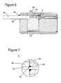
- An example of a connector 64, 68, 70 and 74 that can be welded or brazed to an end of an electrical cable 60 or 62 is now described with respect to Figures 6 and 7.
- Figure 6 shows the electrical cable 60 and the connector 64.
- Reference point 84 shows a position where the outer sheath 82 can be fully circumferential welded or brazed to the connector 64.
- Area A which shows an expanded view of a second weld location, is shown in an expanded view in Figure 7 .
- Figure 7 shows where the cladding 78 can be welded or brazed to a connector pin 88 of the connector 64 at reference point 86.
- a brazing powder should be selected which avoids or minimizes any negative interactions, e.g., undesirable thermal expansion or damage to the insulator 80, between the electrical cable 60 and the connector 64, as well as, between the various sections of the electrical cable 60.
- Similar methods for attaching a connector 68, 70 and 74 can be used for the other end of electrical cable 60, both ends of electrical cable 62 and other electrical cables if they are used.
- a plurality of electrical cables 60 with a similar shape can be used to supply a low voltage from the external connection 66 to the magnetic bearing 56 as shown in Figure 8 .
- each connector 64 and 66 can be attached to multiple electric cables 60.
- one or more belts 90 can be used to keep the electrical cables 60 generally together and to provide some dampening for them from the vibrations that can be generated when the turbomachine 46 is in operation.
- the electrical cables 60 can also be supported by and/or attached to the casing of the turbomachine 46 to further reduce the possibility of damage from vibrations.
- a plurality of conductive cores can reside within a single electrical cable as shown in Figure 9 .
- Figure 9 shows a single electric cable 98 with multiple conductive cores 92, an insulation section 94 and an outer sheath 96.
- the materials used for these sections are similar to those described above for a single conductive core in a single electrical cable.
- each conductive core 92 can be surrounded by a cladding.
- Figure 10 shows a routing of the electrical cable 60 from the magnetic bearing 56 to the external connection 66.
- a length for this routing can be, for example, one meter.
- other routings and lengths of the electrical cable 60 within the turbomachine 46 can be used as desired.
- exemplary embodiments described herein have generally described electrical cables providing low voltage to magnetic bearings in a compressor, which can be a part of the turbomachine, these examples are not to be considered limiting to only the compressor. Instead, these exemplary embodiments can also be applied to electric cables providing electricity to magnetic bearings in other components of turbomachines as desired.
- the method for electrically connecting magnetic bearings in a turbomachine to external connectors includes: a step 100 of welding or brazing a first connector to a first end of a first electrical cable, wherein the first connector is welded or brazed to both an internal core section and an outer sheath section of the first end of the first electrical cable and a step 102 of welding or brazing a second connector to a second end of the first electrical cable, wherein the second connector is welded or brazed to both the internal core section and the outer sheath section of the second end of the first electrical cable.
- the connectors 64, 68, 70 and 72 may be welded to the cladding 78 of the internal core section 76.
- various advantages can be provided in the environment of turbomachines.
- flexible electrical cables described herein can have better chemical properties for withstanding corrosive properties associated with various process fluids, as well as having better mechanical properties for operating at elevated temperatures and pressures then currently used electrical cables in conventional turbomachines.
- exemplary embodiments described herein can be used for other magnetic bearings which operate in a process fluid.
- the exemplary electrical cable 60 can have a smaller size and thickness with acceptable flexibility as compared with various conventional rigid pipe solutions.
- significant cost reductions can be realized by implementing exemplary embodiments described herein, e.g., a cost associated with the electrical cable 60 could be as much as twenty times less than the cost of similarly used conventional electrical cables in a turbomachine.
Landscapes
- Engineering & Computer Science (AREA)
- Mechanical Engineering (AREA)
- General Engineering & Computer Science (AREA)
- Physics & Mathematics (AREA)
- Electromagnetism (AREA)
- Mining & Mineral Resources (AREA)
- Structures Of Non-Positive Displacement Pumps (AREA)
- Magnetic Bearings And Hydrostatic Bearings (AREA)
- Motor Or Generator Frames (AREA)
- Gas Or Oil Filled Cable Accessories (AREA)
- Quick-Acting Or Multi-Walled Pipe Joints (AREA)
Applications Claiming Priority (1)
| Application Number | Priority Date | Filing Date | Title |
|---|---|---|---|
| IT000020A ITCO20110020A1 (it) | 2011-05-25 | 2011-05-25 | Metodi e sistemi per condotti a bassa tensione privi di olio |
Publications (2)
| Publication Number | Publication Date |
|---|---|
| EP2527657A2 true EP2527657A2 (fr) | 2012-11-28 |
| EP2527657A3 EP2527657A3 (fr) | 2016-06-29 |
Family
ID=44554905
Family Applications (1)
| Application Number | Title | Priority Date | Filing Date |
|---|---|---|---|
| EP12168635.6A Withdrawn EP2527657A3 (fr) | 2011-05-25 | 2012-05-21 | Procédés et systèmes pour conduits basse tension sans huile |
Country Status (6)
| Country | Link |
|---|---|
| US (1) | US8978243B2 (fr) |
| EP (1) | EP2527657A3 (fr) |
| JP (1) | JP2013007378A (fr) |
| CN (1) | CN102817645B (fr) |
| IT (1) | ITCO20110020A1 (fr) |
| RU (1) | RU2012121260A (fr) |
Families Citing this family (2)
| Publication number | Priority date | Publication date | Assignee | Title |
|---|---|---|---|---|
| CN109390103A (zh) * | 2018-11-08 | 2019-02-26 | 鑫国集团有限公司 | 一种无磁场铠装信号电缆 |
| CN109412353B (zh) * | 2018-12-05 | 2019-12-24 | 佛山市奥力博动力工程有限公司 | 一种用于发电机组中的引脚槽分段母线的接线连接装置 |
Family Cites Families (28)
| Publication number | Priority date | Publication date | Assignee | Title |
|---|---|---|---|---|
| US2808492A (en) | 1954-07-26 | 1957-10-01 | Gen Electric | Electric heating units and methods of making the same |
| GB2057781B (en) * | 1979-08-21 | 1983-04-13 | Standard Telephones Cables Ltd | Electrical connector assemblies |
| FR2503442A1 (fr) | 1981-04-07 | 1982-10-08 | Cables De Lyon Geoffroy Delore | Procede de fabrication de cables electriques a isolant mineral comprime et gaine metallique |
| FR2555352B1 (fr) | 1983-11-21 | 1987-02-20 | Thermocoax Cie | Cable blinde a isolant mineral et procede de fabrication permettant d'obtenir un tel cable |
| FR2575321B1 (fr) | 1984-12-21 | 1988-01-15 | Thermocoax Cie | Cable blinde a isolant mineral |
| FR2590980B1 (fr) | 1985-12-03 | 1988-08-05 | Thermocoax Cie | Thermocouple pour la mesure de temperatures elevees dans des milieux corrosifs |
| DE8716167U1 (de) * | 1987-12-08 | 1988-01-21 | Kabelmetal Electro Gmbh, 30179 Hannover | Hitzebeständige elektrische Leitung |
| DE8716166U1 (de) * | 1987-12-08 | 1988-01-21 | Kabelmetal Electro Gmbh, 30179 Hannover | Hitzebeständige elektrische Leitung |
| DE3842294A1 (de) * | 1988-12-13 | 1990-06-21 | Tkm Telekommunikation U Elektr | Anschlussstecker fuer ein hochfrequenzkabel |
| DE4037753A1 (de) * | 1990-11-28 | 1992-06-11 | Danfoss Flensburg Gmbh | Elektrische maschine |
| US5214243A (en) * | 1991-10-11 | 1993-05-25 | Endevco Corporation | High-temperature, low-noise coaxial cable assembly with high strength reinforcement braid |
| US5359491A (en) | 1991-11-27 | 1994-10-25 | U.S. Philips Corporation | Capacitive sensor comprising a conductive front surface for forming a capacitor plate, and a coaxial cable shielded by a mineral insulator |
| FI96459C (fi) * | 1994-07-12 | 1996-06-25 | Solitra Oy | Liitosjärjestely |
| SE9602079D0 (sv) | 1996-05-29 | 1996-05-29 | Asea Brown Boveri | Roterande elektriska maskiner med magnetkrets för hög spänning och ett förfarande för tillverkning av densamma |
| FR2750490B1 (fr) | 1996-06-26 | 1998-08-28 | Philips Electronics Nv | Dispositif du type capteur capacitif integre |
| JP2002134812A (ja) * | 2000-10-19 | 2002-05-10 | Ntn Corp | エキシマレーザ装置用還流ファンの構造 |
| DE20301679U1 (de) | 2003-02-04 | 2003-04-17 | Thermocoax GmbH, 22145 Stapelfeld | Thermoelement |
| ES2586658T3 (es) * | 2003-03-10 | 2016-10-18 | Thermodyn | Grupo compresor centrífugo |
| JP4166599B2 (ja) * | 2003-03-17 | 2008-10-15 | 株式会社フジクラ | コネクタ接続部品及びコネクタ接続構造 |
| DE10330862A1 (de) * | 2003-07-09 | 2005-01-27 | Nexans | Hochtemperaturbeständige elektrische Leitung |
| FR2861142B1 (fr) | 2003-10-16 | 2006-02-03 | Mecanique Magnetique Sa | Pompe a vide turbo moleculaire |
| DE202004015135U1 (de) | 2004-09-27 | 2004-11-25 | Thermocoax Gmbh | Tauchheizer für die Warmhaltung von Aluminiumschmelzen |
| JP2007162723A (ja) | 2005-12-09 | 2007-06-28 | Ntn Corp | モータ一体型磁気軸受装置 |
| BRPI0709128A2 (pt) * | 2006-03-24 | 2011-06-28 | Siemens Ag | unidade compressora |
| DE102007027711A1 (de) * | 2007-06-15 | 2008-12-18 | Pfeiffer Vacuum Gmbh | Verfahren zum Betreiben einer Anordnung mit Vakuumpumpe und Anordnung mit einer Vakuumpumpe |
| DE102008031994B4 (de) * | 2008-04-29 | 2011-07-07 | Siemens Aktiengesellschaft, 80333 | Fluidenergiemaschine |
| DE602009000573D1 (de) * | 2009-02-13 | 2011-02-24 | Alcatel Lucent | Herstellungsverfahren für eine Verbindung zwischen einem Koaxialkabel und einem Koaxialstecker und Koaxialkabel mit Koaxialsteckerabschluss |
| CN101707296A (zh) * | 2009-11-24 | 2010-05-12 | 贵州航天电器股份有限公司 | 一种端接电缆的连接器 |
-
2011
- 2011-05-25 IT IT000020A patent/ITCO20110020A1/it unknown
-
2012
- 2012-05-21 EP EP12168635.6A patent/EP2527657A3/fr not_active Withdrawn
- 2012-05-23 JP JP2012117210A patent/JP2013007378A/ja active Pending
- 2012-05-24 RU RU2012121260/06A patent/RU2012121260A/ru not_active Application Discontinuation
- 2012-05-25 US US13/480,563 patent/US8978243B2/en not_active Expired - Fee Related
- 2012-05-25 CN CN201210165695.XA patent/CN102817645B/zh not_active Expired - Fee Related
Non-Patent Citations (1)
| Title |
|---|
| None |
Also Published As
| Publication number | Publication date |
|---|---|
| EP2527657A3 (fr) | 2016-06-29 |
| US20120299412A1 (en) | 2012-11-29 |
| US8978243B2 (en) | 2015-03-17 |
| RU2012121260A (ru) | 2013-11-27 |
| JP2013007378A (ja) | 2013-01-10 |
| ITCO20110020A1 (it) | 2012-11-26 |
| CN102817645A (zh) | 2012-12-12 |
| CN102817645B (zh) | 2016-03-16 |
Similar Documents
| Publication | Publication Date | Title |
|---|---|---|
| US20210229269A1 (en) | Extension tool having a plurality of links | |
| US8978243B2 (en) | Methods and systems for oil free low voltage conduits | |
| EP2689515B1 (fr) | Cône élastique pour stator fermé hermétiquement, moteur correspondant et procédé de fabrication | |
| EP1867909B1 (fr) | Système de pénétration de tuyau | |
| US11208956B2 (en) | Fuel injectors and methods of making fuel injectors | |
| RU2596695C2 (ru) | Акселерометр | |
| EP2472069B1 (fr) | Conduit pour turbomachine et procédé | |
| EP3413442B1 (fr) | Pièce métallique creuse de stator de machine électrique tournante, machine électrique tournante et procédé de fabrication de pièce métallique creuse | |
| EP2469042B1 (fr) | Connexion électrique de turbomachine et procédé assosié | |
| EP2735836B1 (fr) | Échangeur de chaleur | |
| JP2017531129A (ja) | 背中合わせに2つのステージを配置してステージ間に環状の移送ダクトを備えた遠心ターボ機械 | |
| CN111015064A (zh) | 一种鹤管支撑同心装配工装及装配方法 |
Legal Events
| Date | Code | Title | Description |
|---|---|---|---|
| PUAI | Public reference made under article 153(3) epc to a published international application that has entered the european phase |
Free format text: ORIGINAL CODE: 0009012 |
|
| AK | Designated contracting states |
Kind code of ref document: A2 Designated state(s): AL AT BE BG CH CY CZ DE DK EE ES FI FR GB GR HR HU IE IS IT LI LT LU LV MC MK MT NL NO PL PT RO RS SE SI SK SM TR |
|
| AX | Request for extension of the european patent |
Extension state: BA ME |
|
| PUAL | Search report despatched |
Free format text: ORIGINAL CODE: 0009013 |
|
| AK | Designated contracting states |
Kind code of ref document: A3 Designated state(s): AL AT BE BG CH CY CZ DE DK EE ES FI FR GB GR HR HU IE IS IT LI LT LU LV MC MK MT NL NO PL PT RO RS SE SI SK SM TR |
|
| AX | Request for extension of the european patent |
Extension state: BA ME |
|
| RIC1 | Information provided on ipc code assigned before grant |
Ipc: F04D 25/06 20060101ALI20160525BHEP Ipc: H01B 7/29 20060101ALI20160525BHEP Ipc: F04D 13/10 20060101AFI20160525BHEP Ipc: H01R 9/05 20060101ALI20160525BHEP Ipc: H01R 4/02 20060101ALI20160525BHEP Ipc: F04D 29/058 20060101ALI20160525BHEP |
|
| STAA | Information on the status of an ep patent application or granted ep patent |
Free format text: STATUS: THE APPLICATION IS DEEMED TO BE WITHDRAWN |
|
| 18D | Application deemed to be withdrawn |
Effective date: 20161201 |