EP2527708A1 - Vorrichtung zur Inspektion von Pipelines und Pipeline-Inspektionsverfahren - Google Patents
Vorrichtung zur Inspektion von Pipelines und Pipeline-Inspektionsverfahren Download PDFInfo
- Publication number
- EP2527708A1 EP2527708A1 EP11167721A EP11167721A EP2527708A1 EP 2527708 A1 EP2527708 A1 EP 2527708A1 EP 11167721 A EP11167721 A EP 11167721A EP 11167721 A EP11167721 A EP 11167721A EP 2527708 A1 EP2527708 A1 EP 2527708A1
- Authority
- EP
- European Patent Office
- Prior art keywords
- sensor units
- inspection
- group
- sensor unit
- pipeline
- Prior art date
- Legal status (The legal status is an assumption and is not a legal conclusion. Google has not performed a legal analysis and makes no representation as to the accuracy of the status listed.)
- Withdrawn
Links
- 238000007689 inspection Methods 0.000 title claims abstract description 78
- 238000000034 method Methods 0.000 title claims description 13
- 238000011144 upstream manufacturing Methods 0.000 claims abstract description 28
- 239000000725 suspension Substances 0.000 claims description 18
- 239000000969 carrier Substances 0.000 claims description 3
- 238000003491 array Methods 0.000 description 4
- 238000011156 evaluation Methods 0.000 description 2
- 239000007788 liquid Substances 0.000 description 2
- 230000007547 defect Effects 0.000 description 1
- 238000010586 diagram Methods 0.000 description 1
- 230000009977 dual effect Effects 0.000 description 1
- 238000011065 in-situ storage Methods 0.000 description 1
- 238000012423 maintenance Methods 0.000 description 1
- 238000005096 rolling process Methods 0.000 description 1
Images

Classifications
-
- G—PHYSICS
- G01—MEASURING; TESTING
- G01N—INVESTIGATING OR ANALYSING MATERIALS BY DETERMINING THEIR CHEMICAL OR PHYSICAL PROPERTIES
- G01N29/00—Investigating or analysing materials by the use of ultrasonic, sonic or infrasonic waves; Visualisation of the interior of objects by transmitting ultrasonic or sonic waves through the object
- G01N29/22—Details, e.g. general constructional or apparatus details
- G01N29/26—Arrangements for orientation or scanning by relative movement of the head and the sensor
- G01N29/265—Arrangements for orientation or scanning by relative movement of the head and the sensor by moving the sensor relative to a stationary material
-
- F—MECHANICAL ENGINEERING; LIGHTING; HEATING; WEAPONS; BLASTING
- F16—ENGINEERING ELEMENTS AND UNITS; GENERAL MEASURES FOR PRODUCING AND MAINTAINING EFFECTIVE FUNCTIONING OF MACHINES OR INSTALLATIONS; THERMAL INSULATION IN GENERAL
- F16L—PIPES; JOINTS OR FITTINGS FOR PIPES; SUPPORTS FOR PIPES, CABLES OR PROTECTIVE TUBING; MEANS FOR THERMAL INSULATION IN GENERAL
- F16L55/00—Devices or appurtenances for use in, or in connection with, pipes or pipe systems
- F16L55/26—Pigs or moles, i.e. devices movable in a pipe or conduit with or without self-contained propulsion means
- F16L55/28—Constructional aspects
-
- F—MECHANICAL ENGINEERING; LIGHTING; HEATING; WEAPONS; BLASTING
- F16—ENGINEERING ELEMENTS AND UNITS; GENERAL MEASURES FOR PRODUCING AND MAINTAINING EFFECTIVE FUNCTIONING OF MACHINES OR INSTALLATIONS; THERMAL INSULATION IN GENERAL
- F16L—PIPES; JOINTS OR FITTINGS FOR PIPES; SUPPORTS FOR PIPES, CABLES OR PROTECTIVE TUBING; MEANS FOR THERMAL INSULATION IN GENERAL
- F16L2101/00—Uses or applications of pigs or moles
- F16L2101/30—Inspecting, measuring or testing
-
- G—PHYSICS
- G01—MEASURING; TESTING
- G01N—INVESTIGATING OR ANALYSING MATERIALS BY DETERMINING THEIR CHEMICAL OR PHYSICAL PROPERTIES
- G01N2291/00—Indexing codes associated with group G01N29/00
- G01N2291/10—Number of transducers
- G01N2291/106—Number of transducers one or more transducer arrays
-
- G—PHYSICS
- G01—MEASURING; TESTING
- G01N—INVESTIGATING OR ANALYSING MATERIALS BY DETERMINING THEIR CHEMICAL OR PHYSICAL PROPERTIES
- G01N2291/00—Indexing codes associated with group G01N29/00
- G01N2291/26—Scanned objects
- G01N2291/263—Surfaces
- G01N2291/2636—Surfaces cylindrical from inside
Definitions
- the present disclosure relates to a pipeline inspection apparatus and a method of pipeline inspection.
- Wall thickness and cracks in the wall of a liquid-filled pipeline can be measured or detected using ultrasonic sensors, wherein the liquid in the pipeline provides a couple medium for transferring ultrasonic waves from the ultrasonic sensors to the pipe wall.
- the ultrasonic sensors are mounted on a sensor carrier, which is intended to position the ultrasonic sensors adjacent the pipe wall, e.g. as a pig carries out an inspection run through a pipeline.
- the sensor carrier may consist of or include a skid, which is intended to run immediately adjacent or in contact with an inner surface of the pipe, with the sensors arranged at a stand off from the outer surface of the skid, in order to protect the sensors against wear or other damage from contact with the pipe.
- skids take one of two forms: a skid having a generally helical shape with respect to a longitudinal axis of the apparatus; or a straight skid which extends parallel with or at an angle of inclination to the longitudinal axis of the apparatus.
- the skids can not be adjusted and/or changed during an inspection run without physically stopping the apparatus at a location along the pipeline and carrying out maintenance in situ.
- the conventional skids are often unsuitable for use in inspecting a pipeline which has variations in bore diameter along its length.
- a given skid design is only suitable for a single diameter of pipe.
- the disclosure proposes an apparatus and method of pipeline inspection which overcomes or mitigates one or more of the above problems, or other disadvantages or problems associated with conventional apparatus and methods for inline inspection of pipelines using ultrasonic sensors.
- the disclosure further provides a method of pipeline inspection for a pipeline having a first section with a first bore diameter and a second section with a second bore diameter which is greater than the first bore diameter, said method including the step of:
- the disclosure provides an apparatus for pipeline inspection, the apparatus having a longitudinal axis and comprising a plurality of ultrasonic sensor units arranged for inspection of a pipe wall, each sensor unit including an array of ultrasonic sensors, wherein said plurality of sensor units defines two or more groups of sensor units, said groups of sensor units being axially offset from one another with respect to the longitudinal axis of the apparatus, the sensor units in each group being spaced circumferentially from one another, further wherein the sensor units are arranged out of phase, to provide inspection coverage for the circumferential spacing between the sensor units in said groups, so that the combined output from the groups of sensor units provides 360 degrees of inspection coverage.
- each array of ultrasonic sensors defines an arc of a circle extending in a circumferential direction with respect to a longitudinal axis of the apparatus.
- Each array of ultrasonic sensors may be mounted on a carrier and biased locally on said carrier in a radial direction with respect to a longitudinal axis of the apparatus.
- Each carrier is movable between a first radial position for a first bore diameter to a second radial position for a second bore diameter, e.g. greater than said first diameter.
- each array of ultrasonic sensors defines an inspection zone and the combined area of coverage for the inspections zones is at least enough to permit circumferential inspection of the internal circumference of a pipe when one or more of said carriers is in said second radial position.
- part of a pipeline inspection apparatus for in-line inspection of pipelines is indicated generally at 10.
- the apparatus 10 includes first and second sensor vessels 11A, 11B, which are coupled for movement together along a pipeline.
- vessel 11A would be the leading or upstream vessel, in use, with vessel 11B arranged downstream of vessel 11A.
- Each vessel 11A, 11B is provided with multiple ultrasonic sensor units 14, each of which is movably mounted in a manner described in more detail below.
- Each sensor unit 14 includes multiple ultrasonic sensors 16.
- the sensors 16 define an arcuate inspection array, which extends in a circumferential direction with respect to a longitudinal axis of the apparatus 10.
- the ultrasonic sensors 16 within the inspection array can be orientated normally to the pipe wall for wall thickness evaluation or at an angle to the pipe wall so as to induce shear waves and identify any cracks in the pipeline, for example.
- the sensor units 14 on the upstream vessel 11A define an upstream group of sensor units and the sensor units 14 on the downstream vessel 11B define an upstream group of sensor units.
- the sensor units 14 in the upstream group are spaced circumferentially from one another, as are the sensor units 14 in the downstream group. Hence, for each vessel 11A,11B, there is a zone of non-coverage with respect to the internal circumference of a pipe along which the apparatus 10 is travelling, i.e. between the arcuate inspection arrays of adjacent sensor units 14 in each group.
- the sensor units 14 in the downstream group are arranged out of phase with the sensor units 14 in the upstream group, with the downstream group providing downstream inspection coverage for the circumferential spacing between the sensor units in the upstream group, and further with the upstream group providing upstream inspection coverage for the circumferential spacing between the sensor units in the downstream group.
- the arrangement provides 360 degrees of inspection coverage.
- each vessel 11A,11B includes four sensor units 14, arranged at 90 degrees to one another about the longitudinal axis of the respective vessel 11A,11B. Moreover, the sensor units 14 on the leading vessel 11A are out of phase (by 45 degrees) with the sensor units 14 on the trailing vessel 11B.
- the zone of inspection coverage for each inspection array is at least enough to permit circumferential inspection (i.e. 360 degrees) of the internal surface of a pipe, by combining the inspection results from the inspection arrays on the first and second vessels 11A, 11B.
- the inspection arrays are configured to provide a degree of overlap between the area covered by the sensor units 14 on the leading vessel 11A and the area covered by the sensor units 14 on the trailing vessel 11B. This provides for greater accuracy of inspection data, as well as accounting for misalignment between the vessels 11A,11B.
- the circumferential extent of each inspection array is greater than the circumferential spacing between each inspection array, for each of the upstream and downstream groups.
- each sensor unit 14 is movable between a first radial position (e.g. a retracted position) and a second radial position (e.g. an extended position).
- the zone of inspection coverage for each inspection array is at least enough to permit circumferential inspection of the internal circumference of a pipe (i.e. by combining the inspection results from the inspection arrays on the first and second vessels 11A, 11B) for each radial position of the sensor units 14.
- 360 degrees of inspection coverage can be achieved even at the maximum radial extent of the sensor units 14.
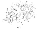
- FIG. 2 is a simplified view of one of the vessels 11A, 11B, in which only one of the sensor units 14 is illustrated, for clarity of understanding.
- the vessel 11 has a central body 12 with a longitudinal axis X (extending left to right as viewed in Figure 2 ).
- a sensor unit 14 is mounted in association with said body 12.
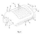
- the sensor unit 14 includes an arcuate array of ultrasonic sensors 16 for inspecting a pipe wall.
- the sensor unit 14 includes a skid 18 having an outer surface 20 intended to run adjacent or in contact with a pipe wall, in use.
- the outer surface 20 is arcuate in a circumferential direction with respect to the longitudinal axis X.
- the sensors 16 also define an arcuate inspection plane in a circumferential direction with respect to the longitudinal axis X.
- the inspection plane is arranged at a stand off from the outer surface of the skid 18 (e.g. radially inward of the outer surface 20), for protecting the sensors 16 against wear or other damage from contact with the pipe wall.
- the ultrasonic sensors 16 within the inspection array can be orientated normally to the pipe wall for wall thickness evaluation or at an angle to the pipe wall so as to induce shear waves and identify any cracks in the pipeline, for example.
- the apparatus 10 includes a spring-loaded mechanism 22 for permitting movement of the sensor unit 14 with respect to the longitudinal axis of the central body 12, e.g. in response to changes in bore diameter.
- the mechanism 22 is configured for biasing the sensor unit 14 in a generally radial direction, in order to bias the outer surface 20 of the skid 18 in the direction of a pipe wall. More particularly, the mechanism 22 is configured for moving the sensor unit 14 between a first radial position (e.g. a retracted position for use in a small diameter bore) and a second radial position (e.g. an extended position for use in a large diameter bore), in response to changes in pipe diameter.
- the mechanism 22 is configured to position the sensor unit 14 at an appropriate radial position (e.g. intermediate said first and second radial positions), depending on the size of the bore through which the apparatus 10 is passing.
- the apparatus 10 can be used for inspection of multi-diameter pipelines or across a range of pipelines having different diameters.
- the mechanism 22 includes first and second suspension members 24, 26 configured for biasing the sensor unit 14 in the direction of a pipe wall (e.g. in a radial or outward direction relative to the longitudinal axis X).
- the first and second suspension members 24, 26 are axially off set from one another, with respect to the longitudinal axis of the central body 12.
- the first and second suspension members 24, 26 are connected to body 12 by a spring-biased pivotal connection 25, so as to be configured to pivot relative to said longitudinal axis of the central body 12.
- the suspension members 24, 26 are biased towards said second radial position (i.e. an extended position relative to the body 12).
- the suspension members 24, 26 act as spring-biased struts or arms which are movable relative to the central body 12 of the vessel 11, for positioning the sensor unit 14 adjacent the pipe wall.
- a roller 27 is provided at the end of each suspension member 24, 26, for rolling contact with the internal surface of a pipe along which the apparatus is travelling, in use.
- the first and second suspension members 24, 26 form part of a linkage 28, which is configured for movement of the sensor unit 14 radially with respect to the longitudinal axis of the central body 12, e.g. between the first radial position and second radial position, in response to changes in bore diameter as the suspension rollers 27 react against the pipe wall.
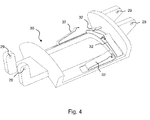
- the linkage 28 includes a carrier 30 arranged for movement with said first and second suspension members 24, 26.
- the sensor unit 14 is mounted on said carrier 30.
- the carrier 30 is mounted between the first and second suspension members 24, 26, and the carrier 30 is arranged to remain parallel with the longitudinal axis of the central body 12 during movement of the sensor unit 14.
- the carrier 30 includes pivot points 29 for connection to the first and second suspension members 24, 26.
- the carrier 30 biasing elements in the form of leaf springs 32, which are arranged beneath the sensor unit 14.
- the biasing elements provide local biasing of the sensor unit 14 relative to the longitudinal axis of the central body 12, e.g. in the direction of the pipe wall.
- the spring-loaded mechanism 22 ensures that the sensors 16 are deployed adjacent the pipe wall, even in bends (where conventional systems fail or are highly unreliable). Moreover, the localised biasing of the sensor unit 14 on the carrier 30 assists in providing correct orientation and clamping force of the skid 18 against the pipe wall.
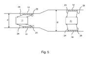
- the apparatus 10 is suited for use inspecting a pipeline having a first section with a first bore diameter and a second section with a second bore diameter (i.e. less than or greater than the first bore diameter).
- the apparatus 10 can be sent on a continuous run through said first and second sections of the pipeline.
- the mechanism 22 is used to bias the sensor unit 14 against an inner surface of the first section and to automatically bias the sensor unit 14 against an inner surface of the second section upon a change in bore diameter between said first and second sections of the pipeline.
- An example is shown in Figure 5 .
- the apparatus 10 permits accurate modelling of the biasing forces required to maintain the skid 18 in contact with the pipe wall, providing a significant improvement over conventional skid designs.
- the apparatus 10 is advantageous, at least insofar as it should reduce the time required to design a skid for a given diameter of pipe, by allowing the required forces to be calculated in an early stage in the design procedure, reducing or obviating the need for optimisation loops and other acts of trial and error.
- linkage 28 permits use of the apparatus across a range of pipeline diameters, including improved tracking of the pipe bore, especially in bends and through restrictive pipeline features such as tapers, valves, etc.
- the linkage 28 permits use of the apparatus across a range of pipeline diameters, including improved tracking of the pipe bore.
- Each linkage 28 can move independently with respect to the other linkages 28 on the vessels 11A,11B. This enables the apparatus to pass through and inspect tight bend diameters and difficult or restrictive pipeline features such as tapers, valves, etc. It is envisaged that exemplary embodiments will be cable of inspection through 1D bends and mitre bends.
- the linkage 28 takes the form of a 4-bar linkage, consisting of the body 12, suspension members 24, 26 and carrier 30.
- Other forms of collapsible linkage may be applicable, e.g. a 5-bar linkage including said suspension members 24, 26, configured to ensure that the sensor unit 14 tracks the pipe wall irrespective of the attitude of the internal pig body 12 within the pipeline.
- Figure 1 shows a twin vessel arrangement with two groups of circumferentially spaced sensor units, wherein the two groups of sensor units are axially offset and out of phase, in order to provide 360 degrees of inspection coverage.
- exemplary embodiments may incorporate three or more axially offset groups of circumferentially spaced sensor units on one, two or more vessels, for providing 360 degrees of inspection coverage.
- Figure 1 shows an embodiment in which there are four sensor units per group of sensor units, other embodiments may consist of three or more sensor units per group.
- the apparatus 10 is configured so that the combined inspection data from the sensors 16 from the groups of sensor units 14 provides 360 degrees of coverage (with respect to a longitudinal axis of the apparatus 10) irrespective of the position of relative position of the sensor units to one another, e.g. if one or more of the sensor units 14 are arranged at different radial positions. This enables the apparatus 10 to provide 360 degree inspection of the internal surface of a pipeline having multiple bore diameters, or across a range of different pipe diameters.
- Figures 1 and 2 are described with spring-loaded suspension members in the form of pivotable arms or struts, other types of suspension may be employed.
- Figures 2 to 4 are described with leaf springs for local biasing of the sensor unit on the carrier, other forms of resilient biasing element may be incorporated.
Landscapes
- Engineering & Computer Science (AREA)
- General Engineering & Computer Science (AREA)
- Chemical & Material Sciences (AREA)
- Health & Medical Sciences (AREA)
- Mechanical Engineering (AREA)
- Physics & Mathematics (AREA)
- Combustion & Propulsion (AREA)
- Life Sciences & Earth Sciences (AREA)
- Analytical Chemistry (AREA)
- Biochemistry (AREA)
- General Health & Medical Sciences (AREA)
- General Physics & Mathematics (AREA)
- Immunology (AREA)
- Pathology (AREA)
- Investigating Or Analyzing Materials By The Use Of Ultrasonic Waves (AREA)
Priority Applications (5)
| Application Number | Priority Date | Filing Date | Title |
|---|---|---|---|
| EP11167721A EP2527708A1 (de) | 2011-05-26 | 2011-05-26 | Vorrichtung zur Inspektion von Pipelines und Pipeline-Inspektionsverfahren |
| US13/481,234 US20130025370A1 (en) | 2011-05-26 | 2012-05-25 | Apparatus for pipeline inspection and method of pipeline inspection |
| CA2777865A CA2777865A1 (en) | 2011-05-26 | 2012-05-25 | Apparatus for pipeline inspection and method of pipeline inspection |
| AU2012203074A AU2012203074A1 (en) | 2011-05-26 | 2012-05-25 | Apparatus for pipeline inspection and method of pipeline inspection |
| CN2012101682009A CN102798665A (zh) | 2011-05-26 | 2012-05-28 | 用于管路检查的设备和管路检查的方法 |
Applications Claiming Priority (1)
| Application Number | Priority Date | Filing Date | Title |
|---|---|---|---|
| EP11167721A EP2527708A1 (de) | 2011-05-26 | 2011-05-26 | Vorrichtung zur Inspektion von Pipelines und Pipeline-Inspektionsverfahren |
Publications (1)
| Publication Number | Publication Date |
|---|---|
| EP2527708A1 true EP2527708A1 (de) | 2012-11-28 |
Family
ID=44117975
Family Applications (1)
| Application Number | Title | Priority Date | Filing Date |
|---|---|---|---|
| EP11167721A Withdrawn EP2527708A1 (de) | 2011-05-26 | 2011-05-26 | Vorrichtung zur Inspektion von Pipelines und Pipeline-Inspektionsverfahren |
Country Status (5)
| Country | Link |
|---|---|
| US (1) | US20130025370A1 (de) |
| EP (1) | EP2527708A1 (de) |
| CN (1) | CN102798665A (de) |
| AU (1) | AU2012203074A1 (de) |
| CA (1) | CA2777865A1 (de) |
Cited By (2)
| Publication number | Priority date | Publication date | Assignee | Title |
|---|---|---|---|---|
| CN105806955A (zh) * | 2014-12-30 | 2016-07-27 | 中核武汉核电运行技术股份有限公司 | 一种小径管内壁检查超声探头夹持结构 |
| EP4602398A4 (de) * | 2022-10-12 | 2026-01-28 | Ontario Power Generation Inc | Ultraschallvorrichtungen und verfahren zur kraftstoffkanalinspektion |
Families Citing this family (16)
| Publication number | Priority date | Publication date | Assignee | Title |
|---|---|---|---|---|
| EP2527707A1 (de) * | 2011-05-26 | 2012-11-28 | Pii Limited | Vorrichtung zur Leitungsprüfung |
| US20140352438A1 (en) * | 2013-05-28 | 2014-12-04 | General Electric Company | Device for ultrasonic inspection |
| US10036680B2 (en) | 2015-03-19 | 2018-07-31 | General Electric Company | Pipeline sensor carrier |
| US10605776B2 (en) | 2016-06-13 | 2020-03-31 | General Electric Company | Power systems and methods for a pipeline inspection apparatus |
| US20180231507A1 (en) * | 2017-02-15 | 2018-08-16 | Microline Technology Corporation | Method and apparatus for metamaterial enhanced chaotic cavity transducer |
| CN107740907B (zh) * | 2017-11-15 | 2023-07-25 | 珠海深圳清华大学研究院创新中心 | 一种管道机器人检测装置及管道故障检测方法 |
| US10545121B2 (en) * | 2018-05-23 | 2020-01-28 | Pii Pipetronix Gmbh | Pipeline inspection systems and methods |
| CN109342550A (zh) * | 2018-09-17 | 2019-02-15 | 西华大学 | 小直径管道漏磁检测装置 |
| CN109541015B (zh) * | 2018-11-01 | 2022-08-19 | 中国海洋石油集团有限公司 | 隔水管边管内检测器 |
| CN111207268B (zh) * | 2020-02-03 | 2022-08-30 | 成都普崔克机电有限公司 | 一种管道检测装置 |
| CN115956201A (zh) * | 2020-06-02 | 2023-04-11 | 蓬勃科技有限公司 | 用于检测管道的管壁状况的装置 |
| EP4271988A1 (de) * | 2020-12-29 | 2023-11-08 | SABIC Global Technologies B.V. | Rohrinspektionsvorrichtungen und -systeme sowie verfahren zur verwendung davon |
| US12313595B2 (en) * | 2021-12-15 | 2025-05-27 | Pure Technologies U.S. Inc. | Apparatus, systems and methods for pipeline condition assessment |
| CN114738600B (zh) * | 2022-03-15 | 2023-11-03 | 香港理工大学深圳研究院 | 一种模块化的管道缺陷检测软体机器人 |
| CN116296900B (zh) * | 2023-05-25 | 2023-07-25 | 四川职业技术学院 | 一种测量河底输气管道剪切应力变化的控制系统及方法 |
| CN119178078B (zh) * | 2024-10-16 | 2026-04-17 | 中国长江电力股份有限公司 | 一种大变径比多关节主被动驱动管路机器人 |
Citations (5)
| Publication number | Priority date | Publication date | Assignee | Title |
|---|---|---|---|---|
| US6196075B1 (en) * | 1997-10-22 | 2001-03-06 | Pipetronix Gmbh | Device for inspection of pipes |
| US20030183022A1 (en) * | 2002-03-28 | 2003-10-02 | Sapelnikov Uriy A. | Sensors carrier for in-tube inspection scraper |
| US20050126316A1 (en) * | 2002-03-12 | 2005-06-16 | Thomas Richter | Segment of a sensor-supporting element for a scraper-type device |
| GB2424255A (en) * | 2005-03-17 | 2006-09-20 | Pii Ltd | A sensor system for an in-line inspection tool |
| US20090101337A1 (en) * | 2007-10-18 | 2009-04-23 | Neidhardt Deitmar J | Method and apparatus for detecting defects in oilfield tubulars |
Family Cites Families (5)
| Publication number | Priority date | Publication date | Assignee | Title |
|---|---|---|---|---|
| DE10262232B4 (de) * | 2002-01-22 | 2008-07-03 | Pii Pipetronix Gmbh | Verfahren und Vorrichtung zum Untersuchen von Rohrleitungen |
| JP4232623B2 (ja) * | 2003-12-19 | 2009-03-04 | Jfeエンジニアリング株式会社 | 管内検査台車および管内検査装置 |
| CN2758766Y (zh) * | 2004-09-24 | 2006-02-15 | 中国石化集团胜利石油管理局钻井工艺研究院 | 一种管道检测装置使用的平行四边形变径机构 |
| GB0816804D0 (en) * | 2008-09-13 | 2008-10-22 | Offshore Marine Technology Ltd | Inspection device |
| KR101103805B1 (ko) * | 2009-08-06 | 2012-01-06 | 한전케이피에스 주식회사 | 착탈가능한 탐촉자를 구비한 검사장치 |
-
2011
- 2011-05-26 EP EP11167721A patent/EP2527708A1/de not_active Withdrawn
-
2012
- 2012-05-25 US US13/481,234 patent/US20130025370A1/en not_active Abandoned
- 2012-05-25 AU AU2012203074A patent/AU2012203074A1/en not_active Abandoned
- 2012-05-25 CA CA2777865A patent/CA2777865A1/en not_active Abandoned
- 2012-05-28 CN CN2012101682009A patent/CN102798665A/zh active Pending
Patent Citations (5)
| Publication number | Priority date | Publication date | Assignee | Title |
|---|---|---|---|---|
| US6196075B1 (en) * | 1997-10-22 | 2001-03-06 | Pipetronix Gmbh | Device for inspection of pipes |
| US20050126316A1 (en) * | 2002-03-12 | 2005-06-16 | Thomas Richter | Segment of a sensor-supporting element for a scraper-type device |
| US20030183022A1 (en) * | 2002-03-28 | 2003-10-02 | Sapelnikov Uriy A. | Sensors carrier for in-tube inspection scraper |
| GB2424255A (en) * | 2005-03-17 | 2006-09-20 | Pii Ltd | A sensor system for an in-line inspection tool |
| US20090101337A1 (en) * | 2007-10-18 | 2009-04-23 | Neidhardt Deitmar J | Method and apparatus for detecting defects in oilfield tubulars |
Cited By (3)
| Publication number | Priority date | Publication date | Assignee | Title |
|---|---|---|---|---|
| CN105806955A (zh) * | 2014-12-30 | 2016-07-27 | 中核武汉核电运行技术股份有限公司 | 一种小径管内壁检查超声探头夹持结构 |
| CN105806955B (zh) * | 2014-12-30 | 2018-09-28 | 中核武汉核电运行技术股份有限公司 | 一种小径管内壁检查超声探头夹持结构 |
| EP4602398A4 (de) * | 2022-10-12 | 2026-01-28 | Ontario Power Generation Inc | Ultraschallvorrichtungen und verfahren zur kraftstoffkanalinspektion |
Also Published As
| Publication number | Publication date |
|---|---|
| US20130025370A1 (en) | 2013-01-31 |
| AU2012203074A1 (en) | 2012-12-13 |
| CN102798665A (zh) | 2012-11-28 |
| CA2777865A1 (en) | 2012-11-26 |
Similar Documents
| Publication | Publication Date | Title |
|---|---|---|
| US20130025370A1 (en) | Apparatus for pipeline inspection and method of pipeline inspection | |
| US20120297882A1 (en) | Apparatus for pipeline inspection | |
| EP3572781B1 (de) | Systeme und verfahren zur pipeline-inspektion | |
| US20130133429A1 (en) | Apparatus for pipeline inspection | |
| US20120325004A1 (en) | Apparatus for pipeline inspection and method of pipeline inspection | |
| US7798023B1 (en) | Linkage assembly for in-line inspection tool | |
| US4105972A (en) | Pipeline inspection vehicle for detecting defects in pipeline walls | |
| US10705051B2 (en) | Magnetizers for pigging tools | |
| KR102153521B1 (ko) | 실링 성능을 향상시킨 배관 검사 장치 | |
| US7154264B2 (en) | System and method using a collapsable coil for inspection of pipelines having internal restrictions | |
| US8373411B2 (en) | Sensor system for an in-line inspection tool | |
| NO172956B (no) | Anordning for maaling og skadefri materialproevning paa utlagte roerledninger | |
| CN111043445A (zh) | 管道内检测车 | |
| US8291780B2 (en) | Sensor finger module for a pipeline inspection tool | |
| CA2841596C (en) | Method and sensor mount for measuring seam peaking in pipes by means of ultrasonic inspection | |
| EP0254144A2 (de) | Messgerät zur Feststellung von Unrundheiten an verlegten Rohrleitungen | |
| US7021156B2 (en) | Measurement device for determining the straightness of shafts or shaft tunnels | |
| CA3005840A1 (en) | Pipeline inspection systems and methods | |
| CA2992363C (en) | Magnetizer for pigging tools | |
| US11579118B2 (en) | Single point contact triaxial sensor head for an inline inspection tool | |
| CN121296829A (zh) | 一种水利工程用管道质量检测装置 | |
| RU90209U1 (ru) | Автономный магнитный дефектоскоп контроля трубопроводов | |
| JPH09506703A (ja) | コンジット内を通して機器を搬送する装置およびその使用法 | |
| MXPA98004654A (en) | Screener to determine the position of tuber |
Legal Events
| Date | Code | Title | Description |
|---|---|---|---|
| PUAI | Public reference made under article 153(3) epc to a published international application that has entered the european phase |
Free format text: ORIGINAL CODE: 0009012 |
|
| AK | Designated contracting states |
Kind code of ref document: A1 Designated state(s): AL AT BE BG CH CY CZ DE DK EE ES FI FR GB GR HR HU IE IS IT LI LT LU LV MC MK MT NL NO PL PT RO RS SE SI SK SM TR |
|
| AX | Request for extension of the european patent |
Extension state: BA ME |
|
| STAA | Information on the status of an ep patent application or granted ep patent |
Free format text: STATUS: THE APPLICATION IS DEEMED TO BE WITHDRAWN |
|
| 18D | Application deemed to be withdrawn |
Effective date: 20130529 |