EP2527721A2 - Luminaire - Google Patents
Luminaire Download PDFInfo
- Publication number
- EP2527721A2 EP2527721A2 EP12159345A EP12159345A EP2527721A2 EP 2527721 A2 EP2527721 A2 EP 2527721A2 EP 12159345 A EP12159345 A EP 12159345A EP 12159345 A EP12159345 A EP 12159345A EP 2527721 A2 EP2527721 A2 EP 2527721A2
- Authority
- EP
- European Patent Office
- Prior art keywords
- light
- outer case
- luminaire
- inner case
- opening
- Prior art date
- Legal status (The legal status is an assumption and is not a legal conclusion. Google has not performed a legal analysis and makes no representation as to the accuracy of the status listed.)
- Withdrawn
Links
Images







Classifications
-
- F—MECHANICAL ENGINEERING; LIGHTING; HEATING; WEAPONS; BLASTING
- F21—LIGHTING
- F21V—FUNCTIONAL FEATURES OR DETAILS OF LIGHTING DEVICES OR SYSTEMS THEREOF; STRUCTURAL COMBINATIONS OF LIGHTING DEVICES WITH OTHER ARTICLES, NOT OTHERWISE PROVIDED FOR
- F21V15/00—Protecting lighting devices from damage
- F21V15/01—Housings, e.g. material or assembling of housing parts
- F21V15/015—Devices for covering joints between adjacent lighting devices; End coverings
-
- F—MECHANICAL ENGINEERING; LIGHTING; HEATING; WEAPONS; BLASTING
- F21—LIGHTING
- F21S—NON-PORTABLE LIGHTING DEVICES; SYSTEMS THEREOF; VEHICLE LIGHTING DEVICES SPECIALLY ADAPTED FOR VEHICLE EXTERIORS
- F21S4/00—Lighting devices or systems using a string or strip of light sources
-
- F—MECHANICAL ENGINEERING; LIGHTING; HEATING; WEAPONS; BLASTING
- F21—LIGHTING
- F21Y—INDEXING SCHEME ASSOCIATED WITH SUBCLASSES F21K, F21L, F21S and F21V, RELATING TO THE FORM OR THE KIND OF THE LIGHT SOURCES OR OF THE COLOUR OF THE LIGHT EMITTED
- F21Y2115/00—Light-generating elements of semiconductor light sources
- F21Y2115/10—Light-emitting diodes [LED]
Definitions
- Embodiments described herein relate generally to a luminaire including a light-emitting element such as an LED (light-emitting diode) as a light source.
- a light-emitting element such as an LED (light-emitting diode) as a light source.
- a luminaire including a semiconductor light-emitting element such as an LED as a light source is being spread.
- the luminaire of this type is assembled by, for example, mounting plural light-emitting elements on a substrate side by side, thermally sticking and fixing the substrate to an appliance main body made of metal, and attaching a case surrounding the substrate to the appliance main body.
- An opening for extracting lights emitted from the plural light-emitting elements is provided in the case.
- a light distribution member for improving the appearance of the light is attached to the opening.
- a luminaire in general, according to one embodiment, includes an insulative inner case having housed therein a substrate mounted with a light-emitting element and an outer case made of metal having the inner case housed therein.
- the inner case includes a first opening for allowing light emitted from the light-emitting element to pass.
- the outer case includes an insertion opening for inserting the inner case and a second opening overlapping the first opening.
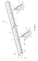
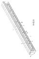
- a luminaire 100 according to an embodiment is explained below with reference to FIGS. 1 to 7 .
- the same components are denoted by the same reference numerals and signs and redundant explanation of the components is omitted.
- the luminaire 100 is mainly used outdoors.
- the luminaire 100 is used for irradiating light on and lighting up an outer wall of a building in order to reproduce a beautiful night scene.
- a luminaire shown in FIG. 1 has a structure in which two luminaires 100 are coupled in a longitudinal direction.
- the luminaire 100 includes an attachment member F fixed to a structure such as a building.
- the attachment member F includes a pedestal p and an arm a.
- the pedestal p is fixed to the structure.
- the luminaire 100 is attached to a distal end side of the arm a.
- the arm a can pivot with one end side set as a fulcrum.
- a direction of light irradiated from the luminaire 100 can be changed as appropriate by adjusting a pivoting angle of the arm a.
- the light irradiated from the luminaire 100 is directed upward in the figure.
- the attachment member F is not limited to the configuration explained above and only has to be an attachment member that can support the luminaire 100 attached thereto.
- One luminaire 100 may be set or plural luminaires 100 may be coupled and set.
- the number of luminaires 100 only has to be selected as appropriate according to an object on which light is irradiated.
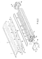
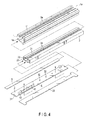
- the luminaire 100 includes an outer case 1, an inner case 2 housed and arranged on the inside of the outer case 1, a light source section 3 arranged on the inside of the inner case 2, a power supply circuit 4, an optical component 5 and a first cover 6 disposed on a front surface side of the light source section 3 (a light irradiating direction side), and a second cover 7 disposed on the front surface side of the first cover 6.
- the front surface side indicates a side on which the light of the light source section 3 is extracted. In FIG. 1 , the front surface side is an upper side in FIG. 1 .
- the outer case 1 is molded in a cylindrical shape by extrusion molding of an aluminum material having high thermal conductivity. More specifically, the outer case 1 has a laterally long shape extending in a substantially horizontal direction. A space for housing the inner case 2 explained later is provided on the inside of the outer case 1.
- the outer case 1 is opened at both ends in a longitudinal direction thereof.
- An opening 11 (a second opening) (see FIG. 2 ) having a rectangular shape along the longitudinal direction is formed on the front surface side thereof.
- the opening 11 functions as an irradiation opening for irradiating the light of the light source section 3.
- two openings at both the ends in the longitudinal direction of the outer case 1 are connected at both ends in the longitudinal direction of the opening 11 provided on the front surface side.
- the two openings at both the ends in the longitudinal direction of the outer case 1 function as insertion openings 1a for inserting the inner case 2.
- the outer case 1 is desirably molded by the extrusion molding. However, this is not a limitation. A method of molding the outer case 1 is not specifically limited and may be any method.
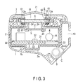
- Supporting sections 12 for supporting the first cover 6 are formed at both edges along the longitudinal direction of the opening 11 of the outer case 1 (see FIG. 3 ).
- the supporting sections 12 include groove-shaped sections 12a extending in the longitudinal direction. In other words, the groove-shaped sections 12a are respectively linearly provided along both the edges of the opening 11.
- an attachment supporting section 13 for connecting the attachment member F is provided on an outer surface of the outer case 1.
- the attachment supporting section 13 is provided over substantially the entire length of the outer case 1.
- the cross section of the attachment supporting section 13 has a C shape.
- An attachment rail (not shown) is inserted into the attachment supporting section 13 and fixed to the attachment member F by bolts.
- the outer case 1 is attached to the attachment member F and supported. If the two luminaires 100 are coupled, the attachment supporting section 13 receives a coupling member 80 explained later (see FIG. 11 ).
- a pair of end plate members 14 that respectively close the two openings at the both ends in the longitudinal direction of the outer case 1 are attached to the openings.
- the end plate members 14 have a shape substantially the same as the openings (see FIG. 2 ) of the outer case 1.
- the end plate member 14 on the left side in FIG. 2 is representatively shown.
- the end plate members 14 include groove-shaped sections 14a at edges on the front surface side.
- the groove-shaped sections 14a have a continuous shape bent in a substantially U shape.
- end plate members 14 include attachment supporting sections 14b having a C shape in cross section to be continuous to the attachment supporting section 13 of the outer case 1.
- the end plate members 14 are screwed and attached to the openings at both the ends in the longitudinal direction of the outer case 1 via not-shown seal members.
- seal-member disposing section 8 connected in an annular shape is formed around the opening 11 of the outer case 1.
- the seal-member disposing section 8 is a groove in which the groove-shaped sections 12a formed at the edges of the opening 11 of the outer case 1 and the groove-shaped sections 14a formed at the edges on the front surface side of the two end plate members 14 are connected in an annular shape.
- a ring-shaped seal member 62 is attached to the inside of the seal-member disposing section 8.
- the length of the seal member 62 is substantially equal to the length of the seal-member disposing section 8.
- the seal member 62 is attached over the edges of the opening 11 of the outer case 1 and the edges of the end plate members 14. In other words, the seal member 62 is attached across joining sections of the outer case 1 and the end plate members 14.
- an O ring circular in cross section formed of an elastic member such as synthetic rubber is used as the seal member 62.
- a space S for inserting a relatively thick cable C therethrough is provided besides the space for storing the inner case 2.
- the cable C is connected to a substrate 31 of the light source section 3 and functions as a power supply line for supplying power to plural light-emitting elements 32 mounted on the substrate 31.
- the space S is formed between an outer surface of the inner case 2 and an inner surface of the outer case 1. Therefore, the cable C can be wired on the outside of the inner case 2.
- the inner case 2 is a resin case having an insulation property. Like the outer case 1, the inner case 2 is molded in a cylindrical shape by extrusion molding. Both ends in the longitudinal direction of the inner case 2 are opened. A slit-shaped irradiation opening 21 (a first opening) extending along the longitudinal direction is formed on the front surface side of the inner case 2. The inner case 2 is inserted from one of the openings (the insertion openings 1a) at both the ends of the outer case 1 and arranged in the space on the inside of the outer case 1. At this point, the inner case 2 is attached in a posture in which the irradiation opening 21 overlaps the opening 11 of the outer case 1.
- a rail 2a functioning as a guide in inserting the inner case 2 via the insertion openings 1a at both the ends in the longitudinal direction of the outer case 1 is protrudingly provided on the outer surface of the inner case 2.
- the rail 2a is provided over the entire length of the inner case 2.
- the rail 2a is integrally formed by subjecting a part of the inner case 2 to shape processing.
- a step 1b for guiding the rail 2a of the inner case 2 is provided on the inner surface of the outer case 1.
- the step 1b is integrally formed by subjecting a part of the outer case 1 to shape processing and provided over the entire length of the outer case 1.
- the step 1b is provided on the inner surface of the outer case 1 and the rail 2a is provided on the outer surface of the inner case 2. Consequently, it is possible to simplify work for attaching the inner case 2 to the outer case 1 and simplify assembly work for the luminaire 100.
- the light source section 3 and the optical component 5 are attached to the inside of the inner case 2.
- Two holding grooves 22 for holding the light source section 3 are formed on a wall on the inner side of the inner case 2 to extend in the longitudinal direction.
- Holding grooves 23 for holding the optical component 5 are formed at both edges along the longitudinal direction of the irradiation opening 21 to extend in the longitudinal direction.
- Two light blocking louvers 24 (light-distribution control sections) standing toward the front surface side are integrally formed at the edges of the irradiation opening 21.
- the light blocking louvers 24 extend straight in the longitudinal direction of the inner case 2.
- the light blocking louvers 24 play a function of blocking the light emitted from the light source section 3 and controlling to distribute the light.
- the light source section 3 includes the substrate 31 and the plural light-emitting elements 32 mounted on the substrate 31.
- the light source section 3 is attached to a substrate attachment plate 33 having insulation properties.
- the substrate attachment plate 33 is held by the holding grooves 22 of the inner case 2. Consequently, the light source section 3 is housed and arranged in the inner case 2.
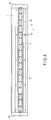
- the substrate 31 is formed in a substantially rectangular shape. As shown in FIGS. 6 and 7 , the plural light-emitting elements 32 are mounted linearly side by side with a predetermined space apart from one another along the longitudinal direction of the substrate 31. A distance between the light-emitting elements 32 adjacent to each other is substantially fixed. In this embodiment, the distance is about 50 mm.
- the substrate 31 is formed of a flat plate of glass epoxy resin (FR-4), which is an insulating material. On a surface side of the substrate 31, a wiring pattern formed of a copper foil is formed. A white resist layer is formed on the surface side of the substrate 31.
- FR-4 glass epoxy resin
- a glass composite substrate (CEM-3), a ceramics material, or the like can be applied.
- the substrate 31 is made of metal, a base substrate of metal in which an insulating layer is superimposed over the entire surface of a base plate having high thermal conductivity and excellent in thermal radiation properties such as aluminum can be applied.
- Each of the light-emitting elements 32 is, for example, a light-emitting diode (LED) and is an LED package of a surface mounting type.
- the light-emitting element 32 schematically includes an LED chip disposed in a main body formed of ceramics or synthetic resin and translucent resin for mold such as epoxy resin or silicone resin for sealing the LED chip.
- the LED chip is, for example, an LED chip that emits blue light.
- a phosphor is mixed in the translucent resin.
- An yellow phosphor that emits yellowish light, which is in a complementary relation with blue light, is used as the phosphor to enable the light-emitting element 32 to emit white light.
- a bare chip of the LED may be directly mounted on the substrate 31 or an LED of a bullet type may be mounted.
- a mounting system or method is not specifically limited.
- the power supply circuit 4 is provided on the substrate 31 of the light source section 3. Specifically, circuit components 41 such as a rectifier, a capacitor, and a resistance element included in the power supply circuit 4 are mounted on the substrate 31 of the light source section 3. Therefore, the light-emitting elements 32 and the circuit components 41 are mounted on the same substrate 31.
- the circuit components 41 are desirably mounted along a row of the linearly arranged light-emitting elements 32 and on both sides or one side of the row. Consequently, it is possible to effectively use a mounting area of the substrate 31.
- the power supply circuit 4 is connected to a not-shown commercial alternating-current power supply via the cable C (see FIG. 3 ) connected to a power supply terminal 42.
- the power supply circuit 4 functions to receive power supply from the commercial alternating-current power supply and generate a direct-current output.
- the power supply circuit 4 is configured by, for example, connecting a smoothing capacitor between output terminals of a full-wave rectifier circuit and connecting a direct-current voltage converting circuit and current detecting means to the smoothing capacitor.
- the power supply circuit 4 is connected to the light-emitting elements 32 via the wiring pattern.
- the power supply circuit 4 supplies the direct-current output to the light-emitting elements 32 and controls to light the light-emitting elements 32.
- the optical component 5 is, for example, a prism sheet.
- the prism sheet 5 has translucency and is formed in an elongated rectangular shape. Both ends along the longitudinal direction of the prism sheet 5 are held in the holding grooves 23 of the inner case 2.
- the prism sheet 5 closes the irradiation opening 21 of the inner case 2 and is arranged on the front surface side of the row of the light-emitting elements 32.
- the prism sheet 5 has fine grooves formed on a surface and has a function of refracting and diffusing lights emitted from the light-emitting elements 32 in the longitudinal direction (a first direction).
- the two light blocking louvers 24 control to distribute the lights in a direction (a second direction) orthogonal to a diffusing direction of the lights by the prism sheet 5 to block the lights transmitted through the optical component 5 not to spread in a latitudinal direction of the irradiation opening 21.
- the lights emitted from the plural light-emitting elements 32 are diffused in the longitudinal direction by the optical component 5 in this way, the lights are controlled to be distributed in the latitudinal direction by the light blocking louvers 24. Consequently, it is possible to prevent occurrence of glare and obtain satisfactory illumination light.
- the first cover 6 has a rectangular tabular shape and is, for example, a transparent glass plate. Both end edges along the longitudinal direction of the glass plate 6 are placed at front ends of the light blocking louvers 24 formed in the inner case 2 and placed on the supporting sections 12 of the outer case 1. The front surface side of both the end edges of the glass plate 6 along the longitudinal direction is pressed from the front surface side by two pressing plates 61 and fastened and fixed to the outer case 1. The height of the light blocking louvers 24 is designed to height flush with the supporting sections 12 of the outer case 1 in a state in which the inner case 2 is housed and arranged in the outer case 1.
- Each of the pressing plates 61 has plural (in this embodiment, seven) screw holes spaced apart in the longitudinal direction.
- the pressing plates 61 are screwed and fixed to the front surface side of the outer case 1 and the two end plate members 14.
- the seal member 62 housed and arranged in the annular seal-member disposing section 8 formed by the groove-shaped sections 12a of the outer case 1 and the groove-shaped sections 14a of the end plate members 14 is pressed by the glass plate 6 toward the supporting sections 12 and elastically deformed. Therefore, the opening 11 of the outer case 1 is sealed by the glass plate 6 and the seal member 62 to prevent moisture and dust from intruding into the inside of the outer case 1. As a result, waterproof performance can be secured.
- the second cover 7 is disposed to be spaced apart on the front surface side of the first cover 6 and functions to cover the front surface side of the outer case 1.
- a center 71 of the second cover 7 is bent to be slightly convex to the front surface side. At least the center 71 has translucency.
- the second cover 7 configured in this way has a function of further improving the waterproof performance and protecting the first cover 6.
- the second cover 7 is not provided, it is likely that water accumulates in the concave section and deterioration in the waterproof performance and deterioration in transmissivity of light due to adhesion of soil to a surface of the first cover 6 occur.
- the second cover 7 is provided as in this embodiment, for example, water dropping and adhering to a surface of the second cover 7 flows down according to the convex shape of the center 71. Therefore, it is possible to secure the waterproof performance for a long period. Further, it is possible to suppress the adhesion of soil to the first cover 6 and suppress the deterioration in the transmissivity of light.
- the light source section 3 (including the power supply circuit 4) attached to the substrate attachment plate 33 and the prism sheet functioning as the optical component 5 are incorporated into the inner case 2.
- the substrate attachment plate 33 is inserted through from one side of the openings at both the ends of the inner case 2 and slid to the holding grooves 22 of the inner case 2 to be mounted.
- the prism sheet 5 is slid to the holding grooves 23 of the inner case 2 to be mounted. Consequently, the light source section 3 and the optical component 5 are held by the insulative inner case 2.
- the inner case 2 is attached to the outer case 1. Specifically, the inner case 2 inserted from one side (the insertion opening 1a) of the openings at the both ends of the outer case 1 and is slid to the space on the inner side of the outer case 1.
- the end plate members 14 are screwed and attached to the openings at both the ends of the outer case 1 via the seal members (not shown).
- the ring-shaped seal member 62 is disposed in the seal-member disposing section 8 formed by the groove-shaped sections 12a of the outer case 1 and the groove-shaped sections 14a of the end plate members 14.
- the first cover 6 is arranged in a place for closing the opening 11 of the outer case 1 to cover the seal member 62.
- the two pressing plates 61 are arranged to be partially placed on both the edges of the first cover 6.
- the two pressing plates 61 are screwed and fixed to the outer case 1.
- the first cover 6 has a size for covering the entire seal member 62. Therefore, by fastening and fixing the first cover 6 using the two pressing plates 61, the seal member 62 arranged around the opening 11 is uniformly pressed over the entire length of the seal member 62 and air tightness is improved.
- the second cover 7 is slid to the front surface side of the outer case 1 and arranged from one side at both the ends of the outer case 1. Thereafter, two attachment screws S ( FIG. 2 ) are screwed into screw holes 14e provided on sidewalls of the end plate members 14 from a side to fix the second cover 7.
- the seal member 62 is arranged in the seal-member disposing section 8 formed by connecting the groove-shaped sections 14a on the front surface side of the end plate members 14, which closes the openings at both the ends in the longitudinal direction of the outer case 1, and the groove-shaped sections 12a on the front surface side of the outer case 1. Consequently, it is possible to improve the air tightness of the opening 11 of the outer case 1 and secure the sufficient waterproof performance.
- the light source section 3 and the optical component 5 can be inserted and incorporated from the opening of the inner case 2.
- the inner case 2 in which the light source section 3 and the optical component 5 are disposed can be inserted and incorporated from the insertion opening 1a of the outer case 1. Therefore, according to this embodiment, it is possible to simplify the process for assembling the luminaire 100.
- the light source section 3 is incorporated in the resin case having insulating properties, which is the inner case 2, it is possible to secure the insulating properties with a compact form. Since an additional component for insulation is unnecessary and the inner case 2 itself plays an insulating function, it is possible to surely and easily insulate the substrate 31.
- the opening 11 of the outer case 1 is sealed over the groove-shaped sections 12a of the outer case 1 and the groove-shaped sections 14a of the end plate members 14 and using the ring-shaped seal member 62. Therefore, it is possible to improve the waterproof performance and realize an effect that work for attaching the seal member 62 is simplified.
- the luminaire 100 having the structure explained above emits illumination light as explained below.
- the light-emitting elements 32 When electric power is supplied to the power supply circuit 4 via the substrate 31, the light-emitting elements 32 are energized and lit. Lights emitted from the light-emitting elements 32 are transmitted through the prism sheet functioning as the optical component 5 and the first and second covers 6 and 7 and irradiated in a target direction.
- the lights emitted from the light-emitting elements 32 to travel straight mainly in the front surface side direction are made incident on the optical component 5, as indicated by arrows in FIG. 8 , the lights travel to be refracted and diffused in the longitudinal direction.
- the lights emitted from the light-emitting elements 32 are diffused to spread in the longitudinal direction. Therefore, even if the light-emitting elements 32 are spaced apart as in this embodiment (a spaced distance L), continuity of the lights in the longitudinal direction is suppressed from being interrupted. Therefore, it is possible to secure the continuity of the lights.
- the light blocking louvers 24 are provided at the edges of the irradiation opening 21, it is difficult to visually recognize the lights directly emitted from the light-emitting elements 32. Therefore, it is possible to show an irradiated surface as if the irradiated surface is uniformly shining and further secure the continuity of the lights.
- plural luminaires 100 are coupled in the longitudinal direction
- plural substrates 31 are arranged in the longitudinal direction.
- the spaced distance L1 is set to about 50 mm and is equal to the spaced distance L.
- a coupling section of the luminaires 100 i.e., a boundary of the adjacent substrates 31, it is possible to secure the continuity of the lights in the same manner as the continuity of the lights in the longitudinal direction in the one substrate 31.
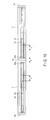
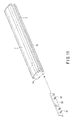
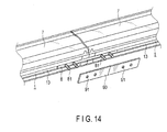
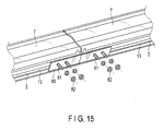
- a coupling structure in coupling the plural luminaires 100 in the longitudinal direction is explained with reference to FIGS. 11 to 16 .
- the coupling member 80 shown in FIG. 11 has a substantially C shape as a side shape and is formed in a laterally long rectangular shape.
- Plural bolt members 81 vertically provided in a direction orthogonal to the longitudinal direction are provided on the near side in the figure of the coupling member 80.
- the plural bolt members 81 are fixed to the coupling member 80, for example, by welding.
- four bolt members 81 are provided with a predetermined space apart from one another.
- An external form of the side shape in the coupling member 80 is a form substantially equivalent to an inner shape of the C-shaped attachment supporting section 13 formed in the outer case 1. Therefore, as shown in FIG. 12 , the coupling member 80 can be slid and inserted into the inner side of the attachment supporting section 13. In this case, the bolt members 81 are located to project to the outer side from an opened section of the C-shaped attachment supporting section 13.
- the coupling member 80 is disposed across a boundary portion where the two luminaires 100 are coupled. In other words, the coupling member 80 is inserted and disposed across the attachment supporting sections 13 of the luminaires adjacent to each other.
- a fixing plate 90 is attached to the coupling member 80 from the outer side.
- the fixing plate 90 is a rectangular plate material. Through-holes 91 are formed to correspond to disposed positions of the bolt members 81.
- Such a fixing plate 90 is attached to the attachment supporting sections 13 from the outer side such that the bolt members 81 are inserted through the through-holes 91.
- the coupling member 80 may be used as the attachment rail as well. Consequently, it is possible to realize common use of components and reduce the number of components.
- the plural luminaires 100 are coupled in the longitudinal direction.
- the plural substrates 31 are disposed side by side in the longitudinal direction in one luminaire, it is also possible to secure the continuity of the lights in the longitudinal direction by setting a spaced distance between the light-emitting elements 32a adjacent to each other in the substrates 31 adjacent to each other to be equal to a spaced distance between the light-emitting elements 32 adjacent to each other in the one substrate 31.
- the light-emitting elements 32 are mounted with the predetermined spaced distance L apart from one another in the longitudinal direction of the substrate 31 and the number of the light-emitting elements 32 is reduced, it is possible to secure the continuity of the lights in the longitudinal direction. This is economically advantageous and makes it possible to provide a luminaire that can secure the continuity of the lights in the longitudinal direction.
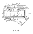
- FIGS. 17 to 19 A second embodiment is explained with reference to FIGS. 17 to 19 .
- Components same as or equivalent to the components in the first embodiment are denoted by the same reference numerals and signs and redundant explanation of the components is omitted.
- light blocking louvers 34 functioning as light-distribution control sections are disposed on the substrate 31.
- the light blocking louvers 34 are made of synthetic resin and formed as tabular strips having a square shape.
- Elastically deformable engaging sections 34a are integrally formed on lower end sides of the light blocking louvers 34.
- slits 31a are formed along the longitudinal direction on both sides of the light-emitting elements 32 in the substrate 31. Therefore, the engaging sections 34a of the light blocking louvers 34 are elastically deformed and press-fit in and attached to the slits 31a.
- the light blocking louvers 34 are disposed to be vertically provided on both the sides of the light-emitting elements 32 along the latitudinal direction of the substrate 31.
- the lights emitted from the light-emitting elements 32 are controlled to be distributed by the light blocking louvers 34, the lights are transmitted through the optical component 5. Therefore, compared with direct irradiation of the lights from the light-emitting elements 32 on the optical component 5, it is possible to show an irradiated surface as if the irradiated surface is uniformly shining and further secure the continuity of the lights. Since the light blocking louvers 34 are disposed in the substrate 31, the light blocking louvers 34 are located in positions close to the light-emitting elements 32. As a result, it is easy to position the light blocking louvers 34.
- the light blocking louvers 34 are disposed for the respective light-emitting elements 32.
- a light blocking louver may be configured as a continuous tabular member and disposed on both sides of the row of the light-emitting elements 32.
- a diffuser or a reflector may be provided. Both of the light blocking louvers 24 in the first embodiment and the light blocking louvers 34 may be used together.
- a solid-state light-emitting element such as an LED or an organic EL, a discharge lamp, or the like can be applied to the light source section 3.
- the type of the light source section 3 is not specifically limited.
- the number of light-emitting elements 32 is not specifically limited.
- the luminaire 100 is suitably used outdoors. However, this is not a limitation.
- the luminaire 100 may be used indoors.
- the present invention can be applied to various luminaires used outdoors and indoors.
Landscapes
- Engineering & Computer Science (AREA)
- General Engineering & Computer Science (AREA)
- Non-Portable Lighting Devices Or Systems Thereof (AREA)
Applications Claiming Priority (1)
| Application Number | Priority Date | Filing Date | Title |
|---|---|---|---|
| JP2011114435A JP2012243661A (ja) | 2011-05-23 | 2011-05-23 | 照明器具 |
Publications (1)
| Publication Number | Publication Date |
|---|---|
| EP2527721A2 true EP2527721A2 (fr) | 2012-11-28 |
Family
ID=45932131
Family Applications (1)
| Application Number | Title | Priority Date | Filing Date |
|---|---|---|---|
| EP12159345A Withdrawn EP2527721A2 (fr) | 2011-05-23 | 2012-03-13 | Luminaire |
Country Status (2)
| Country | Link |
|---|---|
| EP (1) | EP2527721A2 (fr) |
| JP (1) | JP2012243661A (fr) |
Cited By (2)
| Publication number | Priority date | Publication date | Assignee | Title |
|---|---|---|---|---|
| CN110388593A (zh) * | 2018-04-19 | 2019-10-29 | 视野X亚洲有限公司 | 提高了组装便利性及防水性能的灯总成 |
| CN112696634A (zh) * | 2020-12-26 | 2021-04-23 | 深圳市一米云网络科技有限公司 | 一种使用电磁阀切换led光源的机构 |
Families Citing this family (4)
| Publication number | Priority date | Publication date | Assignee | Title |
|---|---|---|---|---|
| JP5613292B1 (ja) * | 2013-06-10 | 2014-10-22 | アイリスオーヤマ株式会社 | 照明装置 |
| JP6290280B2 (ja) * | 2016-03-05 | 2018-03-07 | アイリスオーヤマ株式会社 | 照明装置 |
| JP7113214B2 (ja) * | 2017-04-24 | 2022-08-05 | パナソニックIpマネジメント株式会社 | 照明装置 |
| JP7446148B2 (ja) * | 2020-04-17 | 2024-03-08 | 三菱電機株式会社 | 灯具ユニット及び照明装置 |
Family Cites Families (3)
| Publication number | Priority date | Publication date | Assignee | Title |
|---|---|---|---|---|
| JP5247535B2 (ja) * | 2009-02-27 | 2013-07-24 | 三菱電機株式会社 | 基板モジュール及び反射板及び照明モジュール及び照明器具 |
| JP5357671B2 (ja) * | 2009-09-03 | 2013-12-04 | シャープ株式会社 | 照明装置 |
| JP4590489B1 (ja) * | 2010-07-09 | 2010-12-01 | シーシーエス株式会社 | ライン光照射装置 |
-
2011
- 2011-05-23 JP JP2011114435A patent/JP2012243661A/ja active Pending
-
2012
- 2012-03-13 EP EP12159345A patent/EP2527721A2/fr not_active Withdrawn
Non-Patent Citations (1)
| Title |
|---|
| None |
Cited By (3)
| Publication number | Priority date | Publication date | Assignee | Title |
|---|---|---|---|---|
| CN110388593A (zh) * | 2018-04-19 | 2019-10-29 | 视野X亚洲有限公司 | 提高了组装便利性及防水性能的灯总成 |
| CN110388593B (zh) * | 2018-04-19 | 2021-09-07 | 视野X亚洲有限公司 | 提高了组装便利性及防水性能的灯总成 |
| CN112696634A (zh) * | 2020-12-26 | 2021-04-23 | 深圳市一米云网络科技有限公司 | 一种使用电磁阀切换led光源的机构 |
Also Published As
| Publication number | Publication date |
|---|---|
| JP2012243661A (ja) | 2012-12-10 |
Similar Documents
| Publication | Publication Date | Title |
|---|---|---|
| JP7015458B2 (ja) | 照明器具 | |
| CN202561482U (zh) | 发光模块以及照明器具 | |
| US8294356B2 (en) | Light-emitting element lamp and lighting equipment | |
| US20130033858A1 (en) | Fluorescent Lamp Type Light-Emitting Device Lamp and Lighting Apparatus | |
| EP2522901A1 (fr) | Luminaire | |
| KR20110108269A (ko) | 엘이디 조명모듈 및 이를 이용한 조명램프 | |
| JP2012169207A (ja) | 照明器具 | |
| JP2011258474A (ja) | 照明装置 | |
| JP2011014317A (ja) | 照明体及び照明装置 | |
| JP5594600B2 (ja) | 照明器具 | |
| AU2016247786B2 (en) | Luminaire housing | |
| KR20110048057A (ko) | 조명 디바이스 | |
| JP2012243661A (ja) | 照明器具 | |
| JP2012175013A (ja) | 発光装置および照明器具 | |
| KR101136048B1 (ko) | 방열 효율이 우수한 엘이디 천장 매립등 | |
| KR200463465Y1 (ko) | Led 조명등 | |
| JP6601745B2 (ja) | 照明器具 | |
| JP5320563B2 (ja) | 照明器具 | |
| US20140009939A1 (en) | Integrated multi-layered illuminating unit and integrated multi-layered illuminating assembling unit | |
| KR101641143B1 (ko) | 엘이디 조명기구가 구비된 에어 간판 | |
| JP5950141B2 (ja) | 照明器具 | |
| US20170261183A1 (en) | Perimeter luminaire | |
| JP2012146441A (ja) | 照明器具 | |
| KR101325793B1 (ko) | 직관형 엘이디램프 | |
| JP6960094B2 (ja) | 照明器具 |
Legal Events
| Date | Code | Title | Description |
|---|---|---|---|
| PUAI | Public reference made under article 153(3) epc to a published international application that has entered the european phase |
Free format text: ORIGINAL CODE: 0009012 |
|
| 17P | Request for examination filed |
Effective date: 20120313 |
|
| AK | Designated contracting states |
Kind code of ref document: A2 Designated state(s): AL AT BE BG CH CY CZ DE DK EE ES FI FR GB GR HR HU IE IS IT LI LT LU LV MC MK MT NL NO PL PT RO RS SE SI SK SM TR |
|
| AX | Request for extension of the european patent |
Extension state: BA ME |
|
| STAA | Information on the status of an ep patent application or granted ep patent |
Free format text: STATUS: THE APPLICATION HAS BEEN WITHDRAWN |
|
| 18W | Application withdrawn |
Effective date: 20150414 |