EP2527748B1 - Four équipé d'un panneau avant - Google Patents
Four équipé d'un panneau avant Download PDFInfo
- Publication number
- EP2527748B1 EP2527748B1 EP12169004.4A EP12169004A EP2527748B1 EP 2527748 B1 EP2527748 B1 EP 2527748B1 EP 12169004 A EP12169004 A EP 12169004A EP 2527748 B1 EP2527748 B1 EP 2527748B1
- Authority
- EP
- European Patent Office
- Prior art keywords
- front panel
- flange
- oven according
- wall
- connection piece
- Prior art date
- Legal status (The legal status is an assumption and is not a legal conclusion. Google has not performed a legal analysis and makes no representation as to the accuracy of the status listed.)
- Active
Links
Images

Classifications
-
- F—MECHANICAL ENGINEERING; LIGHTING; HEATING; WEAPONS; BLASTING
- F24—HEATING; RANGES; VENTILATING
- F24C—DOMESTIC STOVES OR RANGES ; DETAILS OF DOMESTIC STOVES OR RANGES, OF GENERAL APPLICATION
- F24C7/00—Stoves or ranges heated by electric energy
- F24C7/08—Arrangement or mounting of control or safety devices
- F24C7/082—Arrangement or mounting of control or safety devices on ranges, e.g. control panels, illumination
- F24C7/085—Arrangement or mounting of control or safety devices on ranges, e.g. control panels, illumination on baking ovens
-
- F—MECHANICAL ENGINEERING; LIGHTING; HEATING; WEAPONS; BLASTING
- F24—HEATING; RANGES; VENTILATING
- F24C—DOMESTIC STOVES OR RANGES ; DETAILS OF DOMESTIC STOVES OR RANGES, OF GENERAL APPLICATION
- F24C15/00—Details
- F24C15/08—Foundations or supports plates; Legs or pillars; Casings; Wheels
Definitions
- the present invention relates to ovens and particularly relates to an oven comprising a flange with a front opening which forms the front wall of a body where the foodstuff to be cooked are placed and which front opening provides access into the body.
- a front panel is placed onto the front wall.
- a front panel In oven body production, a front panel is assembled onto a flange which encircles the periphery of a cavity where the items to be cooked are to be placed.
- the front panel has a plurality of valve openings which provide a connection between control buttons and a shaft.
- the flange forms the front surface of the body and at the same time, the flange connects to the lateral panels and thereby the flange keeps the body together.
- a bracket In order to connect the front panel to the flange, a bracket can be welded to the front panel. On the flange, there is a space where the front panel is to be assembled. The front panel is placed to the space. Thus, the bracket is seated to the arms of the flange, and the bracket is fixed to the flange by means of the connection members. The process of welding the bracket to the front panel leads to time loss in body production and said process increases the production costs.
- KR20090063391 an assembly method of an oven case and of a control panel is disclosed.
- KR20090063391 an integrated flange is provided, and a bracket can be dismantled in a separate manner.
- a front panel forming a housing, an upper panel which is placed on the top of the front panel, a lower panel which is placed on the bottom of the front panel, and a flange which is at a lateral side of the front panel.
- the flange is curve-cut rearward and curve-cut inward again in relation to the front panel and the flange has a connection part.
- DE 10 2009 000650 A1 discloses an oven with a front part including an appliance door.
- the appliance door and the front part are detachably and separately fastened at the appliance housing.
- a locking element is arranged between the front part and the housing, and an engaging element is locked in the locking element and arranged for adjusting the front part opposite to a front surface.
- EP 2 141 416 A2 discloses a transparent panel element arranged on a supporting unit and forming a front surface. Another transparent panel element forms another front surface and is attached to a lower edge area of the panel element. The panel elements are directly coupled with one another in a force-fit manner. An adhesive film connects the supporting unit and the panel element.
- Another object of the present invention is to decrease the production costs of oven body.
- Another object of the present invention is to provide the front panel to be assembled to the oven body in a substantially stabile manner and without the need for welding.
- this disclosure relates to an oven comprising a flange with a front opening which forms the front wall of a body wherein the foodstuff to be cooked are placed and which provides access into the body; a front panel which is fixed by being rested to the flange from a rear surface thereof; and at least one first flap which is formed by bending the front panel inwards the body so as to form a bracket.
- Said oven is further comprises a connection piece which is used for fixing the front panel to the flange and which has an upper channel where said first flap is accommodated; and which has a lower channel where at least one wall of said flange is accommodated.
- the upper channel of the connecting piece is adapted to restrict a movement of the first flap away from the flange.
- said upper channel extends towards the ground so as to be in the same direction with the first flap and said upper channel has a width so as to accommodate the first flap with substantial tightness.
- said lower channel extends towards the ground so as to be in the same direction with at least one wall and said lower channel has a width so as to accommodate the wall with substantial tightness.
- the longitudinal extension directions of the lower and the upper channel are essentially parallel to each other and the transverse extension directions of said channels are essentially orthogonal to each other.
- said at least one wall is a front wall of an arm which is provided on the flange and which extends orthogonally so as to correspond to at least one vertical edge of the front panel.
- connection piece further comprises at least one seating surface which is provided so as to extend essentially parallel to the ground at the end of the upper channel and so as to face the upper wing.
- connection piece further comprises at least one support part which extends between the lower part of the upper channel and the body of the connection piece.
- connection piece further comprises a handling part which is provided so as to extend from the body towards the front panel.
- connection piece is made of plastic.
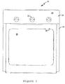
- FIG. 1 the frontal view of an oven body 10 as a representative embodiment of the subject matter front panel 20 is used is given.
- the body 10 has a flange 30 which encircles and supports a cavity (not illustrated in the figure) so as to form the front face of the body; and a front panel 20 which is fixed at the flange 30.
- valve openings 22 are arranged which are in hole-form and which provide a connection to a tap shaft (not illustrated in the figure).
- the lateral panels 40 of the body 10 can be seen.
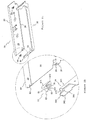
- wings are formed comprising a lower wing 26 and an upper wing 25 which are formed by bending a rectangular flat plate of the front panel 20 vertically about the horizontal axis B1 so as to leave a margin from the upper part and from the lower part along the mutual parallel long edges of the rectangular flat plate.
- the first flap 27 is formed at the upper wing 25 and the second flap 28 is formed at the lower wing 26 by bending two opposite ends of the upper and the lower wings 25, 26 vertically about the vertical axis B2 at a margin from the short edge thereof.
- the upper and the lower wings 25, 26 and the front panel 20 have the form of a U-cross section.
- the first wings 27 are at two opposite ends of the upper wing 25 and they extend parallel to the lateral edge of the front panel 20.
- the second flaps 28 are at two opposite ends of the lower flap 26, and in the same manner, the second flaps 28 extend parallel to the lateral edge of the front panel 20.
- the first and the second flaps 27, 28 are adjacent to a rear surface 23 of the front panel 20.
- the first and the second flaps 27, 28 are aligned with respect to the lateral edge of the front panel 20 as inwardly as their lengths.
- the horizontal bending axis B1 corresponds to the long upper and lower edge of the front panel 20.
- the vertical bending axis B2 extends towards the body 10 so as to be normal to the horizontal bending axis B1 and to the lateral edge of the front panel 20.
- first and the second flaps 27, 28 have a square-like or a rectangular form.
- a connection member (not illustrated in the figure) can reach a lateral wall 32 through the hole 29.
- the lateral wall 32 can be a part of the arm 34 or it can be another extension of the body 10.
- the subject matter front panel 20 is made of a rectangular sheet plate.
- the front panel 20 is first cut inwardly from a corner section of its short edge which is as wide as the width of the flap 27, 28. Afterwards, the parts cut in order to form the flaps 27, 28 are bent about the vertical bending axis B2. After this process, said parts are bent about the horizontal bending axis B1 so that there is a margin from the upper and lower long edges of the front panel 20.
- the valve openings 22 and the hole 29 form existing in the front panel 20 are provided.
- the vertically extending arm 34 with respect to the flange 30 has a front wall 345 and two lateral walls 341, 342 provided so as to define a rectangular cross section whose one long edge is open.
- the end part of the front wall 345 realizes a slight recess inwardly, and on this part, a groove 343 is provided which extends partially towards the ground.
- two arms 34 which correspond mutually to the vertical edges of the front panel 20, extend in the vertical direction upwardly from two ends of the flange 30.
- a connection piece 50 which is used for fixing of the front panel 20 to the flange 30 and which preferably comprises a plastic body 51.
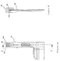
- connection piece 50 comprises an upper channel 53 which extends towards the ground in the same direction of the first flap 27 and which has a width so as to accommodate the first flap 27 with the desired tightness; and a lower channel 52 which extends towards the ground in the same direction as the front wall 345 and which has a width so as to accommodate the front wall 345 with the desired tightness. Accordingly, depending on the positions of the first flap 27 and of the front wall 345, the longitudinal extension directions of the lower and upper channel 52, 53 are essentially parallel to each other and the transversal extension directions thereof are essentially vertical to each other.
- a couple of seating surfaces 55 are provided which are perpendicular to the extension direction of the channel 53 and in other words, which extend mutually and essentially parallel with respect to the ground.
- a support part 54 which is designed in order to provide resistance, extends between the body 51 and the lower part of the channel 53. Said support part 54 is preferably in the form of a bar.
- the support part 54, the seating surfaces 55 and the channel walls 531 defining the upper channel 53 define a Y-like form where the end part of the arms 34 is bent, when viewed frontally.
- the front part of the body 51 defines a handling part 511 which is provided so as to extend in a substantially flat manner towards the front panel 20.
- the body 51 also has a tail part 512 which extends towards the ground at the continuation of the handling part 511.
- the tail part 512 has a form similar to an elongated isosceles trapezoid form and accordingly, the tail part 512 extends so as to widen downwardly and so as to approach the lateral walls 342 of the arm 34. This provides a more stabile connection.
- the connection piece 50 has a lateral cross section similar to an inverse "d".
- connection piece 50 is made of plastic or it can be made of another flexible material or metal like rubber, silica.
- connection piece 50 is preferably held from the handling part 511; and afterwards, the connection piece 50 is set onto the flange 30 so that the lower channel thereof 52 will clasp around the front wall 345 of the arm 3 with respect to the flange 30.
- the front panel 20 is connected to the flange 30 so that the first flap 27 enters into the upper channel 53; and thus a vertical right and left movement of the front panel 20 with respect to the flange 30 is prevented.
- the upper wing's lower surface contacts from above with the connection piece's 50 seating surface 55 facing the inside of the oven.
- the inclined surface 344 which is provided at the upper end of the arm's 34 lateral wall 342 facing outwardly, is aligned with the seating surface 55 on the other side.
Landscapes
- Engineering & Computer Science (AREA)
- Chemical & Material Sciences (AREA)
- Combustion & Propulsion (AREA)
- Mechanical Engineering (AREA)
- General Engineering & Computer Science (AREA)
- Baking, Grill, Roasting (AREA)
- Electric Ovens (AREA)
Claims (12)
- Four comprenant un corps (10) présentant une paroi avant (345) avec une ouverture avant (36) permettant de fournir un accès à un compartiment de cuisson ; un entourage (30) formant la paroi avant (345) ; un panneau avant (20) étant fixé sur l'entourage (30), le panneau avant (20) présentant au moins un premier rabat (27) qui est formé par pliage du panneau avant (20) en direction du corps (10) de manière à former une équerre ; et comprenant une pièce de raccordement (50) permettant de fixer le panneau avant (20) sur l'entourage (30), la pièce de raccordement présentant un canal supérieur (53) permettant d'accueillir ledit premier rabat (27) et présentant un canal inférieur (52) permettant d'accueillir au moins une paroi (341, 342, 345) dudit entourage (30),
caractérisé en ce que
le canal supérieur (53) de la pièce de raccordement (50) est conçu pour restreindre un mouvement du premier rabat (27) dans une direction s'éloignant de l'entourage (30). - Four selon la revendication 1, dans lequel ledit canal supérieur (53) s'étend verticalement dans la même direction que le premier rabat (27), et dans lequel ledit canal supérieur (53) présente une largeur prédéterminée permettant d'accueillir le premier rabat (27) avec un resserrement important.
- Four selon la revendication 1 ou 2, dans lequel ledit canal inférieur (52) s'étend verticalement dans la même direction qu'au moins une paroi (341, 342, 345) de l'entourage (30), et ledit canal inférieur (52) présente une largeur prédéterminée permettant d'accueillir la paroi (341, 342, 345) de l'entourage (30) avec un resserrement important.
- Four selon l'une quelconque des revendications précédentes, dans lequel les canaux inférieur et supérieur (52, 53) sont essentiellement parallèles l'un à l'autre.
- Four selon l'une quelconque des revendications précédentes, dans lequel ladite au moins une paroi de l'entourage (30) est une paroi avant (345) d'un bras (34) qui est fourni au niveau de l'entourage (30) et qui est positionné parallèlement à au moins un bord latéral vertical du panneau avant (20).
- Four selon l'une quelconque des revendications précédentes, dans lequel ladite pièce de raccordement (50) comprend en outre au moins une surface d'assise (55) qui est formée de manière à s'étendre de manière essentiellement parallèle au sol au niveau de l'extrémité du canal supérieur (53) et de manière à faire face à l'aile supérieure (25).
- Four selon l'une quelconque des revendications précédentes, dans lequel ladite pièce de raccordement (50) comprend en outre au moins une pièce de support (54) qui s'étend entre la partie inférieure du canal supérieur (53) et le corps (51) de la pièce de raccordement (50).
- Four selon l'une quelconque des revendications précédentes, dans lequel ladite pièce de raccordement (50) comprend en outre une pièce de manipulation (511) qui s'étend à partir du corps (51) en direction du panneau avant (20).
- Four selon l'une quelconque des revendications précédentes, dans lequel ladite pièce de raccordement (50) est réalisée en plastique.
- Four selon l'une quelconque des revendications précédentes, dans lequel :le panneau avant (20) comprend une aile supérieure (25) pliée horizontalement en direction du corps (10) ;le panneau avant (20) comprend deux premiers rabats (27), au niveau de bords opposés de l'aile supérieure (25), s'étendant verticalement vers le bas ;l'entourage (30) comprend deux bras (34), chaque bras (34) présentant une paroi avant (345) avec une rainure (343), les parois avant (345) faisant face au dessus du panneau avant (20) ;deux pièces de raccordement (50) couplent le panneau avant (20) à l'entourage (30), les pièces de raccordement (50) présentant respectivement une crête se logeant dans la rainure (343) de la paroi avant (345) respective du bras (34).
- Four selon l'une quelconque des revendications précédentes, dans lequel le canal inférieur (52) se serre autour d'un bord de la paroi avant (345) du bras (34).
- Four selon l'une quelconque des revendications précédentes, dans lequel le panneau avant (20) comprend des ouvertures (22) pour un affichage ou des éléments de commande.
Applications Claiming Priority (1)
| Application Number | Priority Date | Filing Date | Title |
|---|---|---|---|
| TR2011/05058A TR201105058A1 (tr) | 2011-05-25 | 2011-05-25 | Ön panele sahip bir fırın. |
Publications (2)
| Publication Number | Publication Date |
|---|---|
| EP2527748A1 EP2527748A1 (fr) | 2012-11-28 |
| EP2527748B1 true EP2527748B1 (fr) | 2016-07-13 |
Family
ID=46149232
Family Applications (1)
| Application Number | Title | Priority Date | Filing Date |
|---|---|---|---|
| EP12169004.4A Active EP2527748B1 (fr) | 2011-05-25 | 2012-05-23 | Four équipé d'un panneau avant |
Country Status (2)
| Country | Link |
|---|---|
| EP (1) | EP2527748B1 (fr) |
| TR (1) | TR201105058A1 (fr) |
Families Citing this family (4)
| Publication number | Priority date | Publication date | Assignee | Title |
|---|---|---|---|---|
| DE102014217635B4 (de) | 2014-09-03 | 2024-05-29 | BSH Hausgeräte GmbH | Haushaltsgerät |
| EP3037733B1 (fr) * | 2014-12-25 | 2019-10-23 | BSH Hausgeräte GmbH | Appareil domestique ayant un élément de support |
| EP3040622B1 (fr) * | 2014-12-29 | 2017-11-22 | BSH Hausgeräte GmbH | Appareil domestique ayant un élément de couplage |
| EP3182019B1 (fr) * | 2015-12-18 | 2019-02-20 | BSH Hausgeräte GmbH | Appareil de cuisson ayant un élément de couplage |
Family Cites Families (6)
| Publication number | Priority date | Publication date | Assignee | Title |
|---|---|---|---|---|
| DE19649047C2 (de) * | 1996-11-27 | 1998-09-10 | Juno Kuechentech Electrolux | Haushaltsgerät mit einer Bedienblende, die mit von vorne nicht sichtbaren Befestigungselementen befestigt ist |
| DE19747769C2 (de) * | 1997-10-29 | 1999-12-16 | Bsh Bosch Siemens Hausgeraete | Haushaltsgerät mit Frontblende |
| DE102007055311A1 (de) * | 2007-11-20 | 2009-05-28 | BSH Bosch und Siemens Hausgeräte GmbH | Bedieneinheit für ein Hausgerät und Verfahren zum Herstellen einer Bedieneinheit |
| KR100938581B1 (ko) | 2007-12-14 | 2010-01-26 | 엘지전자 주식회사 | 오븐 및 오븐의 컨트롤 패널 조립방법 |
| DE102008031246A1 (de) * | 2008-07-02 | 2010-01-07 | BSH Bosch und Siemens Hausgeräte GmbH | Haushaltsgeräteblendenvorrichtung |
| DE102009000650A1 (de) * | 2009-02-06 | 2011-01-27 | BSH Bosch und Siemens Hausgeräte GmbH | Schalterfrontpositionierung |
-
2011
- 2011-05-25 TR TR2011/05058A patent/TR201105058A1/tr unknown
-
2012
- 2012-05-23 EP EP12169004.4A patent/EP2527748B1/fr active Active
Also Published As
| Publication number | Publication date |
|---|---|
| EP2527748A1 (fr) | 2012-11-28 |
| TR201105058A1 (tr) | 2015-05-21 |
Similar Documents
| Publication | Publication Date | Title |
|---|---|---|
| EP2527748B1 (fr) | Four équipé d'un panneau avant | |
| US10208963B2 (en) | Cooking appliance | |
| US20050028805A1 (en) | Door for a household appliance having a removable pane | |
| US9372003B2 (en) | Spring clip attachment for a surface cooking module of a household cooking appliance | |
| AU2008271628B2 (en) | A cooking oven door with a door frame and a door panel | |
| JP4008381B2 (ja) | コンロ用天板 | |
| AU725271B2 (en) | Rack with an upper and bottom frame made from a continuous section | |
| EP1777462A2 (fr) | Porte pour un four cuisinier | |
| EP3495739B1 (fr) | Appareil de cuisson comprenant un système de couplage de cadre avec un meilleur alignement de boutons et procédé de fabrication d'un tel appareil | |
| EP3040622B1 (fr) | Appareil domestique ayant un élément de couplage | |
| US5967634A (en) | Support base for a built-in oven | |
| DE19854229B4 (de) | Kochfeld mit zweiteiligem Rahmen | |
| US20090039750A1 (en) | Adjusting rail | |
| EP1924812B1 (fr) | Dispositif de refroidissement | |
| CN110980487B (zh) | 电梯门套用安装组件及电梯门套组件 | |
| EP3182019B1 (fr) | Appareil de cuisson ayant un élément de couplage | |
| KR100641433B1 (ko) | 전기 오븐 | |
| EP3037733B1 (fr) | Appareil domestique ayant un élément de support | |
| KR200320245Y1 (ko) | 조립식 선반틀 | |
| CN221705585U (zh) | 一种灶面框及集成灶 | |
| CN220069539U (zh) | 烤箱和烤箱灶 | |
| CN220728336U (zh) | 一种取暖器结构 | |
| CN220695214U (zh) | 一种用于清洗机的门体结构及清洗机 | |
| CN220353734U (zh) | 一种门体结构及应用该门体结构的烹饪设备 | |
| EP2174569B1 (fr) | Système modulaire pour mur équipé |
Legal Events
| Date | Code | Title | Description |
|---|---|---|---|
| PUAI | Public reference made under article 153(3) epc to a published international application that has entered the european phase |
Free format text: ORIGINAL CODE: 0009012 |
|
| AK | Designated contracting states |
Kind code of ref document: A1 Designated state(s): AL AT BE BG CH CY CZ DE DK EE ES FI FR GB GR HR HU IE IS IT LI LT LU LV MC MK MT NL NO PL PT RO RS SE SI SK SM TR |
|
| AX | Request for extension of the european patent |
Extension state: BA ME |
|
| 17P | Request for examination filed |
Effective date: 20130528 |
|
| RBV | Designated contracting states (corrected) |
Designated state(s): AL AT BE BG CH CY CZ DE DK EE ES FI FR GB GR HR HU IE IS IT LI LT LU LV MC MK MT NL NO PL PT RO RS SE SI SK SM TR |
|
| RAP1 | Party data changed (applicant data changed or rights of an application transferred) |
Owner name: BSH HAUSGERAETE GMBH |
|
| GRAP | Despatch of communication of intention to grant a patent |
Free format text: ORIGINAL CODE: EPIDOSNIGR1 |
|
| RIC1 | Information provided on ipc code assigned before grant |
Ipc: F24C 7/08 20060101AFI20151215BHEP Ipc: F24C 15/08 20060101ALI20151215BHEP |
|
| INTG | Intention to grant announced |
Effective date: 20160121 |
|
| GRAS | Grant fee paid |
Free format text: ORIGINAL CODE: EPIDOSNIGR3 |
|
| GRAA | (expected) grant |
Free format text: ORIGINAL CODE: 0009210 |
|
| AK | Designated contracting states |
Kind code of ref document: B1 Designated state(s): AL AT BE BG CH CY CZ DE DK EE ES FI FR GB GR HR HU IE IS IT LI LT LU LV MC MK MT NL NO PL PT RO RS SE SI SK SM TR |
|
| REG | Reference to a national code |
Ref country code: GB Ref legal event code: FG4D |
|
| REG | Reference to a national code |
Ref country code: AT Ref legal event code: REF Ref document number: 812659 Country of ref document: AT Kind code of ref document: T Effective date: 20160715 Ref country code: CH Ref legal event code: EP |
|
| REG | Reference to a national code |
Ref country code: IE Ref legal event code: FG4D |
|
| REG | Reference to a national code |
Ref country code: DE Ref legal event code: R096 Ref document number: 602012020363 Country of ref document: DE |
|
| REG | Reference to a national code |
Ref country code: LT Ref legal event code: MG4D |
|
| REG | Reference to a national code |
Ref country code: NL Ref legal event code: MP Effective date: 20160713 |
|
| REG | Reference to a national code |
Ref country code: AT Ref legal event code: MK05 Ref document number: 812659 Country of ref document: AT Kind code of ref document: T Effective date: 20160713 |
|
| PG25 | Lapsed in a contracting state [announced via postgrant information from national office to epo] |
Ref country code: NO Free format text: LAPSE BECAUSE OF FAILURE TO SUBMIT A TRANSLATION OF THE DESCRIPTION OR TO PAY THE FEE WITHIN THE PRESCRIBED TIME-LIMIT Effective date: 20161013 Ref country code: LT Free format text: LAPSE BECAUSE OF FAILURE TO SUBMIT A TRANSLATION OF THE DESCRIPTION OR TO PAY THE FEE WITHIN THE PRESCRIBED TIME-LIMIT Effective date: 20160713 Ref country code: FI Free format text: LAPSE BECAUSE OF FAILURE TO SUBMIT A TRANSLATION OF THE DESCRIPTION OR TO PAY THE FEE WITHIN THE PRESCRIBED TIME-LIMIT Effective date: 20160713 Ref country code: IT Free format text: LAPSE BECAUSE OF FAILURE TO SUBMIT A TRANSLATION OF THE DESCRIPTION OR TO PAY THE FEE WITHIN THE PRESCRIBED TIME-LIMIT Effective date: 20160713 Ref country code: HR Free format text: LAPSE BECAUSE OF FAILURE TO SUBMIT A TRANSLATION OF THE DESCRIPTION OR TO PAY THE FEE WITHIN THE PRESCRIBED TIME-LIMIT Effective date: 20160713 Ref country code: IS Free format text: LAPSE BECAUSE OF FAILURE TO SUBMIT A TRANSLATION OF THE DESCRIPTION OR TO PAY THE FEE WITHIN THE PRESCRIBED TIME-LIMIT Effective date: 20161113 Ref country code: NL Free format text: LAPSE BECAUSE OF FAILURE TO SUBMIT A TRANSLATION OF THE DESCRIPTION OR TO PAY THE FEE WITHIN THE PRESCRIBED TIME-LIMIT Effective date: 20160713 Ref country code: RS Free format text: LAPSE BECAUSE OF FAILURE TO SUBMIT A TRANSLATION OF THE DESCRIPTION OR TO PAY THE FEE WITHIN THE PRESCRIBED TIME-LIMIT Effective date: 20160713 |
|
| PG25 | Lapsed in a contracting state [announced via postgrant information from national office to epo] |
Ref country code: GR Free format text: LAPSE BECAUSE OF FAILURE TO SUBMIT A TRANSLATION OF THE DESCRIPTION OR TO PAY THE FEE WITHIN THE PRESCRIBED TIME-LIMIT Effective date: 20161014 Ref country code: SE Free format text: LAPSE BECAUSE OF FAILURE TO SUBMIT A TRANSLATION OF THE DESCRIPTION OR TO PAY THE FEE WITHIN THE PRESCRIBED TIME-LIMIT Effective date: 20160713 Ref country code: ES Free format text: LAPSE BECAUSE OF FAILURE TO SUBMIT A TRANSLATION OF THE DESCRIPTION OR TO PAY THE FEE WITHIN THE PRESCRIBED TIME-LIMIT Effective date: 20160713 Ref country code: BE Free format text: LAPSE BECAUSE OF FAILURE TO SUBMIT A TRANSLATION OF THE DESCRIPTION OR TO PAY THE FEE WITHIN THE PRESCRIBED TIME-LIMIT Effective date: 20160713 Ref country code: PT Free format text: LAPSE BECAUSE OF FAILURE TO SUBMIT A TRANSLATION OF THE DESCRIPTION OR TO PAY THE FEE WITHIN THE PRESCRIBED TIME-LIMIT Effective date: 20161114 Ref country code: LV Free format text: LAPSE BECAUSE OF FAILURE TO SUBMIT A TRANSLATION OF THE DESCRIPTION OR TO PAY THE FEE WITHIN THE PRESCRIBED TIME-LIMIT Effective date: 20160713 Ref country code: AT Free format text: LAPSE BECAUSE OF FAILURE TO SUBMIT A TRANSLATION OF THE DESCRIPTION OR TO PAY THE FEE WITHIN THE PRESCRIBED TIME-LIMIT Effective date: 20160713 Ref country code: PL Free format text: LAPSE BECAUSE OF FAILURE TO SUBMIT A TRANSLATION OF THE DESCRIPTION OR TO PAY THE FEE WITHIN THE PRESCRIBED TIME-LIMIT Effective date: 20160713 |
|
| REG | Reference to a national code |
Ref country code: DE Ref legal event code: R097 Ref document number: 602012020363 Country of ref document: DE |
|
| PG25 | Lapsed in a contracting state [announced via postgrant information from national office to epo] |
Ref country code: RO Free format text: LAPSE BECAUSE OF FAILURE TO SUBMIT A TRANSLATION OF THE DESCRIPTION OR TO PAY THE FEE WITHIN THE PRESCRIBED TIME-LIMIT Effective date: 20160713 Ref country code: EE Free format text: LAPSE BECAUSE OF FAILURE TO SUBMIT A TRANSLATION OF THE DESCRIPTION OR TO PAY THE FEE WITHIN THE PRESCRIBED TIME-LIMIT Effective date: 20160713 |
|
| PLBE | No opposition filed within time limit |
Free format text: ORIGINAL CODE: 0009261 |
|
| STAA | Information on the status of an ep patent application or granted ep patent |
Free format text: STATUS: NO OPPOSITION FILED WITHIN TIME LIMIT |
|
| PG25 | Lapsed in a contracting state [announced via postgrant information from national office to epo] |
Ref country code: BG Free format text: LAPSE BECAUSE OF FAILURE TO SUBMIT A TRANSLATION OF THE DESCRIPTION OR TO PAY THE FEE WITHIN THE PRESCRIBED TIME-LIMIT Effective date: 20161013 Ref country code: SM Free format text: LAPSE BECAUSE OF FAILURE TO SUBMIT A TRANSLATION OF THE DESCRIPTION OR TO PAY THE FEE WITHIN THE PRESCRIBED TIME-LIMIT Effective date: 20160713 Ref country code: CZ Free format text: LAPSE BECAUSE OF FAILURE TO SUBMIT A TRANSLATION OF THE DESCRIPTION OR TO PAY THE FEE WITHIN THE PRESCRIBED TIME-LIMIT Effective date: 20160713 Ref country code: SK Free format text: LAPSE BECAUSE OF FAILURE TO SUBMIT A TRANSLATION OF THE DESCRIPTION OR TO PAY THE FEE WITHIN THE PRESCRIBED TIME-LIMIT Effective date: 20160713 Ref country code: DK Free format text: LAPSE BECAUSE OF FAILURE TO SUBMIT A TRANSLATION OF THE DESCRIPTION OR TO PAY THE FEE WITHIN THE PRESCRIBED TIME-LIMIT Effective date: 20160713 |
|
| 26N | No opposition filed |
Effective date: 20170418 |
|
| PG25 | Lapsed in a contracting state [announced via postgrant information from national office to epo] |
Ref country code: LU Free format text: LAPSE BECAUSE OF NON-PAYMENT OF DUE FEES Effective date: 20170531 Ref country code: SI Free format text: LAPSE BECAUSE OF FAILURE TO SUBMIT A TRANSLATION OF THE DESCRIPTION OR TO PAY THE FEE WITHIN THE PRESCRIBED TIME-LIMIT Effective date: 20160713 |
|
| REG | Reference to a national code |
Ref country code: DE Ref legal event code: R119 Ref document number: 602012020363 Country of ref document: DE |
|
| REG | Reference to a national code |
Ref country code: CH Ref legal event code: PL |
|
| GBPC | Gb: european patent ceased through non-payment of renewal fee |
Effective date: 20170523 |
|
| PG25 | Lapsed in a contracting state [announced via postgrant information from national office to epo] |
Ref country code: MC Free format text: LAPSE BECAUSE OF FAILURE TO SUBMIT A TRANSLATION OF THE DESCRIPTION OR TO PAY THE FEE WITHIN THE PRESCRIBED TIME-LIMIT Effective date: 20160713 |
|
| REG | Reference to a national code |
Ref country code: IE Ref legal event code: MM4A |
|
| PG25 | Lapsed in a contracting state [announced via postgrant information from national office to epo] |
Ref country code: LI Free format text: LAPSE BECAUSE OF NON-PAYMENT OF DUE FEES Effective date: 20170531 Ref country code: CH Free format text: LAPSE BECAUSE OF NON-PAYMENT OF DUE FEES Effective date: 20170531 |
|
| REG | Reference to a national code |
Ref country code: FR Ref legal event code: ST Effective date: 20180131 |
|
| PG25 | Lapsed in a contracting state [announced via postgrant information from national office to epo] |
Ref country code: LU Free format text: LAPSE BECAUSE OF NON-PAYMENT OF DUE FEES Effective date: 20170523 |
|
| PG25 | Lapsed in a contracting state [announced via postgrant information from national office to epo] |
Ref country code: DE Free format text: LAPSE BECAUSE OF NON-PAYMENT OF DUE FEES Effective date: 20171201 Ref country code: IE Free format text: LAPSE BECAUSE OF NON-PAYMENT OF DUE FEES Effective date: 20170523 Ref country code: GB Free format text: LAPSE BECAUSE OF NON-PAYMENT OF DUE FEES Effective date: 20170523 |
|
| PG25 | Lapsed in a contracting state [announced via postgrant information from national office to epo] |
Ref country code: FR Free format text: LAPSE BECAUSE OF NON-PAYMENT OF DUE FEES Effective date: 20170531 |
|
| PG25 | Lapsed in a contracting state [announced via postgrant information from national office to epo] |
Ref country code: MT Free format text: LAPSE BECAUSE OF NON-PAYMENT OF DUE FEES Effective date: 20170523 |
|
| PG25 | Lapsed in a contracting state [announced via postgrant information from national office to epo] |
Ref country code: AL Free format text: LAPSE BECAUSE OF FAILURE TO SUBMIT A TRANSLATION OF THE DESCRIPTION OR TO PAY THE FEE WITHIN THE PRESCRIBED TIME-LIMIT Effective date: 20160713 |
|
| PG25 | Lapsed in a contracting state [announced via postgrant information from national office to epo] |
Ref country code: HU Free format text: LAPSE BECAUSE OF FAILURE TO SUBMIT A TRANSLATION OF THE DESCRIPTION OR TO PAY THE FEE WITHIN THE PRESCRIBED TIME-LIMIT; INVALID AB INITIO Effective date: 20120523 |
|
| PG25 | Lapsed in a contracting state [announced via postgrant information from national office to epo] |
Ref country code: CY Free format text: LAPSE BECAUSE OF NON-PAYMENT OF DUE FEES Effective date: 20160713 |
|
| PG25 | Lapsed in a contracting state [announced via postgrant information from national office to epo] |
Ref country code: MK Free format text: LAPSE BECAUSE OF FAILURE TO SUBMIT A TRANSLATION OF THE DESCRIPTION OR TO PAY THE FEE WITHIN THE PRESCRIBED TIME-LIMIT Effective date: 20160713 |
|
| PGFP | Annual fee paid to national office [announced via postgrant information from national office to epo] |
Ref country code: TR Payment date: 20250515 Year of fee payment: 14 |