EP2527802A1 - Dispositif et procédé de détermination de caractéristiques de milieux et de récipients - Google Patents
Dispositif et procédé de détermination de caractéristiques de milieux et de récipients Download PDFInfo
- Publication number
- EP2527802A1 EP2527802A1 EP11167953A EP11167953A EP2527802A1 EP 2527802 A1 EP2527802 A1 EP 2527802A1 EP 11167953 A EP11167953 A EP 11167953A EP 11167953 A EP11167953 A EP 11167953A EP 2527802 A1 EP2527802 A1 EP 2527802A1
- Authority
- EP
- European Patent Office
- Prior art keywords
- echo
- echoes
- container
- filling material
- self
- Prior art date
- Legal status (The legal status is an assumption and is not a legal conclusion. Google has not performed a legal analysis and makes no representation as to the accuracy of the status listed.)
- Granted
Links
Images





Classifications
-
- G—PHYSICS
- G01—MEASURING; TESTING
- G01F—MEASURING VOLUME, VOLUME FLOW, MASS FLOW OR LIQUID LEVEL; METERING BY VOLUME
- G01F23/00—Indicating or measuring liquid level or level of fluent solid material, e.g. indicating in terms of volume or indicating by means of an alarm
- G01F23/80—Arrangements for signal processing
-
- G—PHYSICS
- G01—MEASURING; TESTING
- G01F—MEASURING VOLUME, VOLUME FLOW, MASS FLOW OR LIQUID LEVEL; METERING BY VOLUME
- G01F23/00—Indicating or measuring liquid level or level of fluent solid material, e.g. indicating in terms of volume or indicating by means of an alarm
- G01F23/22—Indicating or measuring liquid level or level of fluent solid material, e.g. indicating in terms of volume or indicating by means of an alarm by measuring physical variables, other than linear dimensions, pressure or weight, dependent on the level to be measured, e.g. by difference of heat transfer of steam or water
- G01F23/28—Indicating or measuring liquid level or level of fluent solid material, e.g. indicating in terms of volume or indicating by means of an alarm by measuring physical variables, other than linear dimensions, pressure or weight, dependent on the level to be measured, e.g. by difference of heat transfer of steam or water by measuring the variations of parameters of electromagnetic or acoustic waves applied directly to the liquid or fluent solid material
-
- G—PHYSICS
- G01—MEASURING; TESTING
- G01S—RADIO DIRECTION-FINDING; RADIO NAVIGATION; DETERMINING DISTANCE OR VELOCITY BY USE OF RADIO WAVES; LOCATING OR PRESENCE-DETECTING BY USE OF THE REFLECTION OR RERADIATION OF RADIO WAVES; ANALOGOUS ARRANGEMENTS USING OTHER WAVES
- G01S13/00—Systems using the reflection or reradiation of radio waves, e.g. radar systems; Analogous systems using reflection or reradiation of waves whose nature or wavelength is irrelevant or unspecified
- G01S13/02—Systems using reflection of radio waves, e.g. primary radar systems; Analogous systems
- G01S13/06—Systems determining position data of a target
- G01S13/08—Systems for measuring distance only
-
- G—PHYSICS
- G01—MEASURING; TESTING
- G01S—RADIO DIRECTION-FINDING; RADIO NAVIGATION; DETERMINING DISTANCE OR VELOCITY BY USE OF RADIO WAVES; LOCATING OR PRESENCE-DETECTING BY USE OF THE REFLECTION OR RERADIATION OF RADIO WAVES; ANALOGOUS ARRANGEMENTS USING OTHER WAVES
- G01S15/00—Systems using the reflection or reradiation of acoustic waves, e.g. sonar systems
- G01S15/02—Systems using the reflection or reradiation of acoustic waves, e.g. sonar systems using reflection of acoustic waves
- G01S15/06—Systems determining the position data of a target
- G01S15/08—Systems for measuring distance only
-
- G—PHYSICS
- G06—COMPUTING OR CALCULATING; COUNTING
- G06F—ELECTRIC DIGITAL DATA PROCESSING
- G06F17/00—Digital computing or data processing equipment or methods, specially adapted for specific functions
- G06F17/10—Complex mathematical operations
- G06F17/11—Complex mathematical operations for solving equations, e.g. nonlinear equations, general mathematical optimization problems
Definitions
- the present invention relates to level measurement.
- the invention relates to a level measuring device for determining the position of a filling level of a filling material and / or a separating layer between two contents in a container for determining media and container properties in the measurement of levels of all kinds, a corresponding method, a program element and a computer-readable medium ,
- the signal generated by the level measuring device When using acoustic or optical waves, the signal generated by the level measuring device generally propagates freely in the direction of the product surface to be measured.
- both a free propagation in the direction of the medium to be measured comes into consideration, as well as a propagation inside a waveguide, which leads the radar waves from the level gauge to the medium.
- the high-frequency signals are guided along a waveguide towards the medium.
- the incoming signals On the surface of the medium or medium to be measured, a part of the incoming signals is reflected, and after a suitable period returns to the level measuring device.
- the non-reflected signal components penetrate into the medium, and propagate in accordance with the physical properties of the medium in this further in the direction of the container bottom. At the bottom of the tank, these signals are reflected, and get back to the level gauge after passage of the medium and the superimposed atmosphere.
- the level measuring device receives the signals reflected at various points and determines therefrom according to known methods, the distance to the medium.
- the specific distance to the product is provided to the outside.
- the provision can be realized in analogue form (4..20 mA interface) or also in digital form (fieldbus).
- the signal used for the measurement on the way from the level gauge to the product surface is normally in the range of influence of another medium, which is to be referred to as superimposing medium.
- This overlay medium is located between the level gauge and the surface of the medium to be measured, and is generally represented by a liquid or gaseous atmosphere.
- level measuring device for determining the position of a filling level of a filling material and / or a separating layer between two filling goods, such as may be located in a container
- a method for determining the position of a filling level of a filling material and / or a separating layer between two contents a program element and a computer readable medium according to specified the features of the independent claims.
- a level measuring device for determining the position of a filling level of a filling material and / or a separating layer between two filling products (for example in a container) is specified.
- the fill level measuring device has an echo curve detection device for detecting at least one echo curve, an echo identification device for identifying at least two echoes in one or more of the detected echo curves, and a speed determination device for determining velocity values of the at least two echoes.
- a self-learning device is provided, which is designed for the automatic determination of a characteristic which relates to the dome shaft length of a dome shaft of the container, the container height of the container, the permeability number of a product and / or the permittivity number of a product.
- the self-learning device is designed to determine the characteristic value using at least one of the determined speed values of the echoes.
- the self-learning device may calculate the dome shaft length, the tank height, the permeability number of one or more of the contents, and / or the permittivity of the one or more of the contents.
- a Mehrfachechoerkennungs With respect to another aspect of the invention, a Mehrfachechoerkennungs adopted classify at least one echo of a multiple reflection on a Browngutober Phantom a filling, an impurity and / or on a container bottom of the container in the echo curve as Mehrfachecho.
- the self-learning device is designed to use at least one speed value of a multiple echo classified by the multiple echo recognition device for determining the characteristic value.
- a Bodenechoerkennungs adopted for classifying at least one echo of a reflection at an impurity and / or a container bottom in the echo curve be carried out as a bottom echo, wherein the self-learning device for using at least one speed value of a classified by the bottom echo recognition device ground echo or Trenn Anlagenechos is designed to determine the characteristic value.
- the self-learning device for determining the container height of the container from an intersection of a velocity vector of Greptechos and a velocity vector of a ground echo is executed.
- the self-learning device for determining the dome shaft length of the container can be designed from at least one point of intersection of the velocity vectors of at least two multiple echoes.
- the self-learning device for determining the permittivity number of the filling material and / or a further medium in the container can be designed based on the speed values of the at least two echoes.
- the self-learning device for determining the permittivity number of the filling material and / or another medium in the container is designed based on the positions of the at least two echoes.
- the level measuring device for determining the permittivity number and the permeability of the filling material and / or a further medium in the container can be designed on the basis of a single transit time measurement.
- a method for determining the position of a filling level, a filling material and / or a separating layer between two contents, for example in a container, indicated in the first at least one echo curve is detected and then one or more echoes in one or more of the detected echo curves.
- one or more characteristic values which are a dome shaft length, a tank height, a permeability number of a filling material or a permittivity number of a filling material, are determined. At least one of the determined speed values of the echoes is used for this determination.
- a program element is specified which, when executed on a processor of a level gauge, the Instructs the processor to perform the steps described above and / or below.
- a computer readable medium for storing a program element that, when executed on a processor of a level gauge, instructs the processor to perform the steps described above and / or below.
- the program element (called computer program element) may be part of a software that is stored on a processor of the level gauge.
- the processor can also be the subject of the invention.
- this aspect of the invention comprises a computer program element which already uses the invention from the beginning, as well as a computer program element which by means of an update causes an existing program for the use of the invention.
- bottom echo is synonymous with a multiple echo 0th order of ground reflection.
- the position of a Medgutober Formation may be in connection with a separation layer measurement in particular the position of a release layer between two different media or products, which is identical to the position of the product surface of the lower of the two contents or media in a container for interface measurement.
- various methods can be used, after which the position of a product surface in a container can be determined.
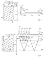
- FIG. 1 shows an arrangement for level measurement.
- the container 100 is filled with a liquid 106 up to a filling level d B - d L.
- the space 107 above the liquid is filled, for example, with air.
- the liquid is covered with air as an overlay medium.
- the fill level measuring device 101 generates an electromagnetic pulse 103 with the aid of a high-frequency device 102 and couples it into a suitable antenna 104, whereupon this pulse propagates approximately at the speed of light in the direction of the product surface 105 to be measured.
- the product surface 105 reflects part of the incoming signal energy, whereupon the reflected signal component propagates back to the level meter 101.
- the unreflected signal component penetrates into the liquid 106, and propagates therein at a greatly reduced speed in the direction of the container bottom.
- c 0 describes the speed of light in a vacuum
- ⁇ M the permittivity of the liquid
- ⁇ M the permeability of the liquid.
- the incoming signals are processed by means of the radio-frequency device 102, and preferably transformed into a low-frequency intermediate frequency range.
- the analogue echo curves which are provided by the high-frequency device 102, are digitized and made available to an evaluation device 111.
- the abovementioned components which are used to provide a digitized echo curve may for example define an echo curve detection device.
- the evaluation device 111 analyzes the digitized echo curve, and determines, based on the echoes contained therein, according to known methods, that echo which was generated by the reflection at the product surface 105. In addition, the evaluation determines the exact electrical distance up to this echo. Furthermore, the determined electrical distance to the echo is corrected in such a way that influences of the overlay medium 107 on the propagation of the electromagnetic waves are compensated. The thus calculated, compensated distance to the filling material is transferred to an output device 112, which further processes the determined value according to the specifications of the user, for example by linearization, offset correction, conversion into a filling level d B - d L. The prepared measured value is provided to an external communication interface 113 to the outside. All established interfaces can be used here, 4..20 mA in particular - Current interfaces, industrial fieldbuses such as HART, Profibus, FF, or even computer interfaces such as RS232, RS485, USB, Ethernet, FireWire.
- FIG. 2 illustrates again in detail important steps that can be used in the evaluation device 111 to compensate for the influences of various media in the context of echo signal processing.
- the curve 201 firstly shows the echo curve 204 detected by the analog-to-digital converter unit 110 over time.
- the echo curve initially contains the portion of the transmission pulse 205 reflected within the antenna.
- a first echo 206 is detected at the time t L , which is caused by the reflection of signal components at the interface 105 or surface 105 of the medium 106 in the container.
- Another echo 207 arises as the first multiple echo of the Greerute echoes 206, and is detected at time t ML .
- the signal components entering the medium 106 are reflected on the container bottom 108 after passing through the product 106, and produce a further echo 208 within the echo curve 204.
- This bottom echo 208 is detected at the time t B.
- a multiple echo 209 of the ground echo may be detected.
- the time-dependent curve 201 is transformed into a distance-dependent curve 202.
- the ordinate of the representation 201 is converted into a distance axis by multiplication with the speed of light in a vacuum.
- the echo 205 caused by the antenna 104 receives the distance value 0m.
- the distance values are multiplied by the factor 0.5, twice the way to the Product surface and back to compensate.
- the second representation 202 shows the echo curve as a function of the electrical distance D.
- the electrical distance corresponds to half the distance that an electromagnetic wave covers in a vacuum in a certain time.
- the electrical distance does not take into account any influences of a medium, which possibly lead to a slower preparation of the electromagnetic waves.
- Curve 202 thus represents an uncompensated, but location-related echo curve.
- the third representation 203 shows a fully compensated echo curve 211.
- the influence of the overlay medium 107 in the region between the locations 0 and D L (curve 202) must be taken into account in the present case.
- the third representation 203 finally shows the corrected course. Both the distance to the echo 206 of the product surface 105 and the distance to the echo 208 generated by the container bottom 108 coincide with the distances measurable on the container 109. The distance to the Mehrfachecho 207 of the product surface can not be measured directly on the container, since the above compensation is only valid for direct reflections. The same applies to the multiple echo 209 of the reflection at the container bottom 108.
- FIG. 3 illustrates the use of an indirect or indirect determination of the position of the product surface on the basis of a ground echo.
- the illustrated container 301 is almost completely filled with the filling material 302.
- the level gauge 101 in the container 301 of the FIG. 3 be mounted in a dome shaft 303.
- a manhole may be a shaft through which the tank can be filled.
- a manhole may also be realized by a boarding possibility for operating personnel, a so-called manhole. It also likes it be possible to use a dome shaft for other purposes.
- the level gauge can be attached.
- the echo curve 304 detected by the level measuring device 101 has, in addition to the echo 305 generated by the antenna 104, only a multiple reflection E ML1 306 of the product surface 307 and the bottom echo 309 generated by the container bottom 308.
- the echo generated by the surface 307 of the medium can not be reliably detected on the basis of the detected echo curve 304, since it is completely covered by the antenna echo 305 in the area of influence of the antenna echo 305.
- the distance d L to the product surface can not be determined.
- the bottom echo 309 in the echo curve can no longer be detected.
- multiple and bottom echoes can be detected by analyzing the velocity values and / or the positions of multiple echoes of an echo curve.
- a fundamental requirement for carrying out an indirect measurement is the knowledge of the permittivity and permeability of the media contained in the container 301 as well as the knowledge of the geometric dimensions of the container, in particular the dowel shaft length d D and the extended container height d B or the container height d b - d D ,
- FIG. 4 illustrates the physical relationships that may lead to the formation of multiple echoes.
- the fill level measuring device 401 generates an electromagnetic pulse 402 according to known methods and sends it out in the direction of the product surface 105 to be measured.
- Signal arrow 403 outlines the propagation of the signal as a function of physical distance over time.
- Signal path 404 illustrates this propagation path. Due to the received signals, the filling level measuring device forms an echo curve 204, which has a first echo E L 206 due to the signal paths 403 and 404.
- a portion of the signals is reflected again, for example, on the container ceiling 405 or on the level gauge 401, and propagates in the direction of the product surface 105, which is indicated by the signal arrow 406.
- This signal component is redone from the product surface reflected, and passes after a corresponding period back to the level measuring device 401, where it is detected as the first multiple echo E ML 1 207 of the Golfgutreflexion and mapped to the echo curve 204.
- Signal path 407 illustrates the process.
- the signal is reflected, and passes to the appropriate Running time back to the level gauge.
- the signal paths 409 and 410 illustrate the propagation of the signal on this path. It should be noted that the signal propagates in the different media at different speeds, which can be seen in the signal path diagram by different slopes of the signal paths 409, 410.
- the fill level measuring device receives the signal portions reflected from the container bottom, and images these in the form of a bottom echo E B 208 in the echo curve 204.
- the signal paths 411, 412, 413, 414 illustrate the occurrence of a first multiple echo E MB 1 209 of the ground echo E B 208, which is also reflected in the echo curve 204 received by the level measuring device after a corresponding transit time.
- the Signalpfaddiagramn shows this the signal paths 417 and 418, which are suitable to produce a Mehrfachecho E ML 2 415 second order based on the reflection of the product surface. Corresponding multiple echoes of higher order are also possible for the reflection of the container bottom. It may not be a problem for a person skilled in the art to apply multiple echoes to the aspects of the present invention, which are represented below by means of the first-order multiple echoes to transfer higher order.
- the order of a multiple echo is defined as the number of reflections of a transmitted signal at a media surface of a product to be measured in the container, reduced by 1.
- the echo E L is identical to a multiple echo 0th order according to this nomenclature, whereas the echo E ML 1 is identical a multiple echo of 1st order.
- mixed signal paths are also conceivable, which lead to further echoes within the received echo curves.
- the signal may be possible for the signal to enter the medium after passing through the signal path 406 and to propagate toward the container bottom.
- part of the signal energy is reflected after passing through the signal path 411 of the product surface, and again propagates directly in the direction of the level gauge.
- Mixed signal paths should not be considered further in the context of the present invention, since they play almost no role in practical application. However, it may not be difficult for a person skilled in the art to translate the aspects of the present invention, which are presented below on the basis of the first-order multiple echoes, to mixed multiple echoes.
- mixed multiple echoes are defined as echoes of an echo curve, which are caused by signal paths within which a signal generated by the level measuring device is reflected at at least two different boundary surfaces of at least one filling substance to be measured in a container. This example does not contain mixed multiple echo.
- FIG. 5 shows an example of the use of the measuring device according to the invention 401 in such a container 501.
- the level gauge is not mounted directly on the level of the container ceiling 502, but is located in a manhole 503, which in Contrary to example FIG. 4 here has a physical length of d D > 0.
- the mounting position of the level gauge in the dome shaft affects the formation of multiple echoes massively.
- the signal path diagram 504 illustrates the formation of multiple echoes in the present case.
- the signal generated by the level meter initially propagates through the manhole 503 and the actual container towards the surface of the medium 505.
- Signal path 506 illustrates this signal path.
- the medium reflects the signal, whereupon it propagates in the direction of the level gauge 401. Since the opening 513 of the dome shaft 503 is small in relation to the container ceiling 502, only a very small part of the signal is displayed as a level echo E L 515 on the echo curve 514.
- the signal paths 507 and 508 illustrate this propagation path. The far greater part of the signal energy is reflected at the container ceiling (signal path 509), and reaches the product surface again. In this way, after passage of the signal paths 509, 510, and 511, a first multiple echo E ML 1 516 is formed on the echo curve.
- the presented relationships for dome shafts apply correspondingly to the multiple echoes of higher order, which is indicated by the signal path 512, but also for the multiple echoes of the ground reflection.
- FIG. 6 shows an associated use case.
- the level gauge 401 is mounted above an open-topped container 601, wherein the entire measuring arrangement is, for example, in a hall, so that above the arrangement, a metallic flat roof 602 may be located.
- the distance of the reference plane 603 of the level measuring device 401 from the hall roof 602 is in the course of the signal processing of the level gauge 401 as a negative dome shaft length with a physical length of d D ⁇ 0 considered.
- the application may therefore in the context of the present invention have a dome shaft, this may have a negative length may. If measurements are now made by the level measuring device 401, signal paths as shown in the signal path diagram 604 result.
- the direct reflection of the product surface which is illustrated by the signal paths 605 and 606, is reflected in the echo curve as a level echo E L 610.
- the far greater part of the signal energy propagates up to the hall roof 602, is reflected by this and, after renewed reflection at the product surface, leads to the first multiple echo E ML 1 611 within the echo curve 612.
- the signal propagation which leads to this echo is achieved the signal paths 607, 608 and 609 indicated.
- the automated determination of the container height is only possible if in addition to the permittivity of the media in the container, the length of a possibly existing dome shaft is known in advance.
- FIG. 7 shows an example of level gauge and a device for determining media and container properties according to an embodiment of the invention.
- the level gauge 701 corresponds in many parts to the in FIG. 1 Level meter 101 shown, however, differs by a modified evaluation device 702 from the previously used devices.
- the evaluation device 702 may include or consist of an echo identification device 7021, a tracking device 7022, a speed determination device 7023, a multiple and bottom echo recognition device 7024, a decision device 7025, an echo measurement device 7026 and a self-learning device 7027.
- the echo identification device 7021 examines the echo curve transmitted by the echo curve detection device 102, 110 for echoes 205, 206, 207, 208, 209 contained therein.
- the tracking device 7022 carries out a grouping of echoes from different measurement cycles in such a way that echoes originating from the same reflection point in the Container caused, and which arise due to the same signal paths, are grouped together. On the basis of these groups, also called tracks, for example, the speed of an echo can be reliably determined.
- the speed determination device 7023 determines at least one index of the speed of the echoes of the current echo curve.
- the multiple and bottom echo recognition device 7024 classifies multiple echoes and ground echoes.
- the self-learning device 7027 may be able to automatically learn media and container properties based on the identified echoes, tracks, and the classification of ground and multiple echoes.
- the decision device 7025 may make a decision on the basis of all previously determined values as to which echo of the echo curve was generated by the product reflection.
- the exact position of the echo can be determined, for example by the use of automatically acquired characteristic values of a medium or of a container in the context of an indirect measurement. Furthermore, influences of a superposition medium can be compensated.
- a sequence of measuring cycles is shown, as can be performed with a measuring device 701 according to the invention.
- the container 109 to be monitored is initially filled with a medium 106 at continuous times t 0 ⁇ t 1 ⁇ t 2 ⁇ t 3 ⁇ t 4 ⁇ t 5 , and then emptied again.
- the echo curves 801, 802, 803, 804, 805, 806 detected by a fill level measuring device 701 according to the invention at the respective times are sketched directly next to the representation of the container at the respective point in time.
- the echo curve 801 of the empty container 109 has, in addition to the echo E 1 807, only an echo E 2 808 caused by the ground and a further multiple echo E 3 809 of the ground reflection. These echoes are detected by the echo identification device, whereby no classification of the echoes takes place at this time.
- the echoes are therefore preferably provided with different indices in order to be able to process them algorithmically.
- the tracking device 7022 attempts in a further processing step to place the identified echoes in a logical relationship with echoes previously identified. Disclosures for carrying out a tracking method in the context of level measurement technology can be found, for example, in WO 2009/037000 , The tracking device 7022 of the level measuring device 701 may, based on the antenna reflection E 1, initialize a first track T 0 831.
- the container may be slightly filled.
- the detected by the level gauge echo curve 802 is in the FIG. 8 shown.
- the tracking unit of the level gauge 701 sets the already started tracks T 0 831, T 3 834 and T 4 835 with the echoes of the current measurement originating from the same reflection point in the container. Furthermore, a new track T 1 832 is initialized to monitor the newly added level echo E 5 812.
- the newly added multiple reflection of the product surface leads to the reinitialization of a track T 2 833, whereas the already existing tracks T 0 831, T 1 832, T 3 834 and T 4 835 are continued with the echoes of the respectively identical reflection point in the container.
- the tracking method is able to account for the lack of this echo, for example by inserting an invisible link 836 within track T 4 835.
- the other tracks are augmented with the detected echoes of echo curve 804 as described above.
- a track list is provided in the sensor, which is provided by the tracking device 7022 and which describes the current tracks 83 at the respective time .
- the track list may consist of vectors which describe the locations of the respectively associated echo for each track.
- a memory-optimized representation such as in EP 2 309 235 A1 is described.
- the method proposed there also provides a possibility of subdividing a track, that is to say a sequence of echoes having an identical origin of reflection, into temporal sections in which the associated echo has an almost constant speed.
- an analysis based on the tracks 831, 832, 833, 834, 835 is carried out on multiple and bottom echoes.
- a classification of the detected echoes may be made such that the echoes of the track T 2 833 are multiple echoes of the respective echoes of the track T 1 832 because track T 2 moves smoothly in the identical direction as track T 1 .
- it may be classified from the multiple echo and ground echo recognition 7024 that the echoes of the track T 3 describe the bottom of the container as they move in push-pull to the direction of movement of the level echoes of the track T 1 .
- the velocities of the respective echoes can be determined on the basis of the local slope of the associated tracks T 2 832 and T 3 834.
- multiple positions of the echoes of a track can also be used to determine the speed of an echo. However, it may also be possible to determine the speed for entire sections of a track in which the speed of the echoes is almost constant. This in EP 2 309 235 A1 described method can be used to transfer a track in sections of constant speeds.
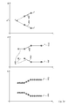
- the tracks may be transferred to track segments 904.
- the segments are formed in such a way that measurements in which the echoes of a track move at (approximately) constant speed or the same velocity vector can be represented by a mathematical straight line equation or by two support points 905, 906 in a memory-optimized manner. Disclosures for carrying out this step can be found, for example, in EP 2 309 235 A1 ,
- the fill level measuring device can use the self-learning device 7027 to identify at least one segment pair 907, 908 valid in the same time period, which is caused on the one hand by the same reflection point in the container, ie a multiple echo attraction has, and which at the same time each has a significant slope greater than zero.
- the slope of a segment may be equivalent to the velocity of the echoes underlying the segment.
- the identified segment pair 907, 908 is further examined within the self-learning device.
- the mathematical straight-line equations of the selected segments are determined in order to calculate the intersection point S of the two straight lines on the basis of these equations according to known methods.
- the distance D at which the two straight lines intersect corresponds to the dome shaft length D D of the container currently to be measured.
- the electrical dome shaft length corresponds to a good approximation of the physical dome shaft length.
- the above illustration of a preferred embodiment illustrates the mode of operation of the method on the basis of the formation of track and track segments.
- the principle of the disclosed invention can also be implemented on the basis of individual echoes which have been recognized by a classification device as multiple echoes.
- the mathematical straight-line equations describe the current velocity vector of the respective echoes, and in this case are defined by the fact that the straight lines must run through the current point of the respective echo, which may be defined by the respective position and the current point in time. Furthermore, the slope of the respective straight line is identical to current speed of the respective echo.
- the linear equations are thus exactly defined, and allow the mathematical calculation of the intersection S as already disclosed above.
- the speed of an echo can be easily determined from the local slope of the associated tracks.
- the speed can be determined from a position shift of two echoes of a track.
- multiple positions of the echoes of a track can also be used to determine the speed of an echo.
- the tracks may be transferred to track segments 1003.
- the segments are formed in such a way that measurements in which the echoes of a track move at (approximately) constant speed or the same velocity vector can be represented in a memory-optimized manner by a mathematical straight line equation or by two interpolation points 905, 90. Disclosures for carrying out this step can be found, for example, in EP 2 309 235 A1 ,
- a fill level measuring device can identify, on the basis of the self-learning device 702, at least one simultaneously occurring segment pair 1004, 100, which each has a clear slope greater than zero. Furthermore, exactly one hundred of the identified segments must be caused by a reflection of the product surface 20, and another segment by a reflection of the container bottom 20.
- the identified segment pair 1004, 1005 is further examined within the self-learning device.
- the mathematical straight line equation of the selected segments are determined in order to calculate the intersection point S of the two straight lines on the basis of these equations according to known methods.
- the distance D at which the two straight lines intersect corresponds to the height D B of the container currently to be measured.
- the electrical distance to the container bottom D B can be converted to the physical distance to the container bottom d B.
- d B D B ⁇ L ⁇ ⁇ L
- the electrical distance to the container bottom corresponds to a good approximation of the physical distance to the container bottom.
- the above illustration of a preferred embodiment illustrates the mode of operation of the method on the basis of the formation of track and track segments.
- the principle of the disclosed invention can also be implemented on the basis of individual echoes which have been recognized by a classification device as level echo or bottom echo.
- the mathematical straight-line equations in this case are defined by the fact that the straight lines must run through the current point of the respective echo, which may be defined by the respective position and the current point in time. Furthermore, the slope of the respective straight line is identical to the instantaneous speed of the respective echo.
- the linear equations are thus exactly defined, and allow the mathematical calculation of the intersection S as already disclosed above.
- the speed of an echo can be easily determined from the local slope of the associated tracks. Alternatively, the speed can be determined from a position shift of two echoes of a track. By applying regression methods can also be multiple positions of the echoes of a track can be used to determine the speed of an echo. However, it may also be possible to determine the speed for entire sections of a track in which the speed of the echoes is almost constant. Furthermore, it may be possible to determine the velocity from a Doppler analysis of the echoes.
- FIG. 12 shows on the basis of a track representation a first specific measurement situation, which is used by the fill level measuring device 701 according to the invention, and therein in particular in the self-learning device 7027, to gain knowledge about the properties of the media in the container.
- the track T I of the separation layer echo 1107 has the (approximately) the same slope as the track T B of Ground echoes 1108.
- the bottom echo and the separation layer echo have the same velocity over the period considered.
- the speed of the echoes can be easily determined by one of the methods outlined above.
- the self-learning device 7027 concludes that the physical distance d L to the product surface 1110 momentarily changes, whereas the physical distance d L to the interface surface 1109 remains constant.
- the required speed values can be determined by a correspondingly designed speed determination device 7023 according to each of the methods described above.
- the determination of the speed may be particularly advantageous on the basis of a segment representation of the tracks as they are in FIG. 12 will be shown.
- FIG. 13 shows on the basis of a track representation a second special measurement situation, which is used by the fill level measuring device 701 according to the invention, and therein in particular in the self-learning device 7027, to gain knowledge about the properties of the media in the container.
- the track T I of the separation layer echo 1107 has a slope not equal to zero.
- Track T B of bottom echo 1108 also has a slope other than 0, whereas track T L of fill echo 1106 has a slope of (approximately) 0.
- the bottom echo and the separation-layer echo exhibit a pronounced movement over the period considered, ie they have a speed greater than 0, whereas the level echo has a speed of zero.
- the speed of the echoes can be determined by one of the methods outlined above easily determined.
- the self-learning device 7027 concludes that the physical distance d L to the product surface 1110 does not currently change, whereas the physical distance d I to the interface surface 1109 is subject to changes.
- the media properties ⁇ I ⁇ ⁇ I of the upper medium have been determined in advance, then it is possible to directly deduce the material properties ⁇ B ⁇ ⁇ B of the lower medium, regardless of the properties of the overlay atmosphere.
- the required speed values can be determined by a correspondingly designed speed determination device 7023 according to each of the methods described above.
- the determination of the speed is particularly advantageous on the basis of a segment representation of the tracks, as they are in FIG. 13 will be shown.
- FIG. 14 also shows on the basis of a track representation a third special measurement situation, which is used by the fill level measuring device 701 according to the invention, and therein in particular in the self-learning device 7027, to gain knowledge about the properties of the media in the container.
- the track T L of the level echo 1106 has the (approximately) the same slope as the track T I of the separation layer echo 1107, both tracks having a slope not equal to zero.
- Track T B of bottom echo 1108 also has a non-zero slope.
- the level echo and the separation layer echo show a pronounced uniform and equally fast movement over the period considered, ie they both have an equal speed greater than 0. The speed of the echoes can be easily determined by one of the methods set forth above.
- the required speed values can be determined by a correspondingly configured speed-determining device 7023 according to each of the methods described above.
- the determination of the speed is particularly advantageous on the basis of a segment representation of the tracks, as they are in FIG. 14 will be shown.
- Constellations of a special filling or emptying of a container In addition, however, it is also possible to deduce a universally valid relationship by including the positions of the individual echoes, according to which the media properties or material properties of the contents 1102, 1103 in a container can be calculated.
- the distance d B from the level gauge to the container bottom can be entered during commissioning, for example, by the customer, and is known. Furthermore, this distance corresponds to devices on the principle of guided microwave the length of the rope or the probe, at which the microwaves are guided along to the medium, which is why the value can already be preset in the factory. In addition, air is used as a superposition atmosphere in a variety of applications, with the result that in the above equations can be replaced by the value 1 in a good approximation.
- the required speed values can be determined by a suitably designed speed determination device 702 according to each of the methods described above.
- the determination of the speed is particularly advantageous on the basis of a segment representation of the tracks, as they are in FIG. 14 will be shown.
- the present technical teaching is suitable for level measurement according to the FMCW principle as well as for the level measurement according to the principle of the guided microwave, the ultrasonic principle, the laser principle or another transit time method.
- the determination of the dome shaft length and the container height is described. It should be noted at this point that both variables within the signal processing of the sensor may differ slightly from the physically measurable variables. On the one hand, the zero point of the sensor can be changed by parameterization. Furthermore, for example, the height of a container may be defined in an application including a dome shaft mounted thereon, in other applications such as in the case of a negative dome shaft length, this definition may not make sense. In the context of the present invention, therefore, numerical values are to be defined with the respective quantities which are related to the physical quantities, and by means of which special methods, in particular an indirect measurement of the filling material position, can be realized.
Landscapes
- Physics & Mathematics (AREA)
- Engineering & Computer Science (AREA)
- General Physics & Mathematics (AREA)
- Remote Sensing (AREA)
- Radar, Positioning & Navigation (AREA)
- Fluid Mechanics (AREA)
- Mathematical Physics (AREA)
- Mathematical Optimization (AREA)
- Data Mining & Analysis (AREA)
- Computational Mathematics (AREA)
- Mathematical Analysis (AREA)
- Theoretical Computer Science (AREA)
- Pure & Applied Mathematics (AREA)
- Computer Networks & Wireless Communication (AREA)
- Thermal Sciences (AREA)
- Electromagnetism (AREA)
- Signal Processing (AREA)
- Algebra (AREA)
- Databases & Information Systems (AREA)
- Software Systems (AREA)
- General Engineering & Computer Science (AREA)
- Operations Research (AREA)
- Acoustics & Sound (AREA)
- Measurement Of Levels Of Liquids Or Fluent Solid Materials (AREA)
Priority Applications (3)
| Application Number | Priority Date | Filing Date | Title |
|---|---|---|---|
| EP11167953.6A EP2527802B1 (fr) | 2011-05-27 | 2011-05-27 | Dispositif et procédé de détermination de caractéristiques de milieux et de récipients |
| US13/456,861 US9068876B2 (en) | 2011-05-27 | 2012-04-26 | Device and method for determining media and container properties |
| CN201210172419.6A CN102798435B (zh) | 2011-05-27 | 2012-05-25 | 用于确定介质特征和容器特征的设备及方法 |
Applications Claiming Priority (1)
| Application Number | Priority Date | Filing Date | Title |
|---|---|---|---|
| EP11167953.6A EP2527802B1 (fr) | 2011-05-27 | 2011-05-27 | Dispositif et procédé de détermination de caractéristiques de milieux et de récipients |
Publications (2)
| Publication Number | Publication Date |
|---|---|
| EP2527802A1 true EP2527802A1 (fr) | 2012-11-28 |
| EP2527802B1 EP2527802B1 (fr) | 2019-12-18 |
Family
ID=44312268
Family Applications (1)
| Application Number | Title | Priority Date | Filing Date |
|---|---|---|---|
| EP11167953.6A Active EP2527802B1 (fr) | 2011-05-27 | 2011-05-27 | Dispositif et procédé de détermination de caractéristiques de milieux et de récipients |
Country Status (3)
| Country | Link |
|---|---|
| US (1) | US9068876B2 (fr) |
| EP (1) | EP2527802B1 (fr) |
| CN (1) | CN102798435B (fr) |
Cited By (4)
| Publication number | Priority date | Publication date | Assignee | Title |
|---|---|---|---|---|
| WO2014198582A1 (fr) * | 2013-06-11 | 2014-12-18 | Vega Grieshaber Kg | Appareil de mesure de niveau de remplissage pour détermination du taux d'humidité |
| WO2015185116A1 (fr) * | 2014-06-03 | 2015-12-10 | Vega Grieshaber Kg | Détermination de profil de défauts et de récipient |
| CN110631656A (zh) * | 2018-06-21 | 2019-12-31 | 罗斯蒙特储罐雷达股份公司 | 雷达料位计 |
| DE102021130536A1 (de) | 2021-11-22 | 2023-05-25 | Endress+Hauser SE+Co. KG | Füllstandsmessung |
Families Citing this family (8)
| Publication number | Priority date | Publication date | Assignee | Title |
|---|---|---|---|---|
| EP2527801B1 (fr) * | 2011-05-27 | 2019-12-11 | VEGA Grieshaber KG | Dispositif et procédé de détermination de caractéristiques de milieux et de récipients |
| EP2584324B1 (fr) * | 2011-10-17 | 2018-09-19 | VEGA Grieshaber KG | Appareil de mesure du niveau de remplissage et procédé de détermination d'un rapport fonctionnel entre différentes pistes |
| EP3112821B1 (fr) * | 2015-07-02 | 2018-05-02 | VEGA Grieshaber KG | Procede et appareil de mesure de niveau de remplissage |
| US9976893B2 (en) * | 2015-09-16 | 2018-05-22 | Finetek Co., Ltd. | Method for measuring permittivity of material |
| EP3575817A1 (fr) * | 2018-05-30 | 2019-12-04 | VEGA Grieshaber KG | Procédé de mesure de remplissage |
| DE102019118413A1 (de) * | 2019-07-08 | 2021-01-14 | Endress+Hauser Group Services Ag | Verfahren zum bestimmen einer grenzflächenhöhe einer grenzfläche zwischen einer oberen und einer unteren schicht, die in einem eindicker enthalten ist |
| CN116500609B (zh) * | 2023-05-16 | 2023-11-21 | 北京锐达仪表有限公司 | 落料状态及物位波动状态检测用复合微波雷达测量系统 |
| US20250305864A1 (en) * | 2024-03-29 | 2025-10-02 | Siemens Aktiengesellschaft | Method for installing a level measuring device |
Citations (4)
| Publication number | Priority date | Publication date | Assignee | Title |
|---|---|---|---|---|
| EP1191315A2 (fr) * | 2000-09-12 | 2002-03-27 | VEGA Grieshaber KG | Dispositif et procédé pour la détermination de la position de l'interface entre deux milieux distincts |
| WO2009037000A2 (fr) | 2007-09-20 | 2009-03-26 | Vega Grieshaber Kg | Mesure sur la base d'une fonction de détail |
| DE102007060579A1 (de) * | 2007-12-13 | 2009-07-09 | Endress + Hauser Gmbh + Co. Kg | Verfahren zur Ermittlung und/oder zur Beurteilung des Befüllzustands eines mit zumindest einem Medium gefüllten Behälter |
| EP2309235A1 (fr) | 2009-10-12 | 2011-04-13 | VEGA Grieshaber KG | Traitement de signal à base de segments |
Family Cites Families (15)
| Publication number | Priority date | Publication date | Assignee | Title |
|---|---|---|---|---|
| DE4223346C2 (de) | 1992-07-16 | 1996-05-02 | Grieshaber Vega Kg | Anordnung und Verfahren zur berührungslosen Füllstandmessung |
| DE4233324C2 (de) | 1992-10-05 | 1996-02-01 | Krohne Messtechnik Kg | Verfahren zur Messung des Füllstandes einer Flüssigkeit in einem Behälter nach dem Radarprinzip |
| DE4308373C2 (de) | 1993-03-16 | 1995-04-13 | Siemens Ag | Verfahren zur Erkennung und Separation von Nutz- und Störechos im Empfangssignal von Abstandssensoren, welche nach dem Impuls-Echo-Prinzip arbeiten |
| DE19824267A1 (de) | 1998-05-29 | 1999-12-02 | Siemens Ag | Verfahren zur Erkennung von Nutz- und Störechos im Empfangssignal von Abstandssensoren sowie Anordnung zur Durchführung des Verfahrens |
| US6477474B2 (en) | 1999-01-21 | 2002-11-05 | Rosemount Inc. | Measurement of process product dielectric constant using a low power radar level transmitter |
| US6701783B2 (en) * | 2000-09-12 | 2004-03-09 | Vega Grieshaber Kg | Device and a process for determining the positions of border areas between different mediums |
| DE10164030A1 (de) * | 2001-12-28 | 2003-07-17 | Grieshaber Vega Kg | Verfahren und Schaltungsanordnung zum Messen der Entfernung eines Gegenstandes |
| US7333900B2 (en) * | 2004-08-16 | 2008-02-19 | Vega Grieshaber Kg | Automatic parasitic echo storage |
| DE102004061449A1 (de) | 2004-12-17 | 2006-06-22 | Endress + Hauser Gmbh + Co. Kg | Nach dem Laufzeitprinzip arbeitendes Füllstandsmessgerät und Verfahren zu dessen Inbetriebnahme |
| SE0403165D0 (sv) | 2004-12-23 | 2004-12-23 | Saab Rosemount Tank Radar Ab | A radar level gauge system |
| KR20070086633A (ko) | 2004-12-23 | 2007-08-27 | 로즈마운트 탱크 레이더 에이비 | 레이더 레벨 게이지 시스템 |
| US20080060431A1 (en) | 2006-09-07 | 2008-03-13 | Christer Frovik | Radar level gauging |
| EP1936403B1 (fr) | 2006-12-20 | 2014-06-25 | Pepperl + Fuchs GmbH | Capteur à ultrasons et procédé destiné à la détermination de la distance entre un objet et un capteur à ultrasons |
| US7954378B2 (en) | 2007-02-07 | 2011-06-07 | Pepperl + Fuchs Gmbh | Ultrasonic sensor and method for determining a separation of an object from an ultrasonic sensor |
| US7954071B2 (en) | 2008-10-31 | 2011-05-31 | Synopsys, Inc. | Assist feature placement based on a focus-sensitive cost-covariance field |
-
2011
- 2011-05-27 EP EP11167953.6A patent/EP2527802B1/fr active Active
-
2012
- 2012-04-26 US US13/456,861 patent/US9068876B2/en active Active
- 2012-05-25 CN CN201210172419.6A patent/CN102798435B/zh active Active
Patent Citations (4)
| Publication number | Priority date | Publication date | Assignee | Title |
|---|---|---|---|---|
| EP1191315A2 (fr) * | 2000-09-12 | 2002-03-27 | VEGA Grieshaber KG | Dispositif et procédé pour la détermination de la position de l'interface entre deux milieux distincts |
| WO2009037000A2 (fr) | 2007-09-20 | 2009-03-26 | Vega Grieshaber Kg | Mesure sur la base d'une fonction de détail |
| DE102007060579A1 (de) * | 2007-12-13 | 2009-07-09 | Endress + Hauser Gmbh + Co. Kg | Verfahren zur Ermittlung und/oder zur Beurteilung des Befüllzustands eines mit zumindest einem Medium gefüllten Behälter |
| EP2309235A1 (fr) | 2009-10-12 | 2011-04-13 | VEGA Grieshaber KG | Traitement de signal à base de segments |
Cited By (6)
| Publication number | Priority date | Publication date | Assignee | Title |
|---|---|---|---|---|
| WO2014198582A1 (fr) * | 2013-06-11 | 2014-12-18 | Vega Grieshaber Kg | Appareil de mesure de niveau de remplissage pour détermination du taux d'humidité |
| US10072961B2 (en) | 2013-06-11 | 2018-09-11 | Vega Grieshaber Kg | Level measuring instrument for determining moisture content |
| WO2015185116A1 (fr) * | 2014-06-03 | 2015-12-10 | Vega Grieshaber Kg | Détermination de profil de défauts et de récipient |
| US10393565B2 (en) | 2014-06-03 | 2019-08-27 | Vega Grieshaber Kg | Determination of container and interference point profiles |
| CN110631656A (zh) * | 2018-06-21 | 2019-12-31 | 罗斯蒙特储罐雷达股份公司 | 雷达料位计 |
| DE102021130536A1 (de) | 2021-11-22 | 2023-05-25 | Endress+Hauser SE+Co. KG | Füllstandsmessung |
Also Published As
| Publication number | Publication date |
|---|---|
| US9068876B2 (en) | 2015-06-30 |
| US20130110420A1 (en) | 2013-05-02 |
| CN102798435A (zh) | 2012-11-28 |
| CN102798435B (zh) | 2016-05-04 |
| EP2527802B1 (fr) | 2019-12-18 |
Similar Documents
| Publication | Publication Date | Title |
|---|---|---|
| EP2527801B1 (fr) | Dispositif et procédé de détermination de caractéristiques de milieux et de récipients | |
| EP2527802B1 (fr) | Dispositif et procédé de détermination de caractéristiques de milieux et de récipients | |
| EP2527804B1 (fr) | Procédé de reconnaissance d'échos multiples et d'échos de sol | |
| DE102012003373B4 (de) | Verfahren zur Überwachung und Verfahren zum Betreiben eines nach dem Radar-Prinzip arbeitenden Füllstandmesssystems und entsprechendes Füllstandmesssystem | |
| EP3746752B1 (fr) | Dispositif de mesure du niveau de remplissage | |
| EP2527805B1 (fr) | Dispositif d'évaluation et procédé de détermination d'une grandeur caractéristique pour la position d'une surface limite dans un récipient | |
| EP1523661B1 (fr) | Procede et dispositif permettant de determiner une plage de valeurs escomptees pour un echo de niveau et un echo parasite | |
| DE69730416T2 (de) | Füllstandmessradargerät | |
| EP2366983B1 (fr) | Reconnaissance de mobilité dans un appareil de mesure de niveau | |
| EP2652465B1 (fr) | Détermination de propriétés de fluide lors de la mesure d'un niveau de remplissage | |
| WO2019162794A1 (fr) | Procédé et système pour la détection de places de stationnement appropriées pour un véhicule | |
| EP2339364A2 (fr) | Alignment mutuel de capteur automobile en azimut | |
| DE102011082367A1 (de) | Verfahren zur Füllstandsmessung nach dem Laufzeitprinzip | |
| EP3746753B1 (fr) | Procédé de détection d'états d'erreur potentiels sur un dispositif de mesure de remplissage à base de fmcw | |
| EP2584324B1 (fr) | Appareil de mesure du niveau de remplissage et procédé de détermination d'un rapport fonctionnel entre différentes pistes | |
| EP2182380B1 (fr) | Procédé de détection de la superposition de pointe dans un spectre discret d'un signal de repérage | |
| EP3396334A1 (fr) | Procédé de détermination de niveau de remplissage et appareil de mesure de niveau de remplissage | |
| EP2739946B1 (fr) | Relation lineaire entre pistes | |
| DE4027030A1 (de) | Verfahren und vorrichtung zur messung der stroemungsgeschwindigkeit | |
| EP3887777B1 (fr) | Procédé de mesure du niveau de remplissage | |
| EP3244176B1 (fr) | Procédé de surveillance d'une jauge de niveau fonctionnant sur le principe du radar et jauge de niveau | |
| EP1358450B1 (fr) | Procede et dispositif de differentiation grossiere entre du liquide et des materiaux en vrac dans un recipient | |
| EP2652463B1 (fr) | Dispositif pour la mesure d'une émulsion comportant un tube vertical | |
| EP3018490B1 (fr) | Procede de detection d'une interference dans un signal de reception d'un capteur radar d'un vehicule automobile, dispositif de calcul, systeme d'assistance a la conduite, vehicule automobile et produit programme informatique | |
| DE102023106819A1 (de) | Ermittlung von Füllgut-Eigenschaften |
Legal Events
| Date | Code | Title | Description |
|---|---|---|---|
| PUAI | Public reference made under article 153(3) epc to a published international application that has entered the european phase |
Free format text: ORIGINAL CODE: 0009012 |
|
| AK | Designated contracting states |
Kind code of ref document: A1 Designated state(s): AL AT BE BG CH CY CZ DE DK EE ES FI FR GB GR HR HU IE IS IT LI LT LU LV MC MK MT NL NO PL PT RO RS SE SI SK SM TR |
|
| AX | Request for extension of the european patent |
Extension state: BA ME |
|
| 17P | Request for examination filed |
Effective date: 20130425 |
|
| STAA | Information on the status of an ep patent application or granted ep patent |
Free format text: STATUS: EXAMINATION IS IN PROGRESS |
|
| 17Q | First examination report despatched |
Effective date: 20171215 |
|
| GRAP | Despatch of communication of intention to grant a patent |
Free format text: ORIGINAL CODE: EPIDOSNIGR1 |
|
| STAA | Information on the status of an ep patent application or granted ep patent |
Free format text: STATUS: GRANT OF PATENT IS INTENDED |
|
| RIC1 | Information provided on ipc code assigned before grant |
Ipc: G01S 13/08 20060101ALI20190704BHEP Ipc: G01F 23/00 20060101ALI20190704BHEP Ipc: G06F 17/11 20060101ALI20190704BHEP Ipc: G01S 15/08 20060101ALI20190704BHEP Ipc: G01F 23/28 20060101AFI20190704BHEP |
|
| INTG | Intention to grant announced |
Effective date: 20190729 |
|
| GRAS | Grant fee paid |
Free format text: ORIGINAL CODE: EPIDOSNIGR3 |
|
| GRAA | (expected) grant |
Free format text: ORIGINAL CODE: 0009210 |
|
| STAA | Information on the status of an ep patent application or granted ep patent |
Free format text: STATUS: THE PATENT HAS BEEN GRANTED |
|
| AK | Designated contracting states |
Kind code of ref document: B1 Designated state(s): AL AT BE BG CH CY CZ DE DK EE ES FI FR GB GR HR HU IE IS IT LI LT LU LV MC MK MT NL NO PL PT RO RS SE SI SK SM TR |
|
| REG | Reference to a national code |
Ref country code: GB Ref legal event code: FG4D Free format text: NOT ENGLISH |
|
| REG | Reference to a national code |
Ref country code: CH Ref legal event code: EP |
|
| REG | Reference to a national code |
Ref country code: DE Ref legal event code: R096 Ref document number: 502011016333 Country of ref document: DE |
|
| REG | Reference to a national code |
Ref country code: IE Ref legal event code: FG4D Free format text: LANGUAGE OF EP DOCUMENT: GERMAN |
|
| REG | Reference to a national code |
Ref country code: AT Ref legal event code: REF Ref document number: 1215114 Country of ref document: AT Kind code of ref document: T Effective date: 20200115 |
|
| REG | Reference to a national code |
Ref country code: NL Ref legal event code: MP Effective date: 20191218 |
|
| PG25 | Lapsed in a contracting state [announced via postgrant information from national office to epo] |
Ref country code: LT Free format text: LAPSE BECAUSE OF FAILURE TO SUBMIT A TRANSLATION OF THE DESCRIPTION OR TO PAY THE FEE WITHIN THE PRESCRIBED TIME-LIMIT Effective date: 20191218 Ref country code: BG Free format text: LAPSE BECAUSE OF FAILURE TO SUBMIT A TRANSLATION OF THE DESCRIPTION OR TO PAY THE FEE WITHIN THE PRESCRIBED TIME-LIMIT Effective date: 20200318 Ref country code: FI Free format text: LAPSE BECAUSE OF FAILURE TO SUBMIT A TRANSLATION OF THE DESCRIPTION OR TO PAY THE FEE WITHIN THE PRESCRIBED TIME-LIMIT Effective date: 20191218 Ref country code: NO Free format text: LAPSE BECAUSE OF FAILURE TO SUBMIT A TRANSLATION OF THE DESCRIPTION OR TO PAY THE FEE WITHIN THE PRESCRIBED TIME-LIMIT Effective date: 20200318 Ref country code: GR Free format text: LAPSE BECAUSE OF FAILURE TO SUBMIT A TRANSLATION OF THE DESCRIPTION OR TO PAY THE FEE WITHIN THE PRESCRIBED TIME-LIMIT Effective date: 20200319 Ref country code: LV Free format text: LAPSE BECAUSE OF FAILURE TO SUBMIT A TRANSLATION OF THE DESCRIPTION OR TO PAY THE FEE WITHIN THE PRESCRIBED TIME-LIMIT Effective date: 20191218 Ref country code: SE Free format text: LAPSE BECAUSE OF FAILURE TO SUBMIT A TRANSLATION OF THE DESCRIPTION OR TO PAY THE FEE WITHIN THE PRESCRIBED TIME-LIMIT Effective date: 20191218 |
|
| REG | Reference to a national code |
Ref country code: LT Ref legal event code: MG4D |
|
| PG25 | Lapsed in a contracting state [announced via postgrant information from national office to epo] |
Ref country code: RS Free format text: LAPSE BECAUSE OF FAILURE TO SUBMIT A TRANSLATION OF THE DESCRIPTION OR TO PAY THE FEE WITHIN THE PRESCRIBED TIME-LIMIT Effective date: 20191218 Ref country code: HR Free format text: LAPSE BECAUSE OF FAILURE TO SUBMIT A TRANSLATION OF THE DESCRIPTION OR TO PAY THE FEE WITHIN THE PRESCRIBED TIME-LIMIT Effective date: 20191218 |
|
| PG25 | Lapsed in a contracting state [announced via postgrant information from national office to epo] |
Ref country code: AL Free format text: LAPSE BECAUSE OF FAILURE TO SUBMIT A TRANSLATION OF THE DESCRIPTION OR TO PAY THE FEE WITHIN THE PRESCRIBED TIME-LIMIT Effective date: 20191218 |
|
| PG25 | Lapsed in a contracting state [announced via postgrant information from national office to epo] |
Ref country code: NL Free format text: LAPSE BECAUSE OF FAILURE TO SUBMIT A TRANSLATION OF THE DESCRIPTION OR TO PAY THE FEE WITHIN THE PRESCRIBED TIME-LIMIT Effective date: 20191218 Ref country code: RO Free format text: LAPSE BECAUSE OF FAILURE TO SUBMIT A TRANSLATION OF THE DESCRIPTION OR TO PAY THE FEE WITHIN THE PRESCRIBED TIME-LIMIT Effective date: 20191218 Ref country code: CZ Free format text: LAPSE BECAUSE OF FAILURE TO SUBMIT A TRANSLATION OF THE DESCRIPTION OR TO PAY THE FEE WITHIN THE PRESCRIBED TIME-LIMIT Effective date: 20191218 Ref country code: PT Free format text: LAPSE BECAUSE OF FAILURE TO SUBMIT A TRANSLATION OF THE DESCRIPTION OR TO PAY THE FEE WITHIN THE PRESCRIBED TIME-LIMIT Effective date: 20200513 Ref country code: EE Free format text: LAPSE BECAUSE OF FAILURE TO SUBMIT A TRANSLATION OF THE DESCRIPTION OR TO PAY THE FEE WITHIN THE PRESCRIBED TIME-LIMIT Effective date: 20191218 |
|
| PG25 | Lapsed in a contracting state [announced via postgrant information from national office to epo] |
Ref country code: IS Free format text: LAPSE BECAUSE OF FAILURE TO SUBMIT A TRANSLATION OF THE DESCRIPTION OR TO PAY THE FEE WITHIN THE PRESCRIBED TIME-LIMIT Effective date: 20200418 Ref country code: SK Free format text: LAPSE BECAUSE OF FAILURE TO SUBMIT A TRANSLATION OF THE DESCRIPTION OR TO PAY THE FEE WITHIN THE PRESCRIBED TIME-LIMIT Effective date: 20191218 Ref country code: SM Free format text: LAPSE BECAUSE OF FAILURE TO SUBMIT A TRANSLATION OF THE DESCRIPTION OR TO PAY THE FEE WITHIN THE PRESCRIBED TIME-LIMIT Effective date: 20191218 |
|
| REG | Reference to a national code |
Ref country code: DE Ref legal event code: R097 Ref document number: 502011016333 Country of ref document: DE |
|
| PLBE | No opposition filed within time limit |
Free format text: ORIGINAL CODE: 0009261 |
|
| STAA | Information on the status of an ep patent application or granted ep patent |
Free format text: STATUS: NO OPPOSITION FILED WITHIN TIME LIMIT |
|
| PG25 | Lapsed in a contracting state [announced via postgrant information from national office to epo] |
Ref country code: ES Free format text: LAPSE BECAUSE OF FAILURE TO SUBMIT A TRANSLATION OF THE DESCRIPTION OR TO PAY THE FEE WITHIN THE PRESCRIBED TIME-LIMIT Effective date: 20191218 Ref country code: DK Free format text: LAPSE BECAUSE OF FAILURE TO SUBMIT A TRANSLATION OF THE DESCRIPTION OR TO PAY THE FEE WITHIN THE PRESCRIBED TIME-LIMIT Effective date: 20191218 |
|
| 26N | No opposition filed |
Effective date: 20200921 |
|
| PG25 | Lapsed in a contracting state [announced via postgrant information from national office to epo] |
Ref country code: SI Free format text: LAPSE BECAUSE OF FAILURE TO SUBMIT A TRANSLATION OF THE DESCRIPTION OR TO PAY THE FEE WITHIN THE PRESCRIBED TIME-LIMIT Effective date: 20191218 |
|
| PG25 | Lapsed in a contracting state [announced via postgrant information from national office to epo] |
Ref country code: MC Free format text: LAPSE BECAUSE OF FAILURE TO SUBMIT A TRANSLATION OF THE DESCRIPTION OR TO PAY THE FEE WITHIN THE PRESCRIBED TIME-LIMIT Effective date: 20191218 Ref country code: IT Free format text: LAPSE BECAUSE OF FAILURE TO SUBMIT A TRANSLATION OF THE DESCRIPTION OR TO PAY THE FEE WITHIN THE PRESCRIBED TIME-LIMIT Effective date: 20191218 Ref country code: LI Free format text: LAPSE BECAUSE OF NON-PAYMENT OF DUE FEES Effective date: 20200531 Ref country code: CH Free format text: LAPSE BECAUSE OF NON-PAYMENT OF DUE FEES Effective date: 20200531 |
|
| PG25 | Lapsed in a contracting state [announced via postgrant information from national office to epo] |
Ref country code: PL Free format text: LAPSE BECAUSE OF FAILURE TO SUBMIT A TRANSLATION OF THE DESCRIPTION OR TO PAY THE FEE WITHIN THE PRESCRIBED TIME-LIMIT Effective date: 20191218 |
|
| REG | Reference to a national code |
Ref country code: BE Ref legal event code: MM Effective date: 20200531 |
|
| PG25 | Lapsed in a contracting state [announced via postgrant information from national office to epo] |
Ref country code: LU Free format text: LAPSE BECAUSE OF NON-PAYMENT OF DUE FEES Effective date: 20200527 |
|
| PG25 | Lapsed in a contracting state [announced via postgrant information from national office to epo] |
Ref country code: IE Free format text: LAPSE BECAUSE OF NON-PAYMENT OF DUE FEES Effective date: 20200527 |
|
| PG25 | Lapsed in a contracting state [announced via postgrant information from national office to epo] |
Ref country code: BE Free format text: LAPSE BECAUSE OF NON-PAYMENT OF DUE FEES Effective date: 20200531 |
|
| REG | Reference to a national code |
Ref country code: AT Ref legal event code: MM01 Ref document number: 1215114 Country of ref document: AT Kind code of ref document: T Effective date: 20200527 |
|
| PG25 | Lapsed in a contracting state [announced via postgrant information from national office to epo] |
Ref country code: AT Free format text: LAPSE BECAUSE OF NON-PAYMENT OF DUE FEES Effective date: 20200527 |
|
| PG25 | Lapsed in a contracting state [announced via postgrant information from national office to epo] |
Ref country code: TR Free format text: LAPSE BECAUSE OF FAILURE TO SUBMIT A TRANSLATION OF THE DESCRIPTION OR TO PAY THE FEE WITHIN THE PRESCRIBED TIME-LIMIT Effective date: 20191218 Ref country code: MT Free format text: LAPSE BECAUSE OF FAILURE TO SUBMIT A TRANSLATION OF THE DESCRIPTION OR TO PAY THE FEE WITHIN THE PRESCRIBED TIME-LIMIT Effective date: 20191218 Ref country code: CY Free format text: LAPSE BECAUSE OF FAILURE TO SUBMIT A TRANSLATION OF THE DESCRIPTION OR TO PAY THE FEE WITHIN THE PRESCRIBED TIME-LIMIT Effective date: 20191218 |
|
| PG25 | Lapsed in a contracting state [announced via postgrant information from national office to epo] |
Ref country code: MK Free format text: LAPSE BECAUSE OF FAILURE TO SUBMIT A TRANSLATION OF THE DESCRIPTION OR TO PAY THE FEE WITHIN THE PRESCRIBED TIME-LIMIT Effective date: 20191218 |
|
| P01 | Opt-out of the competence of the unified patent court (upc) registered |
Effective date: 20230525 |
|
| PGFP | Annual fee paid to national office [announced via postgrant information from national office to epo] |
Ref country code: DE Payment date: 20250519 Year of fee payment: 15 |
|
| PGFP | Annual fee paid to national office [announced via postgrant information from national office to epo] |
Ref country code: GB Payment date: 20250522 Year of fee payment: 15 |
|
| PGFP | Annual fee paid to national office [announced via postgrant information from national office to epo] |
Ref country code: FR Payment date: 20250523 Year of fee payment: 15 |