EP2528095B1 - Leistungselektronisches System mit erstem und zweitem Subsystem - Google Patents
Leistungselektronisches System mit erstem und zweitem Subsystem Download PDFInfo
- Publication number
- EP2528095B1 EP2528095B1 EP12161485.3A EP12161485A EP2528095B1 EP 2528095 B1 EP2528095 B1 EP 2528095B1 EP 12161485 A EP12161485 A EP 12161485A EP 2528095 B1 EP2528095 B1 EP 2528095B1
- Authority
- EP
- European Patent Office
- Prior art keywords
- subsystem
- high performance
- external
- subsystems
- performance electronics
- Prior art date
- Legal status (The legal status is an assumption and is not a legal conclusion. Google has not performed a legal analysis and makes no representation as to the accuracy of the status listed.)
- Not-in-force
Links
Images



Classifications
-
- H—ELECTRICITY
- H05—ELECTRIC TECHNIQUES NOT OTHERWISE PROVIDED FOR
- H05K—PRINTED CIRCUITS; CASINGS OR CONSTRUCTIONAL DETAILS OF ELECTRIC APPARATUS; MANUFACTURE OF ASSEMBLAGES OF ELECTRICAL COMPONENTS
- H05K7/00—Constructional details common to different types of electric apparatus
- H05K7/20—Modifications to facilitate cooling, ventilating, or heating
-
- H—ELECTRICITY
- H10—SEMICONDUCTOR DEVICES; ELECTRIC SOLID-STATE DEVICES NOT OTHERWISE PROVIDED FOR
- H10W—GENERIC PACKAGES, INTERCONNECTIONS, CONNECTORS OR OTHER CONSTRUCTIONAL DETAILS OF DEVICES COVERED BY CLASS H10
- H10W90/00—Package configurations
-
- H—ELECTRICITY
- H10—SEMICONDUCTOR DEVICES; ELECTRIC SOLID-STATE DEVICES NOT OTHERWISE PROVIDED FOR
- H10W—GENERIC PACKAGES, INTERCONNECTIONS, CONNECTORS OR OTHER CONSTRUCTIONAL DETAILS OF DEVICES COVERED BY CLASS H10
- H10W40/00—Arrangements for thermal protection or thermal control
- H10W40/60—Securing means for detachable heating or cooling arrangements, e.g. clamps
-
- H—ELECTRICITY
- H10—SEMICONDUCTOR DEVICES; ELECTRIC SOLID-STATE DEVICES NOT OTHERWISE PROVIDED FOR
- H10W—GENERIC PACKAGES, INTERCONNECTIONS, CONNECTORS OR OTHER CONSTRUCTIONAL DETAILS OF DEVICES COVERED BY CLASS H10
- H10W40/00—Arrangements for thermal protection or thermal control
- H10W40/40—Arrangements for thermal protection or thermal control involving heat exchange by flowing fluids
- H10W40/47—Arrangements for thermal protection or thermal control involving heat exchange by flowing fluids by flowing liquids, e.g. forced water cooling
-
- H—ELECTRICITY
- H10—SEMICONDUCTOR DEVICES; ELECTRIC SOLID-STATE DEVICES NOT OTHERWISE PROVIDED FOR
- H10W—GENERIC PACKAGES, INTERCONNECTIONS, CONNECTORS OR OTHER CONSTRUCTIONAL DETAILS OF DEVICES COVERED BY CLASS H10
- H10W40/00—Arrangements for thermal protection or thermal control
- H10W40/60—Securing means for detachable heating or cooling arrangements, e.g. clamps
- H10W40/611—Bolts or screws
Definitions
- the invention describes an integrated power electronic system, preferably for the realization of a circuit arrangement realized thereby in the form of a power converter, for example a three-phase inverter.
- a power converter for example a three-phase inverter.
- Such systems are preferably used in electric drives of various types of vehicles, especially in commercial vehicles.
- a power electronic system with a housing, a cooling device, a converter circuit, a capacitor and first and second internal and external connection means is known.
- the converter circuit has a substrate with a plurality of power semiconductor components arranged thereon and connected in a circuit-connected manner by means of the first internal connection device.
- the first internal connection device is connected to associated connection elements of the capacitors and second internal connection devices.
- the enclosure encloses together with the cooling device, the converter circuit, the capacitors and the internal connecting means, wherein the resulting interior space is filled by means of an insulating material. Furthermore, the openings at which the first and second connecting devices penetrate the housing or the cooling device are sealed against environmental influences.
- the invention has for its object to introduce a power electronic system that forms a compact unit and at the same time a simple scaling, ie an adaptation to different services and also the formation of various circuit arrangements is accessible.
- the proposed power electronic system has a cooling device, at least one first and at least one second subsystem, which are connected to one another in a circuit-compatible manner by means of at least one internal connection device, and a housing which covers the subsystems with respect to the cooling device.
- a cooling device at least one first and at least one second subsystem, which are connected to one another in a circuit-compatible manner by means of at least one internal connection device, and a housing which covers the subsystems with respect to the cooling device.
- all subsystems are arranged in a row next to each other.
- the at least one first subsystem has a switching device with a cooling component, an insulating material body and an external AC load connection element.
- the switching device is preferably disposed of an electrically insulating substrate with on its first major surface and circuit-connected power semiconductor components that form the power electronic circuit, formed.
- the switching device also has internal load connection elements of different polarity, of which at least one is connected to the external AC load connection element in one or more pieces.
- the cooling component is connected to the second main surface of the substrate and in thermal contact with the power semiconductor components for dissipating the waste heat occurring there.
- the cooling component itself is thermally conductively connected to the cooling device.
- the insulating material body comprises the associated switching device, which may be designed as half-bridge circuits, and fixes the entire subsystem by means of fastening elements to the cooling device.
- the at least one second subsystem is fundamentally constructed analogously to the first subsystem, but additionally has at least one external direct voltage load connection element, but preferably two, which are each suitably connected to the polarity-identical internal load connection element.
- each first and second subsystem has its own capacitor device which is connected to the respective insulating body for its fixation.
- the contact devices of the capacitor device are then electrically conductively connected to the internal load connection elements of the switching device in the correct polarity.
- the at least one first and the at least one second subsystem has its own control circuit with its own associated circuit board.
- This circuit board may be mechanically connected to the respective insulating body to their fixation.
- this circuit board may be electrically connected to auxiliary connection elements of the switching device.
- a plurality of subsystems regardless of whether they are first or second subsystems, to provide a common control circuit with an associated circuit board.
- This circuit board can then be mechanically connected to the respective insulating bodies of the subsystems to their fixation.
- this circuit board with auxiliary connection elements of the associated switching devices is electrically connected.
- circuit board in the immediate vicinity of an external AC load terminal element of the associated subsystem or in indirect proximity of the external AC load connection elements of the associated subsystems is arranged. This is particularly advantageous if the circuit board is connected to at least one current sensor provided on an external AC load connection element.
- the at least one connection device connects polarity-correct and electrically conductive internal load connection elements of the at least one first subsystem and preferably also the at least one second subsystem with external DC load connection elements, provided as part of at least one second subsystem.
- Fig. 1 shows a three-dimensional representation of a first inventive power electronic system with its housing.
- Fig. 2 and 3 show in three-dimensional representation and partially in exploded view the first power electronic system without housing.
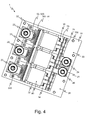
- Fig. 4 shows a plan view of the first power electronic system without housing.
- Fig. 5 shows a three-dimensional representation of a second inventive power electronic system without housing.
- Fig. 1 shows a three-dimensional representation of a first inventive power electronic system 1 in the embodiment of a three-phase inverter.
- a cooling device 10 exemplified as a water cooling device.
- Internal components of the system are covered by a housing 20 towards this cooling device 10 out.
- the housing 10 itself is penetrated at corresponding recesses 220, 240, 260 by the external connection elements 22, 24, 26.
- the two external DC load connection elements 24, 26 are arranged, which are designed as screw connections.
- the external AC load connection elements 22 are shown in basically the same technical expression.
- auxiliary connection elements 28 which serve in particular for the connection of control and sensor signals.
- Fig. 2 and 3 show in three-dimensional view and partially in exploded view the first power electronic system 1 without associated housing with partially different configurations of individual details. Shown in turn is a cooling device 10, here with a plurality of recesses 160, in each case for the arrangement of individual cooling components 60 of respectively associated subsystems 30, 31. There are provided two first 30 and one second subsystem 31, each of these subsystems 30, 31 a power electronic circuit in half-bridge topology includes whereby the power electronic system 1 forms a three-phase bridge circuit.
- Each of the first two subsystems 30 has a cooling component 60 with a substrate 510 bonded thereto in a materially bonded and thermally conductive manner.
- the power electronic circuit is provided, which forms the switching device 50 of the subsystem 30 with the substrate 510 and the cooling member 60.
- From the power electronic circuit internal connection elements 52, 54, 56, 58 go out. Shown here are the two DC voltage load connection elements 54, 56, an AC load connection element 56 and a plurality of control connection elements 58.
- These control connection elements 58 are designed here as terminal lugs, as an alternative to this, spring contact elements or contact pins are also suitable.
- the internal load connection elements 52, 54, 56 are each formed as flat tabs.
- the internal AC load terminal 52 has an electrically isolated current sensor 520 disposed thereon.
- this internal alternating voltage load connection element 52 is connected to the external AC load connection element 22 by force or preferably by material engagement, for example by means of a welded connection.
- the external one AC load terminal 22 protrudes as in Fig. 1 represented by the housing, not shown here.
- the external AC load connection element 22 on an insulating body 32 Arranged is the external AC load connection element 22 on an insulating body 32, which is also part of the first subsystem 30.
- This Isolierstoffmaschine 32 further encloses the frame-like switching device 50 and has fastening means 300 in order to fix the subsystem 30 and thus also the switching device 50 to the cooling device 10.
- the cooling device 10 each have an exception 160, in the form of a recess, in which the associated cooling member 60 of the switching device 50 comes to rest completely.
- the insulating body 32 can rest flat on the cooling member 10 and thus fix the switching device 50 mechanically robust to the cooling device 10.
- the entire switching device 50 is in this case only partially from the insulating material in that upper region, which protrudes from the cooling device 10 comprises.
- This circuit board is provided here in the immediate vicinity of the internal AC load connection element 52, on the one hand to allow short connection paths with the internal auxiliary connection elements 58 of the switching device 50, as well as with the arranged on the internal AC load connection element 52 current sensor 520.
- the circuit board 38 is standing here, ie at an angle between 60 ° and 90 ° to the switching device 50, is provided.
- Fig. 3 shows a basically the same arrangement of the circuit board 38, however, a common circuit board 38 is provided here for all three phases, whereby a simplified embodiment of the control circuit is possible because some electronic components must be provided only once.
- a capacitor device 80 per subsystem 30, 31, which is connected to their fixation, so their mechanical attachment, with the insulating body 32, 33 and here even partially enclosed by this or framed.
- the connection elements of the capacitor 80 are connected in the correct polarity to the internal DC voltage load connection elements 54, 56 of the associated switching device 50.
- the power electronic system 1 has two external DC load connection elements 24, 26, one with positive polarity and one with negative polarity, which are both part of a second subsystem 31, between the first two subsystems 30 and the cooling device 10 is arranged.
- the external DC load connection elements 24, 26 of the second subsystem 31 are electrically conductively connected to two connection devices 74, 76.
- These connecting devices 74, 76 are here designed as flat metallic molded bodies, each having a first contact section for connection to the external DC load connection elements and a second planar section for connection electrically conductive connection with the internal DC load connection elements 54, 56 of the first 30 and of the second subsystem 31.
- Each of the insulating body 32, 33 in this case has a rectangular basic shape, which also forms the basic shape of each subsystem 30, 31.
- the internal 52, 54, 56 and external load connection elements 22, 24, 26 are in this case assigned to the narrow sides of this basic form that the Isolierstoff stresses 32, 33 and thus the subsystems 30, 31 are juxtaposed to each other about their longitudinal sides to the power electronic system 1 is particularly compact embody.
- Fig. 4 shows a plan view of the first power electronic system 1 analogous to that according to Fig. 3 also without housing.
- the basic analogy of the first 30 and second subsystems 31 can be seen, which differ only by the presence of external DC load connection elements 24, 26 and the associated attachment to the Isolierstoff emotions 33.
- the fastening devices 300 for fixing the subsystems 30, 31 to the cooling device 10.
- the modular structure is particularly obvious here, which basically allows any sequence of first 30 and second subsystems 31.
- Fig. 5 shows a three-dimensional representation of a second inventive power electronic system 1 again without housing.
- This power electronic system 1 has two three-phase inverters which have a common DC voltage supply by means of associated external DC load connection elements 24, 26.
- Such power electronic systems 1 are used by way of example in electrically driven industrial trucks, wherein an inverter for the driving functions and a second are provided for the lifting functions for loads.
- the power electronic system 1 here consists of five first 30 and a second subsystem 31, wherein three first subsystems 30 form one of the two inverters and two first 30 and a second subsystem 31 form the other inverter.
- the first subsystems 31 in turn have a switching device 50, which is thermally conductively connected to the cooling device 10. Furthermore, they have internal DC voltage and AC load connection elements, which are both provided on a narrow side of the switching device 50.
- the respective internal AC load terminal elements are connected to associated external AC load terminal elements 22, the screw terminals are formed such that they penetrate the housing, not shown.
- each external AC load connection element 22 is assigned a current sensor 520 here.
- the single second subsystem 31 additionally has orthogonal to the external AC load terminal element 22, the two external DC load connection elements 24, 26, which serve to supply the entire power electronic system.
- these external DC load connection elements 24, 26 are connected by means of two connection devices 74, 76 with all internal DC voltage load connection elements of all switching devices of the first 30 and the second subsystem 31.
- Each of the two inverters has a control circuit assigned to its subsystems 30, 31 forming it.
- These control circuits each have a circuit board 38, which is arranged on the second narrow side of the subsystem 30, 31 and which is provided at an angle of approximately 90 degrees to the orientation of the circuit boards 38 of the subsystems 30, 31. Since above, on the side facing away from the cooling device of the switching devices 50 may be provided at least one associated capacitor device, this arrangement of the circuit boards 38 results in a particularly compact design of the entire power electronic system.
Landscapes
- Physics & Mathematics (AREA)
- Thermal Sciences (AREA)
- Engineering & Computer Science (AREA)
- Microelectronics & Electronic Packaging (AREA)
- Inverter Devices (AREA)
- Power Conversion In General (AREA)
- Dc-Dc Converters (AREA)
Description
- Die Erfindung beschreibt ein integriertes leistungselektronisches System, vorzugsweise zur Ausbildung einer damit realisierten Schaltungsanordnung in Form eines Stromrichters, beispielhaft eines Drei-Phasen-Wechselrichters. Derartige Systeme finden bevorzugt Anwendung in elektrischen Antrieben verschiedener Arten von Fahrzeugen, speziell auch bei Nutzfahrzeugen.
- Es ist grundsätzlich bekannt derartige leistungselektronische System aus einzelnen Leistungshalbleitermodulen beispielhaft gemäß der
DE 10 2009 037 257 A1 mit externer Verschienung, also der Verbindung der externen Anschlusselemente der Leistungshalbleitermodule miteinander aufzubauen. Derartige Systeme weisen den Vorteil auf durch Skalierung beliebig an die notwendige Leistung angepasst werden zu können. Einher geht damit allerdings auch der Nachteil, dass diese System aus einer Mehrzahl von einzelnen Komponenten bestehen und somit keine kompakte Einheit ausbilden. - Es ist ebenso bekannt derartige leistungselektronische Systeme als integrierte Systeme, beispielhaft gemäß der
DE 101 27 947A1 auszugestalten. Bei einem derartigen als Drei-Phasen-Wechselrichter aufgebauten Systemen sind den drei Phasen jeweils eigene Schalteinrichtungen zugeordnet, die mit einer gemeinsamen internen Gleichspannungsverbindung miteinander und mit externen Gleichspannungs-Lastanschlusselementen verbunden sind. Es ist bekannt diese Gleichspannungsverbindung unmittelbar mit einer gemeinsamen Kondensatoreinrichtung für alle Schalteinrichtungen zu verbinden. Derartige Systeme weisen den Vorteil einer kompakten Ausgestaltung bei gleichzeitig hervorragenden elektrischen Eigenschaften auf. Sie bergen allerdings den Nachteil, dass sie durch die Integration vieler Komponenten einer Skalierung und damit einer Anpassung an unterschiedliche Leistungen nicht einfach zugänglich sind. - Aus der
EP 2 261 973 A2 ist weiterhin ein leistungselektronische System mit einer Umhausung, einer Kühleinrichtung, einer Stromrichterschaltung, einem Kondensator sowie ersten und zweiten internen und externen Verbindungseinrichtungenbekannt. Hierbei weist die Stromrichterschaltung ein Substrat mit einer Mehrzahl hierauf angeordneter und mittels der ersten internen Verbindungseinrichtung schaltungsgerecht verbundener Leistungshalbleiterbauelemente auf. Die erste interne Verbindungseinrichtung ist mit zugeordneten Anschlusselementen der Kondensatoren und zweiten internen Verbindungseinrichtungen verbunden. Die Umhausung umschließt zusammen mit der Kühleinrichtung die Stromrichterschaltung, die Kondensatoren und die internen Verbindungseinrichtungen, wobei der hierbei entstandene Innenraum mittels eines Isolierstoffes gefüllt ist. Weiterhin sind die Öffnungen an denen die ersten und zweiten Verbindungseinrichtungen die Umhausung oder die Kühleinrichtung durchdringen gegen Umwelteinflüsse abgedichtet. - Der Erfindung liegt die Aufgabe zugrunde ein leistungselektronisches System vorzustellen, das eine kompakte Einheit bildet und gleichzeitig einer einfachen Skalierung, also einer Anpassung an unterschiedliche Leistungen und auch der Ausbildung verschiedener Schaltungsanordnungen zugänglich ist.
- Die Aufgabe wird erfindungsgemäß gelöst, durch ein leistungselektronisches System mit den Merkmalen des Anspruchs 1. Bevorzugte Ausführungsformen sind in den jeweiligen abhängigen Ansprüchen beschrieben.
- Das vorgestellte leistungselektronische System weist eine Kühleinrichtung, mindestens ein erstes und mindestens ein zweites Subsystem, die mittels mindestens einer internen Verbindungseinrichtung miteinander schaltungsgerecht verbunden sind sowie ein die Subsysteme zur Kühleinrichtung hin überdeckendes Gehäuse auf. Vorzugsweise sind alle Subsysteme in einer Reihe nebeneinander angeordnet.
- Das mindestens eine erste Subsystem weist eine Schalteinrichtung mit einem Kühlbauteil, einen Isolierstoffkörper und ein externes Wechselspannungs-Lastanschlusselement auf. Die Schalteinrichtung wird vorzugsweise aus einem elektrisch isolierenden Substrat mit auf dessen erster Hauptfläche angeordneten und schaltungsgerecht verbundenen Leistungshalbleiterbauelementen, die die leistungselektronischen Schaltung ausbilden, gebildet. Die Schalteinrichtung weist weiterhin interne Lastanschlusselemente verschiedener Polarität auf, von denen mindestens eines mit dem externen Wechselspannungs-Lastanschlusselement ein- oder mehrstückig verbunden ist.
- Das Kühlbauteil ist hierbei mit der zweiten Hauptfläche des Substrats verbunden und hierüber in thermischem Kontakt mit den Leistungshalbleiterbauelementen zur Abführung der dort anfallenden Abwärme. Das Kühlbauteil selbst ist mit der Kühleinrichtung thermisch leitend verbundenen. Der Isolierstoffkörper umfasst hierzu die zugeordnete Schalteinrichtung, die als Halbbrückenschaltungen ausgebildet sein kann, und fixiert das gesamte Subsystem mittels Befestigungselementen zur Kühleinrichtung.
- Das mindestens eine zweite Subsystem ist grundsätzlich analog dem ersten Subsystem aufgebaut, weist allerdings zusätzlich mindestens ein externes Gleichspannungs-Lastanschlusselement, vorzugsweise allerdings zwei, auf, das jeweils geeignet mit dem polaritätsgleichen internen Lastanschlusselement verbunden ist.
- Zudem kann es vorteilhaft sein, wenn jedes erste und zweite Subsystem eine eigene Kondensatoreinrichtung aufweist, die mit dem jeweiligen Isolierstoffkörper zu ihrer Fixierung verbunden ist. Hierbei sind dann die Kontakteinrichtungen der Kondensatoreinrichtung mit den internen Lastanschlusselementen der Schalteinrichtung polaritätsrichtig elektrisch leitend verbunden.
- Ebenso ist es bevorzugt, wenn das mindestens eine erste und das mindestens eine zweite Subsystem eine eigene Steuerschaltung mit einer eigenen zugehörigen Schaltplatine aufweist. Diese Schaltplatine kann mit dem jeweiligen Isolierstoffkörper zu ihrer Fixierung mechanisch verbunden sein. Ebenso kann diese Schaltplatine mit Hilfsanschlusselementen der Schalteinrichtung elektrisch leitend verbunden sein.
- Alternativ kann es bevorzugt sein für eine Mehrzahl von Subsystem, unabhängig davon ob es sich um erste oder zweite Subsystemen handelt, eine gemeinsame Steuerschaltung mit einer zugehörigen Schaltplatine vorzusehen. Auch diese Schaltplatine kann dann mit den jeweiligen Isolierstoffkörpern der Subsysteme zu ihrer Fixierung mechanisch verbunden sein. Ebenso kann diese Schaltplatine mit Hilfsanschlusselementen der zugeordneten Schalteinrichtungen elektrisch leitend verbunden ist.
- Um ein kompakte Ausgestaltung zu realisieren kann jegliche Schaltplatine mit der zugeordneten einzelnen Schalteinrichtung oder mit allen Schalteinrichtungen von nebeneinander angeordneten Subsystemen einen Winkel zwischen 60° und 90° einzuschließen.
- Es kann weiterhin vorteilhaft sein die Schaltplatine in unmittelbarer Nähe des einen externes Wechselspannungs-Lastanschlusselements des zugeordneten Subsystems oder in mittelbarer Nähe der externen Wechselspannungs-Lastanschlusselemente der zugeordneten Subsysteme angeordnet ist. Dies ist insbesondere dann vorteilhaft, wenn die Schaltplatine mit mindestens einem auf einem externen Wechselspannungs-Lastanschlusselement vorgesehenen Stromsensor verbunden ist.
- Die mindestens eine Verbindungseinrichtung verbindet polaritätsrichtig und elektrisch leitend interne Lastanschlusselemente des mindestens einen ersten Subsystems und bevorzugt auch des mindestens einen zweiten Subsystems mit externen Gleichspannungs-Lastanschlusselementen, vorgesehen als Teil mindestens eines zweiten Subsystems.
- Die erfinderische Lösung wird an Hand der Ausführungsbeispiele gemäß den
Fig. 1 bis 5 weiter erläutert. -
Fig. 1 zeigt in dreidimensionaler Darstellung ein erstes erfindungsgemäßes leistungselektronisches System mit seinem Gehäuse. -
Fig. 2 und3 zeigen in dreidimensionaler Darstellung und teilweise in Explosionsdarstellung das erste leistungselektronische System ohne Gehäuse. -
Fig. 4 zeigt eine Draufsicht auf das erste leistungselektronische System ohne Gehäuse. -
Fig. 5 zeigt in dreidimensionaler Darstellung ein zweites erfindungsgemäßes leistungselektronisches System ohne Gehäuse. -
Fig. 1 zeigt in dreidimensionaler Darstellung ein erstes erfindungsgemäßes leistungselektronisches System 1 in Ausgestaltung eines Drei-Phasen-Wechselrichters. Schematisch dargestellt ist eine Kühleinrichtung 10, beispielhaft ausgebildet als eine Wasserkühleinrichtung. Interne Komponenten des Systems werden durch ein Gehäuse 20 zu dieser Kühleinrichtung 10 hin überdeckt. Das Gehäuse 10 selbst wird an entsprechenden Ausnehmungen 220, 240, 260 durch die externen Anschlusselemente 22, 24, 26 durchdrungen. - An einer ersten Seite des Gehäuses 10 sind die beiden externen Gleichspannungs-Lastanschlusselemente 24, 26 angeordnet, die als Schraubverbindungen ausgebildet sind. Auf der gegenüberliegenden zweiten Seite des Gehäuses 10 sind die externen Wechselspannungs-Lastanschlusselemente 22 in grundsätzlich gleicher technischer Ausprägung dargestellt.
- An der Oberseite sind in zwei Gruppen externer Hilfsanschlusselemente 28 vorgesehen, die insbesondere zum Anschluss von Steuer- und Sensorsignalen dienen.
-
Fig. 2 und3 zeigen in dreidimensionaler Darstellung und teilweise in Explosionsdarstellung das erste leistungselektronische System 1 ohne zugeordnetes Gehäuse mit teilweise unterschiedlichen Ausgestaltungen einzelner Details. Dargestellt ist wiederum eine Kühleinrichtung 10, hier mit einer Mehrzahl von Ausnehmungen 160, jeweils zur Anordnung von einzelnen Kühlbauteilen 60 von jeweils zugehörigen Subsystemen 30, 31. Es sind jeweils zwei erste 30 und ein zweites Subsystem 31 vorgesehen, wobei jedes dieser Subsysteme 30, 31 eine leistungselektronische Schaltung in Halbbrückentopologie beinhaltet wodurch das leistungselektronische System 1 eine Drei-Phasen-Brückenschaltung ausbildet. - Die beiden ersten Subsysteme 30 weisen jeweils ein Kühlbauteil 60 mit einem hierauf stoffschlüssig und thermische leitend verbundenen Substrat 510 auf. Auf der dem Kühlbauteil 60 gegenüberliegenden Seite des Substrats 510 ist die leistungselektronische Schaltung vorgesehen, die mit dem Substrat 510 und dem Kühlbauteil 60 die Schalteinrichtung 50 des Subsystems 30 bildet. Von der leistungselektronischen Schaltung gehen interne Anschlusselemente 52, 54, 56, 58 aus. Hier dargestellt sind die jeweils zwei Gleichspannungs-Lastanschlusselemente 54, 56, ein Wechselspannungslastanschlusselement 56 und eine Mehrzahl von Steueranschlusselementen 58. Diese Steueranschlusselemente 58 sind hier als Anschlusslaschen ausgebildet, wobei als Alternative hierzu, beispielhaft Federkontaktelemente oder Kontaktstifte, ebenfalls geeignet sind.
- Die internen Lastanschlusselemente 52, 54, 56 sind jeweils als flächige Laschen ausgebildet. Das interne Wechselspannungs-Lastanschlusselement 52 weist einen hierauf angeordneten elektrisch isolierten Stromsensor 520 auf. In seinem Verlauf ist dieses interne Wechselspannungs-Lastanschlusselement 52 mit dem externen Wechselspannungs-Lastanschlusselement 22 kraft- oder vorzugsweise stoffschlüssig, beispielhaft ausgebildet mittels einer Schweißverbindung, verbunden. Das externe Wechselspannungs-Lastanschlusselement 22 ragt wie in
Fig. 1 dargestellt durch das hier nicht dargestellte Gehäuse hindurch. - Angeordnet ist das externe Wechselspannungs-Lastanschlusselement 22 auf einem Isolierstoffkörper 32, der ebenfalls Teil des ersten Subsystems 30 ist. Dieser Isolierstoffkörper 32 umschließt weiterhin rahmenartig die Schalteinrichtung 50 und weist Befestigungseinrichtungen 300 auf, um das Subsystem 30 und damit auch die Schalteinrichtung 50 zur Kühleinrichtung 10 zu fixieren. In der dargestellten Ausgestaltung weist die Kühleinrichtung 10 jeweils eine Ausnahme 160, in Form einer Vertiefung, auf in der das zugeordnete Kühlbauteil 60 der Schalteinrichtung 50 vollständig zu liegen kommt. Somit kann der Isolierstoffkörper 32 flächig auf dem Kühlbauteil 10 aufliegen und somit die Schalteinrichtung 50 mechanisch robust zur Kühleinrichtung 10 fixieren. Somit wird die gesamte Schalteinrichtung 50 hierbei nur teilweise vom Isolierstoffkörper in demjenigen oberen Bereich, der aus der Kühleinrichtung 10 herausragt umfasst.
- Weiterhin weist in Ausgestaltung gemäß
Fig. 2 jeder Isolierstoffkörper 32 eine Halteeinrichtung 328 zur Fixierung einer zugeordneten nicht dargestellten Schaltplatine, die die Steuerschaltung für das Subsystem 30 beinhaltet, auf. Diese Schaltplatine ist hier in unmittelbarer Nähe zum internen Wechselspannungs-Lastanschlusselement 52 vorgesehen, um einerseits kurze Verbindungswege mit den internen Hilfsanschlusselementen 58 der Schalteinrichtung 50, wie auch mit dem auf dem internen Wechselspannungs-Lastanschlusselement 52 angeordneten Stromsensor 520 zu erlauben. Zur kompakten Ausgestaltung des gesamten leistungselektronischen Systems 1 ist die Schaltplatine 38 hier stehend, also unter einem Winkel zwischen 60° und 90° zur Schalteinrichtung 50, vorgesehen. - Die Ausgestaltung gemäß
Fig. 3 zeigt eine grundsätzlich gleiche Anordnung der Schaltplatine 38, allerdings ist hier für alle drei Phasen eine gemeinsame Schaltplatine 38 vorgesehen, wodurch eine vereinfachte Ausgestaltung der Steuerschaltung möglich ist, da manche elektronische Komponenten nur einmal vorgesehen werden müssen. - Ebenso in
Fig. 3 , nicht aber inFig. 2 , dargestellt ist eine Kondensatoreinrichtung 80 je Subsystem 30, 31, die zu ihrer Fixierung, also ihrer mechanischen Befestigung, mit dem Isolierstoffkörper 32, 33 verbunden und hier sogar teilweise von diesem umschlossen bzw. umrahmt ist. Die Anschlusselemente des Kondensators 80 sind polaritätsrichtig mit den internen Gleichspannungs-Lastanschlusselementen 54, 56 der zugeordneten Schalteinrichtung 50 verbunden. - Zur Gleichspannungsversorgung weist das leistungselektronische System 1 zwei externe Gleichspannungs-Lastanschlusselemente 24, 26, eines mit positiver und eines mit negativer Polarität, auf, die beide Teil eines zweiten Subsystems 31 sind, das zwischen den beiden ersten Subsystemen 30 auf bzw. zu der Kühleinrichtung 10 angeordnet ist. Die externen Gleichspannungs-Lastanschlusselemente 24, 26 des zweiten Subsystems 31 sind mit zwei Verbindungseinrichtungen 74, 76 elektrisch leitend verbunden. Diese Verbindungseinrichtungen 74, 76 sind hier als flächige metallische Formkörper ausgebildet, jeweils mit einem ersten Kontaktabschnitt zur Verbindung mit den externen Gleichspannungs-Lastanschlusselementen und mit einem zweiten flächigen Abschnitt zur Verbindung elektrisch leitenden Verbindung mit den internen Gleichspannungs-Lastanschlusselementen 54, 56 der ersten 30 und des zweiten Subsystems 31.
- Jeder der Isolierstoffkörper 32, 33 weist hierbei eine rechteckige Grundform auf, die auch die Grundform jedes Subsystems 30, 31 bildet. Die internen 52, 54, 56 und externen Lastanschlusselemente 22, 24, 26 sind hierbei derart den Schmalseiten dieser Grundform zugeordnet, dass die Isolierstoffkörper 32, 33 und damit die Subsysteme 30, 31 über ihre Längsseiten aneinander anreihbar sind um das leistungselektronische System 1 besonders kompakt auszugestalten.
-
Fig. 4 zeigt eine Draufsicht auf das erste leistungselektronische System 1 analog demjenigen gemäßFig. 3 ebenfalls ohne Gehäuse. Besonders deutlich ist hier die grundsätzliche Analogie der ersten 30 und zweiten Subsysteme 31 erkennbar, die sich nur durch das Vorhandensein von externen Gleichspannungs-Lastanschlusselementen 24, 26 und der zugehörigen Befestigung auf dem Isolierstoffkörper 33 unterscheiden. Ebenso erkennbar sind die Befestigungseinrichtungen 300 zur Fixierung der Subsysteme 30, 31 zur Kühleinrichtung 10. Ebenso wird hier der modulare Aufbau besonders offensichtlich, der grundsätzlich eine beliebige Aneinanderreihung von ersten 30 und zweiten Subsystemen 31 ermöglicht. -
Fig. 5 zeigt in dreidimensionaler Darstellung ein zweites erfindungsgemäßes leistungselektronisches System 1 wiederum ohne Gehäuse. Dieses leistungselektronische System 1 weist zwei Drei-Phasen-Wechselrichter auf, die eine gemeinsame Gleichspannungsversorgung mittels zugeordneter externen Gleichspannungs-Lastanschlusselemente 24, 26 aufweisen. Derartige leistungselektronische Systeme 1 werden beispielhaft in elektrisch angetriebenen Flurförderzeugen verwendet, wobei ein Wechselrichter für die Fahrfunktionen und ein zweiter für die Hebefunktionen für Lasten vorgesehen sind. Das leistungselektronische System 1 besteht hierbei aus fünf ersten 30 und einem zweiten Subsystem 31, wobei drei erste Subsysteme 30 einen der beiden Wechselrichter ausbilden und zwei erste 30 und ein zweites Subsystem 31 den anderen Wechselrichter ausbilden. - Die ersten Subsysteme 31 weisen wiederum eine Schalteinrichtung 50 auf, die mit der Kühleinrichtung 10 thermisch leitend verbunden ist. Weiterhin weisen sie interne Gleichspannungs- und Wechselspannungs-Lastanschlusselemente auf, die beide auf einer Schmalseite der Schalteinrichtung 50 vorgesehen sind. Die jeweiligen internen Wechselspannungs-Lastanschlusselemente sind mit zugeordneten externen Wechselspannungs-Lastanschlusselementen 22 verbunden, deren Schraubanschlüsse derart ausgebildet sind, dass sie das nicht dargestellte Gehäuse durchdringen. Zudem ist hier jedem externen Wechselspannungs-Lastanschlusselement 22 ein Stromsensor 520 zugeordnet.
- Das einzige zweite Subsystem 31 weist zusätzlich orthogonal zu dem externen Wechselspannungs-Lastanschlusselement 22 angeordnet die beiden externe Gleichspannungs-Lastanschlusselemente 24, 26 auf, die der Versorgung des gesamten leistungselektronischen Systems dienen. Hierzu sind diese externen Gleichspannungs-Lastanschlusselemente 24, 26 mittels zweier Verbindungseinrichtungen 74, 76 mit allen internen Gleichspannungs-Lastanschlusselementen aller Schalteinrichtungen der ersten 30 und des zweiten Subsystems 31 verbunden.
- Jeder der beiden Wechselrichter weist seinen ihn bildenden Subsystemen 30, 31 zugeordnet eine Steuerschaltung auf. Diese Steuerschaltungen weisen jeweils eine Schaltplatine 38 auf, die auf der zweiten Schmalseite der Subsystem 30, 31 angeordnet ist und die in einem Winkel von circa 90 Grad zu der Orientierung der Schaltplatinen 38 der Subsysteme 30, 31 vorgesehen ist. Da oberhalb, auf der der Kühleinrichtung abgewandten Seite der Schalteinrichtungen 50 mindestens eine zugeordnete Kondensatoreinrichtung vorgesehen sein kann ergibt diese Anordnung der Schaltplatinen 38 eine besonders kompakte Ausgestaltung des gesamten leistungselektronischen Systems 1.
Claims (7)
- Leistungselektronisches System (1) mit einer Kühleinrichtung (10), mindestens einem ersten (30) und mindestens einem zweiten Subsystem (31), mindestens einer Verbindungseinrichtung (74, 76) und einem Gehäuse (20), wobei
das mindestens eine erste Subsystem (30) eine Schalteinrichtung (50) mit einem mit der Kühleinrichtung (10) thermisch leitend verbundenen Kühlbauteil (60) und einer hierauf angeordneten leistungselektronischen Schaltung mit ersten internen Lastanschlusselementen (52, 54, 56) verschiedener Polarität, einen Isolierstoffkörper (32) und ein externes Wechselspannungs-Lastanschlusselement (22) aufweist,
das mindestens eine zweite Subsystem (31) analog dem ersten Subsystem (30) aufgebaut ist und zusätzlich mindestens ein externes Gleichspannungs-Lastanschlusselement (24, 26) aufweist,
wobei die mindestens eine Verbindungseinrichtung (74, 76) interne Gleichspannungs-Lastanschlusselemente (54, 56) der ersten (30) und zweiten Subsysteme (31) mit externen Gleichspannungs-Lastanschlusselementen (24, 26) des mindestens einen zweiten Subsystems (31) polaritätsrichtig elektrisch leitend verbindet und wobei das Gehäuse (20) alle Subsysteme (30, 31) zur Kühleinrichtung (10) hin überdeckt und wobei
der Isolierstoffkörper (32, 33) die zugeordnete Schalteinrichtung (50) zumindest teilweise umfasst und das jeweilige erste (30) oder zweite Subsystem (31) mittels Befestigungselementen (300) zur Kühleinrichtung (10) fixiert. - Leistungselektronisches System nach Anspruch 1, wobei
jedes erste (30) und zweite Subsystem (31) eine Kondensatoreinrichtung (80) aufweist, die mit dem jeweiligen Isolierstoffkörper (32, 33) zu ihrer Fixierung verbunden ist und die mit den ersten internen Gleichspannungs-Lastanschlusselementen (54, 56) der Schalteinrichtung (50) polaritätsrichtig elektrisch leitend verbunden ist. - Leistungselektronisches System nach Anspruch 1, wobei
jedes erste (30) und zweite Subsystem (31) eine Steuerschaltung mit einer zugehörigen Schaltplatine (38) aufweist, die mit dem jeweiligen Isolierstoffkörper (32, 33) zu ihrer Fixierung verbunden ist und die mit Hilfsanschlusselementen (58) der Schalteinrichtung (50) elektrisch leitend verbunden ist. - Leistungselektronisches System nach Anspruch 1, wobei
für eine Mehrzahl von Subsystemen (30, 31) eine gemeinsam Steuerschaltung mit einer zugehörigen Schaltplatine (38) vorgesehen ist, die mit den jeweiligen Isolierstoffkörpern (32, 33) der Subsysteme (30, 31) zu ihrer Fixierung verbunden ist und die mit Hilfsanschlusselementen (58) der zugeordneten Schalteinrichtungen (50) elektrisch leitend verbunden ist. - Leistungselektronisches System nach Anspruch 4, wobei
die Schaltplatine (38) mit der Schalteinrichtung (50) einen Winkel zwischen 60° und 90° einschließt. - Leistungselektronisches System nach Anspruch 4 oder 5, wobei
die Schaltplatine (38) in unmittelbarer Nähe mindestens eines externen Wechselspannungs-Lastanschlusselements (22) angeordnet ist und mit mindestens einem auf diesem externen Wechselspannungs-Lastanschlusselement (22) oder auf dem zugeordneten internen Wechselspannungs-Lastanschlusselement (52) vorgesehenen Stromsensor (520) verbunden ist. - Leistungselektronisches System nach Anspruch 1, wobei
die jeweiligen leistungselektronischen Schaltungen (40) als Halbbrückenschaltungen ausgebildet sind.
Applications Claiming Priority (1)
| Application Number | Priority Date | Filing Date | Title |
|---|---|---|---|
| DE102011076323.6A DE102011076323B4 (de) | 2011-05-24 | 2011-05-24 | Leistungselektronisches System mit erstem und zweitem Subsystem |
Publications (2)
| Publication Number | Publication Date |
|---|---|
| EP2528095A1 EP2528095A1 (de) | 2012-11-28 |
| EP2528095B1 true EP2528095B1 (de) | 2013-12-25 |
Family
ID=45932198
Family Applications (1)
| Application Number | Title | Priority Date | Filing Date |
|---|---|---|---|
| EP12161485.3A Not-in-force EP2528095B1 (de) | 2011-05-24 | 2012-03-27 | Leistungselektronisches System mit erstem und zweitem Subsystem |
Country Status (4)
| Country | Link |
|---|---|
| EP (1) | EP2528095B1 (de) |
| KR (1) | KR101872035B1 (de) |
| CN (2) | CN202940231U (de) |
| DE (1) | DE102011076323B4 (de) |
Families Citing this family (6)
| Publication number | Priority date | Publication date | Assignee | Title |
|---|---|---|---|---|
| DE102011076323B4 (de) * | 2011-05-24 | 2014-04-10 | Semikron Elektronik Gmbh & Co. Kg | Leistungselektronisches System mit erstem und zweitem Subsystem |
| DE102013103116B3 (de) * | 2013-03-27 | 2014-09-18 | Semikron Elektronik Gmbh & Co. Kg | Leistungshalbleitermodul und Verfahren zur Herstellung eines Leistungshalbleitermoduls |
| DE102013110818A1 (de) | 2013-09-30 | 2015-04-02 | Semikron Elektronik Gmbh & Co. Kg | Leistungshalbleitereinrichtung |
| DE102014109816B4 (de) | 2014-07-14 | 2016-11-03 | Infineon Technologies Ag | Leistungshalbleitermodul und System mit mindestens zwei Leistungshalbleitermodulen |
| DE102017129707B4 (de) * | 2017-12-13 | 2024-12-12 | Semikron Elektronik Gmbh & Co. Kg | Verfahren zur Herstellung eines leistungselektronischen Systems |
| DE102019218206B4 (de) | 2019-11-25 | 2023-08-24 | Lenze Swiss Ag | Frequenzumrichter-Baureihe |
Family Cites Families (8)
| Publication number | Priority date | Publication date | Assignee | Title |
|---|---|---|---|---|
| EP1028520A4 (de) * | 1996-09-06 | 2000-08-16 | Hitachi Ltd | Halbleiteranordnung |
| DE10127947C1 (de) * | 2001-08-22 | 2002-10-17 | Semikron Elektronik Gmbh | Schaltungsanordnung |
| JP2006186170A (ja) * | 2004-12-28 | 2006-07-13 | Nissan Motor Co Ltd | 半導体装置 |
| DE102008018841A1 (de) * | 2008-04-15 | 2009-10-22 | Conti Temic Microelectronic Gmbh | Verfahren zur Herstellung und Aufbau eines Leistungsmoduls |
| JP4607995B2 (ja) * | 2008-11-28 | 2011-01-05 | 三菱電機株式会社 | 電力用半導体装置 |
| DE102009024369B4 (de) * | 2009-06-09 | 2011-12-29 | Semikron Elektronik Gmbh & Co. Kg | Leistungselektronisches System |
| DE102009037257B4 (de) | 2009-08-12 | 2014-07-31 | Semikron Elektronik Gmbh & Co. Kg | Leistungshalbleitermodul mit Schaltungsträger und Lastanschlusselement sowie Herstellungsverfahren hierzu |
| DE102011076323B4 (de) * | 2011-05-24 | 2014-04-10 | Semikron Elektronik Gmbh & Co. Kg | Leistungselektronisches System mit erstem und zweitem Subsystem |
-
2011
- 2011-05-24 DE DE102011076323.6A patent/DE102011076323B4/de not_active Expired - Fee Related
-
2012
- 2012-03-27 EP EP12161485.3A patent/EP2528095B1/de not_active Not-in-force
- 2012-05-24 CN CN201220238404.0U patent/CN202940231U/zh not_active Withdrawn - After Issue
- 2012-05-24 KR KR1020120055225A patent/KR101872035B1/ko not_active Expired - Fee Related
- 2012-05-24 CN CN201210165096.8A patent/CN102800638B/zh not_active Expired - Fee Related
Also Published As
| Publication number | Publication date |
|---|---|
| EP2528095A1 (de) | 2012-11-28 |
| DE102011076323B4 (de) | 2014-04-10 |
| CN102800638A (zh) | 2012-11-28 |
| DE102011076323A1 (de) | 2012-11-29 |
| KR101872035B1 (ko) | 2018-06-27 |
| CN102800638B (zh) | 2017-04-12 |
| CN202940231U (zh) | 2013-05-15 |
| KR20120131110A (ko) | 2012-12-04 |
Similar Documents
| Publication | Publication Date | Title |
|---|---|---|
| EP2528091B1 (de) | Leistungselektronisches System mit Subsystemen und einer Kühleinrichtung | |
| DE102011076324B4 (de) | Leistungselektronisches System mit Verbindungseinrichtung erster und zweiter Subsysteme | |
| EP2528095B1 (de) | Leistungselektronisches System mit erstem und zweitem Subsystem | |
| DE102017115883B4 (de) | Leistungselektronisches Submodul mit Gleich- und Wechselspannungsanschlusselementen und Anordnung hiermit | |
| EP2654392B1 (de) | Anreihbares flüssigkeitsgekühltes Leistungshalbleitermodul und Anordnung hiermit | |
| DE102013104950B3 (de) | Leistungshalbleitermodul und Anordnung hiermit | |
| DE102011078811B3 (de) | Leistungselektronisches System mit einer Kühleinrichtung | |
| DE102016208273B4 (de) | Leistungsumsetzungsvorrichtung | |
| EP2302782A1 (de) | Stromrichteranordnung | |
| DE102020006207A1 (de) | Motorantriebsvorrichtung mit Glättungskondensatoreinheit und Beschaltungskondensator | |
| DE202015004662U1 (de) | Zwischenkreiskondensatormodul mit niederinduktiven Busbar-Verbindungen | |
| EP0994557B1 (de) | Umrichter mit niederinduktivem Kondensator im Zwischenkreis | |
| EP2814308B1 (de) | 3-Level-Stromrichtereinrichtung | |
| EP1433204A2 (de) | Anordnung mit leistungshalbleiterbauelementen zur leistungssteuerung hoher ströme und anwendung der anordnung | |
| DE10340297A1 (de) | Schaltungsanordnung für aktive und passive elektrische und elektronische Bauelemente | |
| DE102017110722B4 (de) | Leistungselektronische Anordnung und elektrisches Fahrzeug hiermit | |
| DE112019003853T5 (de) | Elektrischer Verteilerkasten | |
| DE2611260C3 (de) | Stromrichterbaueinheit | |
| EP2986092B1 (de) | Schaltschrank | |
| DE102017127895A1 (de) | Wechselrichter für Elektromotor | |
| EP2562922A1 (de) | Modular aufgebaute Stromrichteranordnung | |
| DE102022123261B4 (de) | Leistungselektronische Baugruppe mit einem Gehäuse und mit einer darin angeordneten Kondensatoreinrichtung | |
| DE102013021240A1 (de) | Zellverbinderplatine und Batteriezellenblock mit einer Zellverbinderplatine | |
| DE102019204889A1 (de) | Elektronische Schaltungseinheit | |
| DE102019115498B4 (de) | Leistungselektronisches Submodul mit Gleich- und Wechselpotentialanschlussflächen und Anordnung hiermit |
Legal Events
| Date | Code | Title | Description |
|---|---|---|---|
| PUAI | Public reference made under article 153(3) epc to a published international application that has entered the european phase |
Free format text: ORIGINAL CODE: 0009012 |
|
| AK | Designated contracting states |
Kind code of ref document: A1 Designated state(s): AL AT BE BG CH CY CZ DE DK EE ES FI FR GB GR HR HU IE IS IT LI LT LU LV MC MK MT NL NO PL PT RO RS SE SI SK SM TR |
|
| AX | Request for extension of the european patent |
Extension state: BA ME |
|
| 17P | Request for examination filed |
Effective date: 20130528 |
|
| GRAP | Despatch of communication of intention to grant a patent |
Free format text: ORIGINAL CODE: EPIDOSNIGR1 |
|
| INTG | Intention to grant announced |
Effective date: 20130927 |
|
| GRAS | Grant fee paid |
Free format text: ORIGINAL CODE: EPIDOSNIGR3 |
|
| GRAA | (expected) grant |
Free format text: ORIGINAL CODE: 0009210 |
|
| AK | Designated contracting states |
Kind code of ref document: B1 Designated state(s): AL AT BE BG CH CY CZ DE DK EE ES FI FR GB GR HR HU IE IS IT LI LT LU LV MC MK MT NL NO PL PT RO RS SE SI SK SM TR |
|
| REG | Reference to a national code |
Ref country code: GB Ref legal event code: FG4D Free format text: NOT ENGLISH |
|
| REG | Reference to a national code |
Ref country code: CH Ref legal event code: EP |
|
| REG | Reference to a national code |
Ref country code: AT Ref legal event code: REF Ref document number: 646995 Country of ref document: AT Kind code of ref document: T Effective date: 20140115 |
|
| REG | Reference to a national code |
Ref country code: IE Ref legal event code: FG4D Free format text: LANGUAGE OF EP DOCUMENT: GERMAN |
|
| REG | Reference to a national code |
Ref country code: DE Ref legal event code: R096 Ref document number: 502012000285 Country of ref document: DE Effective date: 20140220 |
|
| PG25 | Lapsed in a contracting state [announced via postgrant information from national office to epo] |
Ref country code: NO Free format text: LAPSE BECAUSE OF FAILURE TO SUBMIT A TRANSLATION OF THE DESCRIPTION OR TO PAY THE FEE WITHIN THE PRESCRIBED TIME-LIMIT Effective date: 20140325 Ref country code: HR Free format text: LAPSE BECAUSE OF FAILURE TO SUBMIT A TRANSLATION OF THE DESCRIPTION OR TO PAY THE FEE WITHIN THE PRESCRIBED TIME-LIMIT Effective date: 20131225 Ref country code: SE Free format text: LAPSE BECAUSE OF FAILURE TO SUBMIT A TRANSLATION OF THE DESCRIPTION OR TO PAY THE FEE WITHIN THE PRESCRIBED TIME-LIMIT Effective date: 20131225 Ref country code: LT Free format text: LAPSE BECAUSE OF FAILURE TO SUBMIT A TRANSLATION OF THE DESCRIPTION OR TO PAY THE FEE WITHIN THE PRESCRIBED TIME-LIMIT Effective date: 20131225 Ref country code: FI Free format text: LAPSE BECAUSE OF FAILURE TO SUBMIT A TRANSLATION OF THE DESCRIPTION OR TO PAY THE FEE WITHIN THE PRESCRIBED TIME-LIMIT Effective date: 20131225 |
|
| REG | Reference to a national code |
Ref country code: NL Ref legal event code: VDEP Effective date: 20131225 |
|
| REG | Reference to a national code |
Ref country code: LT Ref legal event code: MG4D |
|
| PG25 | Lapsed in a contracting state [announced via postgrant information from national office to epo] |
Ref country code: LV Free format text: LAPSE BECAUSE OF FAILURE TO SUBMIT A TRANSLATION OF THE DESCRIPTION OR TO PAY THE FEE WITHIN THE PRESCRIBED TIME-LIMIT Effective date: 20131225 Ref country code: RS Free format text: LAPSE BECAUSE OF FAILURE TO SUBMIT A TRANSLATION OF THE DESCRIPTION OR TO PAY THE FEE WITHIN THE PRESCRIBED TIME-LIMIT Effective date: 20131225 |
|
| PG25 | Lapsed in a contracting state [announced via postgrant information from national office to epo] |
Ref country code: EE Free format text: LAPSE BECAUSE OF FAILURE TO SUBMIT A TRANSLATION OF THE DESCRIPTION OR TO PAY THE FEE WITHIN THE PRESCRIBED TIME-LIMIT Effective date: 20131225 Ref country code: IS Free format text: LAPSE BECAUSE OF FAILURE TO SUBMIT A TRANSLATION OF THE DESCRIPTION OR TO PAY THE FEE WITHIN THE PRESCRIBED TIME-LIMIT Effective date: 20140425 |
|
| PG25 | Lapsed in a contracting state [announced via postgrant information from national office to epo] |
Ref country code: CZ Free format text: LAPSE BECAUSE OF FAILURE TO SUBMIT A TRANSLATION OF THE DESCRIPTION OR TO PAY THE FEE WITHIN THE PRESCRIBED TIME-LIMIT Effective date: 20131225 Ref country code: RO Free format text: LAPSE BECAUSE OF FAILURE TO SUBMIT A TRANSLATION OF THE DESCRIPTION OR TO PAY THE FEE WITHIN THE PRESCRIBED TIME-LIMIT Effective date: 20131225 Ref country code: ES Free format text: LAPSE BECAUSE OF FAILURE TO SUBMIT A TRANSLATION OF THE DESCRIPTION OR TO PAY THE FEE WITHIN THE PRESCRIBED TIME-LIMIT Effective date: 20131225 Ref country code: SK Free format text: LAPSE BECAUSE OF FAILURE TO SUBMIT A TRANSLATION OF THE DESCRIPTION OR TO PAY THE FEE WITHIN THE PRESCRIBED TIME-LIMIT Effective date: 20131225 Ref country code: NL Free format text: LAPSE BECAUSE OF FAILURE TO SUBMIT A TRANSLATION OF THE DESCRIPTION OR TO PAY THE FEE WITHIN THE PRESCRIBED TIME-LIMIT Effective date: 20131225 Ref country code: PT Free format text: LAPSE BECAUSE OF FAILURE TO SUBMIT A TRANSLATION OF THE DESCRIPTION OR TO PAY THE FEE WITHIN THE PRESCRIBED TIME-LIMIT Effective date: 20140428 Ref country code: CY Free format text: LAPSE BECAUSE OF FAILURE TO SUBMIT A TRANSLATION OF THE DESCRIPTION OR TO PAY THE FEE WITHIN THE PRESCRIBED TIME-LIMIT Effective date: 20131225 |
|
| REG | Reference to a national code |
Ref country code: DE Ref legal event code: R097 Ref document number: 502012000285 Country of ref document: DE |
|
| PG25 | Lapsed in a contracting state [announced via postgrant information from national office to epo] |
Ref country code: DK Free format text: LAPSE BECAUSE OF FAILURE TO SUBMIT A TRANSLATION OF THE DESCRIPTION OR TO PAY THE FEE WITHIN THE PRESCRIBED TIME-LIMIT Effective date: 20131225 Ref country code: LU Free format text: LAPSE BECAUSE OF FAILURE TO SUBMIT A TRANSLATION OF THE DESCRIPTION OR TO PAY THE FEE WITHIN THE PRESCRIBED TIME-LIMIT Effective date: 20140327 |
|
| PLBE | No opposition filed within time limit |
Free format text: ORIGINAL CODE: 0009261 |
|
| STAA | Information on the status of an ep patent application or granted ep patent |
Free format text: STATUS: NO OPPOSITION FILED WITHIN TIME LIMIT |
|
| PG25 | Lapsed in a contracting state [announced via postgrant information from national office to epo] |
Ref country code: PL Free format text: LAPSE BECAUSE OF FAILURE TO SUBMIT A TRANSLATION OF THE DESCRIPTION OR TO PAY THE FEE WITHIN THE PRESCRIBED TIME-LIMIT Effective date: 20131225 |
|
| 26N | No opposition filed |
Effective date: 20140926 |
|
| REG | Reference to a national code |
Ref country code: IE Ref legal event code: MM4A |
|
| REG | Reference to a national code |
Ref country code: DE Ref legal event code: R097 Ref document number: 502012000285 Country of ref document: DE Effective date: 20140926 |
|
| PG25 | Lapsed in a contracting state [announced via postgrant information from national office to epo] |
Ref country code: IE Free format text: LAPSE BECAUSE OF NON-PAYMENT OF DUE FEES Effective date: 20140327 |
|
| PG25 | Lapsed in a contracting state [announced via postgrant information from national office to epo] |
Ref country code: SI Free format text: LAPSE BECAUSE OF FAILURE TO SUBMIT A TRANSLATION OF THE DESCRIPTION OR TO PAY THE FEE WITHIN THE PRESCRIBED TIME-LIMIT Effective date: 20131225 |
|
| REG | Reference to a national code |
Ref country code: CH Ref legal event code: PL |
|
| PG25 | Lapsed in a contracting state [announced via postgrant information from national office to epo] |
Ref country code: LI Free format text: LAPSE BECAUSE OF NON-PAYMENT OF DUE FEES Effective date: 20150331 Ref country code: CH Free format text: LAPSE BECAUSE OF NON-PAYMENT OF DUE FEES Effective date: 20150331 |
|
| PG25 | Lapsed in a contracting state [announced via postgrant information from national office to epo] |
Ref country code: MT Free format text: LAPSE BECAUSE OF FAILURE TO SUBMIT A TRANSLATION OF THE DESCRIPTION OR TO PAY THE FEE WITHIN THE PRESCRIBED TIME-LIMIT Effective date: 20131225 |
|
| REG | Reference to a national code |
Ref country code: FR Ref legal event code: PLFP Year of fee payment: 5 |
|
| PG25 | Lapsed in a contracting state [announced via postgrant information from national office to epo] |
Ref country code: SM Free format text: LAPSE BECAUSE OF FAILURE TO SUBMIT A TRANSLATION OF THE DESCRIPTION OR TO PAY THE FEE WITHIN THE PRESCRIBED TIME-LIMIT Effective date: 20131225 |
|
| PG25 | Lapsed in a contracting state [announced via postgrant information from national office to epo] |
Ref country code: MC Free format text: LAPSE BECAUSE OF FAILURE TO SUBMIT A TRANSLATION OF THE DESCRIPTION OR TO PAY THE FEE WITHIN THE PRESCRIBED TIME-LIMIT Effective date: 20131225 |
|
| PG25 | Lapsed in a contracting state [announced via postgrant information from national office to epo] |
Ref country code: GR Free format text: LAPSE BECAUSE OF FAILURE TO SUBMIT A TRANSLATION OF THE DESCRIPTION OR TO PAY THE FEE WITHIN THE PRESCRIBED TIME-LIMIT Effective date: 20140326 Ref country code: BG Free format text: LAPSE BECAUSE OF FAILURE TO SUBMIT A TRANSLATION OF THE DESCRIPTION OR TO PAY THE FEE WITHIN THE PRESCRIBED TIME-LIMIT Effective date: 20131225 |
|
| PG25 | Lapsed in a contracting state [announced via postgrant information from national office to epo] |
Ref country code: BE Free format text: LAPSE BECAUSE OF FAILURE TO SUBMIT A TRANSLATION OF THE DESCRIPTION OR TO PAY THE FEE WITHIN THE PRESCRIBED TIME-LIMIT Effective date: 20140331 Ref country code: TR Free format text: LAPSE BECAUSE OF FAILURE TO SUBMIT A TRANSLATION OF THE DESCRIPTION OR TO PAY THE FEE WITHIN THE PRESCRIBED TIME-LIMIT Effective date: 20131225 Ref country code: HU Free format text: LAPSE BECAUSE OF FAILURE TO SUBMIT A TRANSLATION OF THE DESCRIPTION OR TO PAY THE FEE WITHIN THE PRESCRIBED TIME-LIMIT; INVALID AB INITIO Effective date: 20120327 |
|
| REG | Reference to a national code |
Ref country code: FR Ref legal event code: PLFP Year of fee payment: 6 |
|
| REG | Reference to a national code |
Ref country code: FR Ref legal event code: PLFP Year of fee payment: 7 |
|
| REG | Reference to a national code |
Ref country code: AT Ref legal event code: MM01 Ref document number: 646995 Country of ref document: AT Kind code of ref document: T Effective date: 20170327 |
|
| PG25 | Lapsed in a contracting state [announced via postgrant information from national office to epo] |
Ref country code: MK Free format text: LAPSE BECAUSE OF FAILURE TO SUBMIT A TRANSLATION OF THE DESCRIPTION OR TO PAY THE FEE WITHIN THE PRESCRIBED TIME-LIMIT Effective date: 20131225 |
|
| PG25 | Lapsed in a contracting state [announced via postgrant information from national office to epo] |
Ref country code: AT Free format text: LAPSE BECAUSE OF NON-PAYMENT OF DUE FEES Effective date: 20170327 |
|
| PG25 | Lapsed in a contracting state [announced via postgrant information from national office to epo] |
Ref country code: AL Free format text: LAPSE BECAUSE OF FAILURE TO SUBMIT A TRANSLATION OF THE DESCRIPTION OR TO PAY THE FEE WITHIN THE PRESCRIBED TIME-LIMIT Effective date: 20131225 |
|
| PGFP | Annual fee paid to national office [announced via postgrant information from national office to epo] |
Ref country code: FR Payment date: 20210319 Year of fee payment: 10 |
|
| PGFP | Annual fee paid to national office [announced via postgrant information from national office to epo] |
Ref country code: GB Payment date: 20210324 Year of fee payment: 10 |
|
| PGFP | Annual fee paid to national office [announced via postgrant information from national office to epo] |
Ref country code: DE Payment date: 20210331 Year of fee payment: 10 Ref country code: IT Payment date: 20210331 Year of fee payment: 10 |
|
| REG | Reference to a national code |
Ref country code: DE Ref legal event code: R119 Ref document number: 502012000285 Country of ref document: DE |
|
| GBPC | Gb: european patent ceased through non-payment of renewal fee |
Effective date: 20220327 |
|
| PG25 | Lapsed in a contracting state [announced via postgrant information from national office to epo] |
Ref country code: GB Free format text: LAPSE BECAUSE OF NON-PAYMENT OF DUE FEES Effective date: 20220327 Ref country code: FR Free format text: LAPSE BECAUSE OF NON-PAYMENT OF DUE FEES Effective date: 20220331 Ref country code: DE Free format text: LAPSE BECAUSE OF NON-PAYMENT OF DUE FEES Effective date: 20221001 |
|
| PG25 | Lapsed in a contracting state [announced via postgrant information from national office to epo] |
Ref country code: IT Free format text: LAPSE BECAUSE OF NON-PAYMENT OF DUE FEES Effective date: 20220327 |