EP2528101A2 - Farbstoffsensibilisierte Solarzelle - Google Patents
Farbstoffsensibilisierte Solarzelle Download PDFInfo
- Publication number
- EP2528101A2 EP2528101A2 EP12181001A EP12181001A EP2528101A2 EP 2528101 A2 EP2528101 A2 EP 2528101A2 EP 12181001 A EP12181001 A EP 12181001A EP 12181001 A EP12181001 A EP 12181001A EP 2528101 A2 EP2528101 A2 EP 2528101A2
- Authority
- EP
- European Patent Office
- Prior art keywords
- counter electrode
- working electrode
- conductive material
- filamentous
- conductive substrate
- Prior art date
- Legal status (The legal status is an assumption and is not a legal conclusion. Google has not performed a legal analysis and makes no representation as to the accuracy of the status listed.)
- Withdrawn
Links
- 239000004065 semiconductor Substances 0.000 claims abstract description 39
- 239000000758 substrate Substances 0.000 claims abstract description 33
- 239000003792 electrolyte Substances 0.000 claims abstract description 18
- 230000001235 sensitizing effect Effects 0.000 claims abstract description 8
- 239000002245 particle Substances 0.000 claims abstract description 5
- 239000004020 conductor Substances 0.000 claims description 35
- 239000010410 layer Substances 0.000 claims description 27
- 239000007787 solid Substances 0.000 claims description 8
- 239000002131 composite material Substances 0.000 claims description 5
- 239000012811 non-conductive material Substances 0.000 claims description 5
- 239000003054 catalyst Substances 0.000 claims description 3
- 239000012792 core layer Substances 0.000 claims description 2
- 239000000975 dye Substances 0.000 description 28
- 239000000463 material Substances 0.000 description 12
- GWEVSGVZZGPLCZ-UHFFFAOYSA-N Titan oxide Chemical compound O=[Ti]=O GWEVSGVZZGPLCZ-UHFFFAOYSA-N 0.000 description 10
- 238000000034 method Methods 0.000 description 8
- 239000010935 stainless steel Substances 0.000 description 8
- 229910001220 stainless steel Inorganic materials 0.000 description 8
- 238000010586 diagram Methods 0.000 description 6
- LFQSCWFLJHTTHZ-UHFFFAOYSA-N Ethanol Chemical compound CCO LFQSCWFLJHTTHZ-UHFFFAOYSA-N 0.000 description 4
- 239000011248 coating agent Substances 0.000 description 4
- 238000000576 coating method Methods 0.000 description 4
- 230000000694 effects Effects 0.000 description 3
- 238000002360 preparation method Methods 0.000 description 3
- 239000007921 spray Substances 0.000 description 3
- 238000005507 spraying Methods 0.000 description 3
- CSCPPACGZOOCGX-UHFFFAOYSA-N Acetone Chemical compound CC(C)=O CSCPPACGZOOCGX-UHFFFAOYSA-N 0.000 description 2
- 229920000049 Carbon (fiber) Polymers 0.000 description 2
- YRKCREAYFQTBPV-UHFFFAOYSA-N acetylacetone Chemical compound CC(=O)CC(C)=O YRKCREAYFQTBPV-UHFFFAOYSA-N 0.000 description 2
- 238000005452 bending Methods 0.000 description 2
- 239000004917 carbon fiber Substances 0.000 description 2
- 238000006243 chemical reaction Methods 0.000 description 2
- 238000005516 engineering process Methods 0.000 description 2
- 239000000835 fiber Substances 0.000 description 2
- 239000007788 liquid Substances 0.000 description 2
- 239000002105 nanoparticle Substances 0.000 description 2
- 238000007747 plating Methods 0.000 description 2
- 238000012545 processing Methods 0.000 description 2
- JMXKSZRRTHPKDL-UHFFFAOYSA-N titanium ethoxide Chemical compound [Ti+4].CC[O-].CC[O-].CC[O-].CC[O-] JMXKSZRRTHPKDL-UHFFFAOYSA-N 0.000 description 2
- 238000012546 transfer Methods 0.000 description 2
- LTNAYKNIZNSHQA-UHFFFAOYSA-L 2-(4-carboxypyridin-2-yl)pyridine-4-carboxylic acid;ruthenium(2+);dithiocyanate Chemical compound N#CS[Ru]SC#N.OC(=O)C1=CC=NC(C=2N=CC=C(C=2)C(O)=O)=C1.OC(=O)C1=CC=NC(C=2N=CC=C(C=2)C(O)=O)=C1 LTNAYKNIZNSHQA-UHFFFAOYSA-L 0.000 description 1
- 206010070834 Sensitisation Diseases 0.000 description 1
- 229910045601 alloy Inorganic materials 0.000 description 1
- 239000000956 alloy Substances 0.000 description 1
- 238000013459 approach Methods 0.000 description 1
- 150000001875 compounds Chemical class 0.000 description 1
- 229920001940 conductive polymer Polymers 0.000 description 1
- 238000010276 construction Methods 0.000 description 1
- 238000007796 conventional method Methods 0.000 description 1
- 238000005034 decoration Methods 0.000 description 1
- 230000003247 decreasing effect Effects 0.000 description 1
- 230000002950 deficient Effects 0.000 description 1
- 238000003618 dip coating Methods 0.000 description 1
- 238000009826 distribution Methods 0.000 description 1
- 238000007606 doctor blade method Methods 0.000 description 1
- 230000005518 electrochemistry Effects 0.000 description 1
- 239000000839 emulsion Substances 0.000 description 1
- 239000011245 gel electrolyte Substances 0.000 description 1
- 238000007654 immersion Methods 0.000 description 1
- 239000011810 insulating material Substances 0.000 description 1
- 239000012212 insulator Substances 0.000 description 1
- 239000002608 ionic liquid Substances 0.000 description 1
- 150000002500 ions Chemical class 0.000 description 1
- 230000001788 irregular Effects 0.000 description 1
- 239000011244 liquid electrolyte Substances 0.000 description 1
- 238000004519 manufacturing process Methods 0.000 description 1
- 239000002184 metal Substances 0.000 description 1
- 239000007769 metal material Substances 0.000 description 1
- 238000004377 microelectronic Methods 0.000 description 1
- 238000012986 modification Methods 0.000 description 1
- 230000004048 modification Effects 0.000 description 1
- 229910052755 nonmetal Inorganic materials 0.000 description 1
- 239000003960 organic solvent Substances 0.000 description 1
- 230000008313 sensitization Effects 0.000 description 1
- 238000005245 sintering Methods 0.000 description 1
- 238000004544 sputter deposition Methods 0.000 description 1
- 238000004381 surface treatment Methods 0.000 description 1
- 238000002207 thermal evaporation Methods 0.000 description 1
Images

Classifications
-
- H—ELECTRICITY
- H01—ELECTRIC ELEMENTS
- H01G—CAPACITORS; CAPACITORS, RECTIFIERS, DETECTORS, SWITCHING DEVICES, LIGHT-SENSITIVE OR TEMPERATURE-SENSITIVE DEVICES OF THE ELECTROLYTIC TYPE
- H01G9/00—Electrolytic capacitors, rectifiers, detectors, switching devices, light-sensitive or temperature-sensitive devices; Processes of their manufacture
- H01G9/20—Light-sensitive devices
- H01G9/2068—Panels or arrays of photoelectrochemical cells, e.g. photovoltaic modules based on photoelectrochemical cells
- H01G9/2086—Photoelectrochemical cells in the form of a fiber
-
- H—ELECTRICITY
- H01—ELECTRIC ELEMENTS
- H01G—CAPACITORS; CAPACITORS, RECTIFIERS, DETECTORS, SWITCHING DEVICES, LIGHT-SENSITIVE OR TEMPERATURE-SENSITIVE DEVICES OF THE ELECTROLYTIC TYPE
- H01G9/00—Electrolytic capacitors, rectifiers, detectors, switching devices, light-sensitive or temperature-sensitive devices; Processes of their manufacture
- H01G9/20—Light-sensitive devices
- H01G9/2027—Light-sensitive devices comprising an oxide semiconductor electrode
- H01G9/2031—Light-sensitive devices comprising an oxide semiconductor electrode comprising titanium oxide, e.g. TiO2
-
- H—ELECTRICITY
- H10—SEMICONDUCTOR DEVICES; ELECTRIC SOLID-STATE DEVICES NOT OTHERWISE PROVIDED FOR
- H10K—ORGANIC ELECTRIC SOLID-STATE DEVICES
- H10K30/00—Organic devices sensitive to infrared radiation, light, electromagnetic radiation of shorter wavelength or corpuscular radiation
- H10K30/50—Photovoltaic [PV] devices
- H10K30/53—Photovoltaic [PV] devices in the form of fibres or tubes, e.g. photovoltaic fibres
-
- Y—GENERAL TAGGING OF NEW TECHNOLOGICAL DEVELOPMENTS; GENERAL TAGGING OF CROSS-SECTIONAL TECHNOLOGIES SPANNING OVER SEVERAL SECTIONS OF THE IPC; TECHNICAL SUBJECTS COVERED BY FORMER USPC CROSS-REFERENCE ART COLLECTIONS [XRACs] AND DIGESTS
- Y02—TECHNOLOGIES OR APPLICATIONS FOR MITIGATION OR ADAPTATION AGAINST CLIMATE CHANGE
- Y02E—REDUCTION OF GREENHOUSE GAS [GHG] EMISSIONS, RELATED TO ENERGY GENERATION, TRANSMISSION OR DISTRIBUTION
- Y02E10/00—Energy generation through renewable energy sources
- Y02E10/50—Photovoltaic [PV] energy
- Y02E10/542—Dye sensitized solar cells
Definitions
- the present invention relates to the field of solar cell technology, and particularly, to a dye sensitized solar cell's construction and a working electrode thereof.
- a dye sensitized solar cell comprises mainly of a working electrode, an electrolyte layer and a counter electrode, in which the electrolyte layer can be solid or liquid as well.
- the working electrode comprises a conductive substrate, a porous film of semi-conductor material and dye molecules for sensitizing.
- the conductive substrate of the working electrode is planar structured.
- planar structure of conventional solar cells confines their own applicable range enormously, and constrains the ideation of designers.
- higher driving voltage > 3V
- a solar module formed by a plurality of cells in a manner of series connection and the like is required for supplying power.
- the conventional connection approach with additional wires makes the already narrow space inside a microelectronic element even more deficient.
- an object of the present invention is to provide a solar cell which is freely deformable, accessible for series-parallel connection, low in cost, and is specifically suitable for narrow and irregular-shaped space requiring specific driving power supply.
- the filamentous conductive substrate can be a solid or hollow structure made of a conductive material, and can also comprise a core and several layers of sheath.
- the core is of a conductive or nonconductive material.
- the sheaths surround outside the core layer by layer, and the outermost layer of sheath is of a conductive material.
- the conductive material is an organic conductive material or an inorganic conductive material or an organic/inorganic composite conductive material.
- the filamentous conductive substrate can be formed not only by one filament, but also by two or more filaments collectively in a manner of intimately arranging, wrapping around each other, twisting with each other and the like.
- the surface of the filamentous conductive substrate can be further coated by a layer of compact semi-conductor or insulator material.
- the sensitized semi-conductor film coated on the filamentous conductive substrate may be 1 micron to 100 microns in thickness.
- a dye sensitized solar cell comprises a working electrode, an electrolyte layer and a counter electrode.
- the working electrode is made up of a filamentous conductive substrate and a sensitized semi-conductor film, wherein the sensitized semi-conductor film is a porous film structure composed of semi-conductor particles of different sizes absorbed with sensitizing dye molecules, and the sensitized semi-conductor film is coated on the outer surface of the filamentous conductive substrate.
- the electrolyte fills in the interspace between the working electrode and the counter electrode.
- the electrolyte layer can be a liquid electrolyte, a solid inorganic or organic semi-conductor, an ionic liquid, an inorganic or organic gel electrolyte or a solid inorganic conductor based on fast-transfer ions.
- the counter electrode can be a conductor of any shape, such as filamentous, planar or blocky, or it can also consist of conductors with one or more of the three shapes mentioned above collectively in a way of intimately arranging, entwisting with each other and the like.
- the counter electrode can be a solid or hollow structure made of a conductive material, and it can also include a core and several layers of sheath, where the core is a conductive or nonconductive material with the sheaths covering outside layer by layer, and the outermost layer is of a conductive material.
- the conductive material is an organic conductive material or inorganic conductive material or organic/inorganic composite conductive material.
- the external surface of the counter electrode can be a continuous or noncontinuous, compact or porous surface having flexure or bending of any curvature.
- the surface of the counter electrode may be further coated with a layer of catalyst which can be 1 nm to 1000 nm in thickness.
- the working electrode is joined with the counter electrode in a manner of entwisting, intimately juxtaposition or attachment and the like.
- the interstice between the working electrode and the counter electrode is in a range of 0.001 mm to 1 cm.
- the present invention is a dye sensitized solar cell in which its working electrode utilizes filamentous conductive substrate structure. Its advantages include source abundance, small volume, easiness of deformation, processing convenience and accessibility for series-parallel connection.
- the present invention provides a cheap and highly efficient solution for solar energy power supply in a narrow and irregular-shaped space.
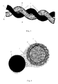
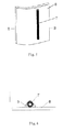
- Figure 5 is a top view structural schematic diagram of the dye sensitized solar cell used in embodiment 2 of the present invention.
- Figure 6 is a structural schematic diagram of the surface section taken along B-B in Figure 5 ;
- the working electrode of the dye sensitized solar cell comprises a filamentous conductive substrate 1 and a sensitized semi-conductor film. 2, wherein the sensitized semi-conductor film 2 is a porous film structure composed of semi-conductor particles of different sizes absorbed with sensitizing dye molecules, and the sensitized semi-conductor film 2 is coated on the outer surface of the filamentous conductive substrate 1.
- the sensitized semi-conductor film of the working electrode in the dye sensitized solar cell is prepared according to the following procedure: a semi-conductor material is spray coated and sintered several times on the filamentous conductive substrate, and the filamentous conductive substrate with the sintered semi-conductor material is placed in a dye for sensitization.
- the semi-conductor material is any semi-conductor material suitable for the working electrode of the dye sensitized solar cell, most typically nanoscale TiO 2 , ZnO and the like.
- the size and distribution of the nano particles are the same as those of the nano particles used for general dye sensitized solar cells.
- the application process thereof can follow conventional methods, such as spray coating, print coating, immersion coating, dip coating, doctor blade coating and the like.
- All of the dyes suitable for conventional dye sensitized solar cells are also suitable for sensitizing the semi-conductor material of the present working electrode, and completely identical sensitizing methods can be applied.
- the sensitized semi-conductor film 2 coated on the filamentous conductive substrate 1 can be 1 micron to 100 microns in thickness.
- the diameter of the filamentous conductive substrate 1 does not exceed 1 mm in general, and its apparent resistivity is ⁇ 100 ohm cm -1 .
- the filamentous conductive substrate 1 may have a filamentous structure made of metal filaments such as stainless steel filaments, alloy filaments and the like, or nonmetal conductive filaments such as carbon fibers, conductive polymers, inorganic conductive compound fibers and organic/inorganic composite conductive fibers or the like.
- a conductive material sheath can also be applied on the outer surface of the filamentous core made from conductive or nonconductive materials, or the filamentous conductive substrate 1 can also be made by coating a conductive material outside a gas medium or a vacuum medium.
- the filamentous conductive substrate can be formed not only by one filament, but also by two or more filaments collectively in a way of intimately arranging, wrapping around each other, twisting with each other, and the like.
- a stainless steel filament approximately 100 microns in diameter is used as the filamentous conductive substrate 1 of the working electrode; and a Pt filament approximately 100 microns in diameter is used as the counter electrode 4.
- the effective length of the cell prepared is 5 cm 2 .
- the detailed preparation procedure for the working electrode is as follows:
- the prepared stainless steel filament is washed with an organic solvent, such as acetone etc., and then washed with a substrate cleanser. Thereafter, the stainless steel filament is incandesced at 400°C-500°C for 15 minutes, and naturally cooled at room temperature. Under the roast of an infrared lamp, the incandesced stainless steel filament is spray coated with a solution of tetraethyl titanate/acetylacetone in ethanol, and then sintered again at 500°C for 30 minutes, and naturally cooled, thus a compact layer of semi-conductor material TiO 2 about 0.9 micron in thickness on the stainless steel filament is obtained.
- an organic solvent such as acetone etc.
- the semi-conductor material TiO 2 emulsion normally used in dye sensitized solar cells is spray coated on the compact layer, and then sintered at 500 °C for 30 minutes. After the above spray coating and sintering processes are repeated twice, the overall thickness of the semi-conductor material TiO 2 layer on the stainless steel filament reaches 4-9 microns.
- the sintered working electrode 6 comprising semi-conductor material TiO 2 is appropriately wrapped with the Pt filament counter electrode 5, it is placed in N3 dye/ethanol solution at a concentration of 3 ⁇ 10 -4 mole/L for 12 hours or more, and then removed from the solution and air dried.
- the sensitized semi-conductor film 2 is coated on the surface of the filamentous conductive substrate 1.
- the interfacial adhesion characteristic and the like it may be considered to physically or chemically modify the surface of the filament-structured filamentous conductive substrate 1, such as surface treatment, surface coating, etc.; for example, in order to improve the cell property, a compact layer 3 made of a semi-conductor or insulating material can further be coated on the surface of the filamentous conductive substrate 1 to prevent the electrolyte 5 from directly contacting with the filamentous conductive substrate 1.
- the methods for preparing the compact layer are sputtering, vacuum thermal evaporation plating, spray coating, and electrochemistry method.
- the electrolyte 5 After soaked in a standard electrolyte of normal liquid dye sensitized solar cells for 5 seconds, the electrolyte 5 is filled in the interspace between the filamentous working electrode 6 and the counter electrode 4, thus the dye sensitized solar cell of the present invention is produced.
- the cell property is measured under the condition of AM 1.5 (ASTM E892) and one time sun light intensity. The results obtained are: cell open circuit voltage is 580 mV, the short circuit current per centimeter length is 0.025 mA, and the overall photoelectric conversion efficiency is 0.91 %.
- the counter electrode can be a solid or hollow structure made of conductive materials, or it can consist of a core and several layers of sheath.
- the core and the sheath can be made from conductive or nonconductive materials, while the outermost layer of sheath coated is made of conductive materials.
- the conductive material used in the counter electrode 4 can be organic conductive material, inorganic conductive material (including metallic material) or organic/inorganic composite conductive material.
- a highly efficient catalyst layer can be added on the surface of the counter electrode 4, such as plating Pt on the stainless steel filament surface.
- the external surface of the counter electrode 4 can be a continuous or noncontinuous, compact or porous surface having a flexure or bending of any curvature.
- the filamentous working electrode 6 can be arranged with the outer surface of the counter electrode 4 by wrapping, intimately juxtaposition or attaching. The distance between the filamentous working electrode 6 and the outer surface of the counter electrode 4 is in a range of 0.001 mm to 1 cm.
- the preparation method for the filamentous working electrode 7 of the dye sensitized solar cell is the same as that for the filamentous working electrode 6 described in embodiment 1 of the present invention.
- the filamentous conductive substrate of the filamentous working electrode 7 utilizes carbon fibers with a diameter of 5 microns.
- the counter electrode 8 is a flexible planar conductor.
- the filamentous working electrode 7 can be arranged with the outer surface of the counter electrode 8 by intimately juxtaposition or attaching, and the interstice there between is filled with electrolyte 9.
- the electrolyte 9 can be any standard electrolyte system normally used in the preparation of dye sensitized solar cells. In the present embodiment, solid CuI electrolyte is used.
- the cell property is measured under the condition of AM 1.5 (ASTM E892) and one time sun light intensity. The results obtained are: cell open circuit voltage is 500 mV, the short circuit current per centimeter length reaches 0.030 mA, and the overall photoelectric conversion efficiency is 3%.
- the present invention discloses a working electrode of a dye sensitized solar cell and a dye sensitized solar cell structure based on it.
- the application conditions and examples described above are not for the purpose of limiting the present invention. Any skilled in the art can make various change and modification without departing from the spirit and scope of the present invention, therefore the range of protection of the present invention is defined by the scope of the claims.
Landscapes
- Chemical & Material Sciences (AREA)
- Chemical Kinetics & Catalysis (AREA)
- Electrochemistry (AREA)
- Engineering & Computer Science (AREA)
- Power Engineering (AREA)
- Microelectronics & Electronic Packaging (AREA)
- Hybrid Cells (AREA)
- Photovoltaic Devices (AREA)
Applications Claiming Priority (2)
| Application Number | Priority Date | Filing Date | Title |
|---|---|---|---|
| CNB2006101144547A CN100505325C (zh) | 2006-11-10 | 2006-11-10 | 染料敏化太阳能电池及其工作电极 |
| EP07816412A EP2091084A4 (de) | 2006-11-10 | 2007-09-21 | Farbstoffsensibilisierte solarbatterie und arbeitselektrode dafür |
Related Parent Applications (1)
| Application Number | Title | Priority Date | Filing Date |
|---|---|---|---|
| EP07816412.6 Division | 2007-09-21 |
Publications (2)
| Publication Number | Publication Date |
|---|---|
| EP2528101A2 true EP2528101A2 (de) | 2012-11-28 |
| EP2528101A3 EP2528101A3 (de) | 2013-01-02 |
Family
ID=39364172
Family Applications (2)
| Application Number | Title | Priority Date | Filing Date |
|---|---|---|---|
| EP12181001A Withdrawn EP2528101A3 (de) | 2006-11-10 | 2007-09-21 | Farbstoffsensibilisierte Solarzelle |
| EP07816412A Ceased EP2091084A4 (de) | 2006-11-10 | 2007-09-21 | Farbstoffsensibilisierte solarbatterie und arbeitselektrode dafür |
Family Applications After (1)
| Application Number | Title | Priority Date | Filing Date |
|---|---|---|---|
| EP07816412A Ceased EP2091084A4 (de) | 2006-11-10 | 2007-09-21 | Farbstoffsensibilisierte solarbatterie und arbeitselektrode dafür |
Country Status (5)
| Country | Link |
|---|---|
| US (1) | US20100037949A1 (de) |
| EP (2) | EP2528101A3 (de) |
| JP (1) | JP2010509715A (de) |
| CN (1) | CN100505325C (de) |
| WO (1) | WO2008055404A1 (de) |
Families Citing this family (9)
| Publication number | Priority date | Publication date | Assignee | Title |
|---|---|---|---|---|
| KR101027493B1 (ko) | 2009-12-28 | 2011-04-06 | 재단법인대구경북과학기술원 | 와이어 어레이를 이용한 태양광 전지 및 그 제조 방법 |
| KR100994902B1 (ko) * | 2010-04-06 | 2010-11-16 | 서울대학교산학협력단 | 플렉서블 염료감응 태양전지 및 이의 제조방법 |
| CN102568845B (zh) * | 2010-12-21 | 2015-10-28 | 北京大学 | 一种太阳能电池模块 |
| KR101418005B1 (ko) | 2013-01-16 | 2014-07-16 | 한국전기연구원 | 섬유편조를 이용한 염료감응형 태양전지 |
| KR101678172B1 (ko) * | 2013-01-16 | 2016-11-22 | 한국전기연구원 | 편조물을 이용한 직조형 염료감응형 태양전지 |
| CN103346017B (zh) * | 2013-07-17 | 2016-11-16 | 重庆大学 | 一种染料敏化太阳能电池光阳极及其制备方法 |
| CN104752779B (zh) | 2013-12-25 | 2017-04-26 | 华为技术有限公司 | 电池装置及电子设备 |
| CN106206031A (zh) * | 2015-05-08 | 2016-12-07 | 北京纳米能源与系统研究所 | 纤维染料敏化的光阳极、制备方法、电池及光伏器件 |
| CN106206030A (zh) * | 2015-05-08 | 2016-12-07 | 北京纳米能源与系统研究所 | 纤维染料敏化的光阳极、制备方法、电池及光伏器件 |
Family Cites Families (14)
| Publication number | Priority date | Publication date | Assignee | Title |
|---|---|---|---|---|
| JP3069160B2 (ja) * | 1991-07-26 | 2000-07-24 | 松下電器産業株式会社 | 高分子太陽電池 |
| DE4207659A1 (de) * | 1992-03-11 | 1993-09-16 | Abb Patent Gmbh | Verfahren zur herstellung einer photoelektrochemischen zelle sowie eine demgemaess hergestellte zelle |
| NO311317B1 (no) * | 1999-04-30 | 2001-11-12 | Thin Film Electronics Asa | Apparat omfattende elektroniske og/eller optoelektroniske kretser samt fremgangsmåte til å realisere og/eller integrerekretser av denne art i apparatet |
| US6913713B2 (en) * | 2002-01-25 | 2005-07-05 | Konarka Technologies, Inc. | Photovoltaic fibers |
| US7022910B2 (en) * | 2002-03-29 | 2006-04-04 | Konarka Technologies, Inc. | Photovoltaic cells utilizing mesh electrodes |
| DE10032286B4 (de) * | 2000-07-03 | 2014-04-03 | Textilforschungsinstitut Thüringen-Vogtland e.V. (TITV e.V.) | Lichtenergie in elektrische Energie wandelndes textiles Erzeugnis |
| JP2002151708A (ja) * | 2000-11-08 | 2002-05-24 | Rikogaku Shinkokai | 光起電力素子 |
| CN100530441C (zh) * | 2002-01-25 | 2009-08-19 | 科纳卡科技有限公司 | 光电纤维 |
| DE10305162A1 (de) * | 2002-03-12 | 2003-09-25 | Horst Ahlers | Textile Solarzellenanordnung |
| CN100345311C (zh) * | 2003-07-19 | 2007-10-24 | 鸿富锦精密工业(深圳)有限公司 | 一种太阳能电池 |
| JP4848661B2 (ja) * | 2005-03-30 | 2011-12-28 | 大日本印刷株式会社 | 色素増感型太陽電池用基材の製造方法および色素増感型太陽電池基材 |
| CN100355090C (zh) * | 2005-04-21 | 2007-12-12 | 中山大学 | 一种立体吸光的丝状集成染料敏化太阳电池 |
| CN1815759A (zh) * | 2005-12-13 | 2006-08-09 | 中山大学 | 一种有序纳米半导体阵列染料敏化太阳电池 |
| CN100420037C (zh) * | 2006-05-24 | 2008-09-17 | 武汉科技学院 | 一种太阳能电池柔性光阳极组件及其制备方法 |
-
2006
- 2006-11-10 CN CNB2006101144547A patent/CN100505325C/zh not_active Expired - Fee Related
-
2007
- 2007-09-21 EP EP12181001A patent/EP2528101A3/de not_active Withdrawn
- 2007-09-21 EP EP07816412A patent/EP2091084A4/de not_active Ceased
- 2007-09-21 US US12/514,298 patent/US20100037949A1/en not_active Abandoned
- 2007-09-21 WO PCT/CN2007/002796 patent/WO2008055404A1/zh not_active Ceased
- 2007-09-21 JP JP2009535545A patent/JP2010509715A/ja active Pending
Non-Patent Citations (1)
| Title |
|---|
| None |
Also Published As
| Publication number | Publication date |
|---|---|
| EP2091084A4 (de) | 2010-01-20 |
| EP2091084A1 (de) | 2009-08-19 |
| CN100505325C (zh) | 2009-06-24 |
| EP2528101A3 (de) | 2013-01-02 |
| CN101179099A (zh) | 2008-05-14 |
| WO2008055404A1 (en) | 2008-05-15 |
| US20100037949A1 (en) | 2010-02-18 |
| JP2010509715A (ja) | 2010-03-25 |
Similar Documents
| Publication | Publication Date | Title |
|---|---|---|
| EP2528101A2 (de) | Farbstoffsensibilisierte Solarzelle | |
| JP4698028B2 (ja) | 多重セル再生型光起電光電気化学デバイスにおける導通路を設ける方法 | |
| CN101719421B (zh) | 一种光阳极及其柔性太阳能电池 | |
| EP2395597B1 (de) | Farbstoffsensibilisierte solarzelle | |
| JP2002541641A (ja) | 単数セル及びマルチセル再生光電化学装置の封止及び電気接続を実施する方法 | |
| US20080210302A1 (en) | Methods and apparatus for forming photovoltaic cells using electrospray | |
| US20100243022A1 (en) | Dye-Sensitized Solar Cell Module | |
| TW200908355A (en) | Dye-sensitised solar cell module and manufacturing method thereof | |
| JPH11514787A (ja) | 光起電力セル電池及びその製造方法 | |
| KR102513067B1 (ko) | 염료 감응형 태양 전지 유닛, 염료 감응형 태양 전지 유닛을 포함하는 태양광 충전기 및 그 태양 전지 유닛을 제조하는 방법 | |
| WO2011009631A1 (en) | A method of manufacturing working electrodes for dye sensitised solar cells | |
| KR20060035598A (ko) | 광전기화학 장치 | |
| US9842705B2 (en) | Flexible dye-sensitized solar cell using fiber | |
| JP2002324590A (ja) | ナノ粒子酸化物太陽電池及びその製造方法とそれを利用した太陽電池モジュール及び透明電池ウィンドウ | |
| JP2007018909A (ja) | 光電変換装置の製造方法 | |
| JP5106866B2 (ja) | 光電変換素子 | |
| CN100505324C (zh) | 染料敏化太阳能电池及其工作电极结构 | |
| Koyasu et al. | Copper Sulfide Catalyzed Porous Fluorine‐Doped Tin Oxide Counter Electrode for Quantum Dot‐Sensitized Solar Cells with High Fill Factor | |
| JP5013741B2 (ja) | 光電変換装置及び光発電装置 | |
| JP6196547B2 (ja) | 光電極及びその製造方法、色素増感太陽電池 | |
| EP2625704B1 (de) | Vertikale elektrische verbindung für photelektrochemische zellen | |
| WO2005122322A1 (ja) | 色素増感型太陽電池及びその製造方法 | |
| JP4901194B2 (ja) | 光電変換装置及びその製造方法並びに光発電装置 | |
| JP2003163037A (ja) | 色素増感型光電気化学電池用電極およびそれを用いた色素増感型光電気化学電池 | |
| WO2013015067A1 (ja) | 光電変換装置、電子機器および建築物 |
Legal Events
| Date | Code | Title | Description |
|---|---|---|---|
| PUAI | Public reference made under article 153(3) epc to a published international application that has entered the european phase |
Free format text: ORIGINAL CODE: 0009012 |
|
| AC | Divisional application: reference to earlier application |
Ref document number: 2091084 Country of ref document: EP Kind code of ref document: P |
|
| AK | Designated contracting states |
Kind code of ref document: A2 Designated state(s): AT BE BG CH CY CZ DE DK EE ES FI FR GB GR HU IE IS IT LI LT LU LV MC MT NL PL PT RO SE SI SK TR |
|
| PUAL | Search report despatched |
Free format text: ORIGINAL CODE: 0009013 |
|
| AK | Designated contracting states |
Kind code of ref document: A3 Designated state(s): AT BE BG CH CY CZ DE DK EE ES FI FR GB GR HU IE IS IT LI LT LU LV MC MT NL PL PT RO SE SI SK TR |
|
| RIC1 | Information provided on ipc code assigned before grant |
Ipc: H01L 31/0224 20060101AFI20121129BHEP Ipc: H01L 31/04 20060101ALI20121129BHEP Ipc: H01G 9/20 20060101ALI20121129BHEP Ipc: H01L 31/18 20060101ALI20121129BHEP Ipc: H01L 51/42 20060101ALI20121129BHEP Ipc: H01L 51/48 20060101ALI20121129BHEP |
|
| STAA | Information on the status of an ep patent application or granted ep patent |
Free format text: STATUS: THE APPLICATION IS DEEMED TO BE WITHDRAWN |
|
| 18D | Application deemed to be withdrawn |
Effective date: 20130403 |