EP2528198A2 - Rotor und Motor - Google Patents
Rotor und Motor Download PDFInfo
- Publication number
- EP2528198A2 EP2528198A2 EP12167758A EP12167758A EP2528198A2 EP 2528198 A2 EP2528198 A2 EP 2528198A2 EP 12167758 A EP12167758 A EP 12167758A EP 12167758 A EP12167758 A EP 12167758A EP 2528198 A2 EP2528198 A2 EP 2528198A2
- Authority
- EP
- European Patent Office
- Prior art keywords
- permanent magnets
- rotor
- rotor core
- module
- connection part
- Prior art date
- Legal status (The legal status is an assumption and is not a legal conclusion. Google has not performed a legal analysis and makes no representation as to the accuracy of the status listed.)
- Ceased
Links
Images





Classifications
-
- H—ELECTRICITY
- H02—GENERATION; CONVERSION OR DISTRIBUTION OF ELECTRIC POWER
- H02K—DYNAMO-ELECTRIC MACHINES
- H02K1/00—Details of the magnetic circuit
- H02K1/06—Details of the magnetic circuit characterised by the shape, form or construction
- H02K1/22—Rotating parts of the magnetic circuit
- H02K1/27—Rotor cores with permanent magnets
- H02K1/2706—Inner rotors
- H02K1/272—Inner rotors the magnetisation axis of the magnets being perpendicular to the rotor axis
- H02K1/274—Inner rotors the magnetisation axis of the magnets being perpendicular to the rotor axis the rotor consisting of two or more circumferentially positioned magnets
- H02K1/2753—Inner rotors the magnetisation axis of the magnets being perpendicular to the rotor axis the rotor consisting of two or more circumferentially positioned magnets the rotor consisting of magnets or groups of magnets arranged with alternating polarity
- H02K1/276—Magnets embedded in the magnetic core, e.g. interior permanent magnets [IPM]
- H02K1/2766—Magnets embedded in the magnetic core, e.g. interior permanent magnets [IPM] having a flux concentration effect
- H02K1/2773—Magnets embedded in the magnetic core, e.g. interior permanent magnets [IPM] having a flux concentration effect consisting of tangentially magnetized radial magnets
-
- H—ELECTRICITY
- H02—GENERATION; CONVERSION OR DISTRIBUTION OF ELECTRIC POWER
- H02K—DYNAMO-ELECTRIC MACHINES
- H02K1/00—Details of the magnetic circuit
- H02K1/02—Details of the magnetic circuit characterised by the magnetic material
-
- H—ELECTRICITY
- H02—GENERATION; CONVERSION OR DISTRIBUTION OF ELECTRIC POWER
- H02K—DYNAMO-ELECTRIC MACHINES
- H02K1/00—Details of the magnetic circuit
- H02K1/06—Details of the magnetic circuit characterised by the shape, form or construction
- H02K1/22—Rotating parts of the magnetic circuit
- H02K1/27—Rotor cores with permanent magnets
- H02K1/2706—Inner rotors
- H02K1/272—Inner rotors the magnetisation axis of the magnets being perpendicular to the rotor axis
- H02K1/274—Inner rotors the magnetisation axis of the magnets being perpendicular to the rotor axis the rotor consisting of two or more circumferentially positioned magnets
- H02K1/2753—Inner rotors the magnetisation axis of the magnets being perpendicular to the rotor axis the rotor consisting of two or more circumferentially positioned magnets the rotor consisting of magnets or groups of magnets arranged with alternating polarity
- H02K1/278—Surface mounted magnets; Inset magnets
-
- H—ELECTRICITY
- H02—GENERATION; CONVERSION OR DISTRIBUTION OF ELECTRIC POWER
- H02K—DYNAMO-ELECTRIC MACHINES
- H02K1/00—Details of the magnetic circuit
- H02K1/06—Details of the magnetic circuit characterised by the shape, form or construction
- H02K1/22—Rotating parts of the magnetic circuit
- H02K1/28—Means for mounting or fastening rotating magnetic parts on to, or to, the rotor structures
-
- H—ELECTRICITY
- H02—GENERATION; CONVERSION OR DISTRIBUTION OF ELECTRIC POWER
- H02K—DYNAMO-ELECTRIC MACHINES
- H02K21/00—Synchronous motors having permanent magnets; Synchronous generators having permanent magnets
- H02K21/12—Synchronous motors having permanent magnets; Synchronous generators having permanent magnets with stationary armatures and rotating magnets
- H02K21/14—Synchronous motors having permanent magnets; Synchronous generators having permanent magnets with stationary armatures and rotating magnets with magnets rotating within the armatures
-
- H—ELECTRICITY
- H02—GENERATION; CONVERSION OR DISTRIBUTION OF ELECTRIC POWER
- H02K—DYNAMO-ELECTRIC MACHINES
- H02K1/00—Details of the magnetic circuit
- H02K1/06—Details of the magnetic circuit characterised by the shape, form or construction
- H02K1/22—Rotating parts of the magnetic circuit
- H02K1/27—Rotor cores with permanent magnets
- H02K1/2706—Inner rotors
- H02K1/272—Inner rotors the magnetisation axis of the magnets being perpendicular to the rotor axis
- H02K1/274—Inner rotors the magnetisation axis of the magnets being perpendicular to the rotor axis the rotor consisting of two or more circumferentially positioned magnets
- H02K1/2753—Inner rotors the magnetisation axis of the magnets being perpendicular to the rotor axis the rotor consisting of two or more circumferentially positioned magnets the rotor consisting of magnets or groups of magnets arranged with alternating polarity
- H02K1/276—Magnets embedded in the magnetic core, e.g. interior permanent magnets [IPM]
Definitions
- the following description relates to a rotor and a motor providing high power operation at high level driving speeds.
- a motor is classified into a permanent magnet synchronous motor (PMSM), an induction motor, a switched reluctance motor (SRM), etc.
- PMSM uses a permanent magnet, has a high level of power density, a compact sized structure, and superior operation efficiency.
- the PMSM is widely applied to a motor for hybrid vehicles or electric vehicles.
- the magnet used for the PMSM is formed using rare earth resources.
- the rare earth resource magnet may be a Neodymium (NdFeB) magnet having superior residual magnetism (Br) and coercive force (Hc).
- NdFeB Neodymium
- Hc coercive force
- the scarcity of rare earth resources causes high costs and wide cost fluctuations of the rare earth resource magnet.
- a rotor including a rotor core and a module.
- the rotor core is formed at a center thereof with a hole coupled to a shaft.
- the module is configured to be coupled to the rotor core and comprises a pair of first permanent magnets, which are space apart from each other, and a first connection part connecting ends of the first permanent magnets to each other.
- the first connection part may connect ends of the first permanent magnets, adjacent to an inner side of the rotor core, to each other.
- the first connection part may be spaced apart from an inner surface of the rotor core.
- the module may include a pair of second permanent magnets spaced apart from the first permanent magnets, and a second connection part connecting ends of the second permanent magnets to each other.
- the module may include a third permanent magnet which is disposed at an outer side of the rotor core between the first permanent magnets.
- the module may be provided in an even number of modules, and the even number of modules may be disposed on the rotor core while being spaced apart from each other and being spaced apart from an inner surface of the rotor core.
- the module may be buried in the rotor core.
- the first connection part may have a center part, which includes a permanent magnet or air, and a remaining part, which includes non-magnetic material or air.
- the rotor core may include soft magnetic material.
- a rotor including a rotor core and a plurality of modules.
- the rotor core is formed at a center thereof with a hole coupled to a shaft.
- Each of the modules is coupled to the rotor core while being spaced apart from an inner surface of the rotor core.
- the modules are provided in an even number of modules which are spaced apart from each other and include a pair of first permanent magnets spaced apart from each other and a first connection part connecting ends of the first permanent magnets that are adjacent to the inner surface of the rotor core to each other.
- a motor comprising a rotor, a shaft and a stator.
- the rotor includes a rotor core, which is formed at a center thereof with a hole coupled to a shaft.
- the rotor also includes a module, which is coupled to the rotor core, and comprises a pair of first permanent magnets spaced apart from each other and a first connection part connecting ends of the first permanent magnets to each other.
- the shaft is coupled to the hole.
- the stator is spaced apart from the rotor and comprises at least one slot around which a coil is wound.
- the first connection part may connect ends of the first permanent magnets to each other, the ends adjacent to an inner surface of the rotor core, and the first connection part is spaced apart from the inner surface of the rotor core.
- the module may include a pair of second permanent magnets spaced apart from the first permanent magnets, and a second connection part connecting ends of the second permanent magnets to each other.
- the module may include a third permanent magnet which is disposed at an outer side of the rotor core between the first permanent magnets.
- the module may be provided in an even number of modules and the even number of modules are disposed on the rotor core while being spaced apart from each other and being spaced apart from an inner surface of the rotor core.
- the first connection part may have a center part, which includes a permanent magnet or air, and a remaining part, which includes non-magnetic material or air.
- the rotor core may include soft magnet material.
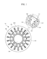
- FIG. 1 is a cross sectional view showing the configuration of a motor according to an exemplary embodiment.
- a motor 10 includes a stator 100, a coil 110, a rotor 120 and a shaft 130.
- the stator 100 includes at least one slot.
- a coil 110 is disposed of in the at least one slot.
- the stator 100 is fixed while being spaced apart from the rotor 120.
- the spacing between the stator 100 and the rotor 120 may be greater than .2 mm and less than 1.5 mm.
- the coil 110 is wound around teeth 101.
- the rotor may have a relative permeability (Mu) of between 1.0 and 1.5.
- the rotor 120 may include a module 140 and a rotor core 150.
- the module 140 may include a pair of first permanent magnets 141 and a first connection part 142.
- the pair of first permanent magnets 141 are disposed in various forms.
- the pair of first permanent magnets may be disposed in parallel to each other or in the form of an alphabet V.
- the pair of first permanent magnets 141 may include permanent magnets or hard magnetic material.
- the pair of first permanent magnets 141 may also include magnets which have a low Br value such as ferrite magnets as well as alloys of iron, nickel, ferrite, cobalt, and other magnetic materials such as lodestone.
- the pair of first permanent magnets may have a Br value between 0.3 Tesla and 1.5 Tesla. When permanent magnets having a higher Br value are used in the rotor structure, the number of required magnets will be reduced compared to when ferrite based magnets are used, without changing the entire structure of the rotor.
- the pair of first permanent magnets 141 may be magnetized in opposite directions to each other along the circumferential direction.
- the pair of the first permanent magnets 141 may be magnetized in a direction proceeding from the outside 160 of the first permanent magnet 141 to the inside of the first permanent magnet by passing through the first permanent magnet 141.
- the first permanent magnets 141 may be magnetized in a direction from the inside 161 of the first permanent magnet 141 to the outside of the first permanent magnet 141 by passing through the first permanent magnet 141.
- the first connection part 142 connects ends of the first permanent magnets 141 to each other.
- the first connection part 142 may connect ends of the first permanent magnets 141 adjacent to the inner side ofthe rotor core 150 to each other.
- the first connection part 142 is disposed while being spaced apart from the inner surface of the rotor core 150.
- the first connection part 142 may be spaced by a predetermined interval from the inner surface ofthe rotor core 150.
- the length in a circumferential direction of the first connection part 142 depends on the thickness in the radial direction of the first permanent magnets 141, and the thickness in radial direction ofthe first connection part 142 may be half the thickness in circumferential direction ofthe permanent magnets 141.
- the first connection part 142 may include non-magnetic material or air. In the case that the first connection part 142 includes air, the first connection part 142 may include an empty space. Alternatively, the first connection part 142 may include a center part, which includes magnetic material, and a remaining part, which includes non-magnetic material or air. The magnetic material of the first connection part 142 may be the same material as the first permanent magnet 141 or a different material.
- the rotor 120 may include an even number of modules 140.
- One of the even number modules 140 forms an north (N) pole at an outer side of the rotor core 150 and a nearby module forms a south (S) pole at an outer side of the rotor core 150.
- N north
- S south
- the detailed shape of the modules will be described with reference to FIG. 3 .
- the module 140 may be coupled to the rotor core 150 through various schemes including burying in the rotor core 150.
- the rotor core 150 corresponds to a part of the rotor 120 except for the module 140.
- the rotor core 150 may be formed at the center thereof with a hole and include soft magnetic material.
- the soft magnetic material may be a thin electric steel sheet.
- the rotor core may be formed by stacking thin electric steel sheets or soft magnetic composite (SMC) formed by insulating small magnetic particles each having a size of several ⁇ meters.
- SMC soft magnetic composite
- the shaft 130 is inserted in the hole, so that the shaft 130 is coupled to the rotor core 150. Accordingly, the shaft 130 rotates by the rotation of the rotor 120.
- the shaft 130 includes non-magnetic material.
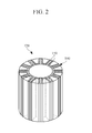
- FIG. 2 is a perspective view showing the configuration of a rotor according to an exemplary embodiment.
- the rotor 120 may include the module 140 and the rotor core 150.
- the module 140 may be buried in the rotor core 150 to be coupled to the rotor core 150.
- the method of coupling the module 140 to the rotor core 150 is not limited thereto and may be implemented through various schemes.
- FIG. 3 is a cross sectional view partially showing the motor to describe the magnetization direction passing through permanent magnets according to an exemplary embodiment.
- the motor 10 includes the stator 100, the rotor 120 and the shaft 130.
- a q-axis is referred to as an axis proceeding from the center of rotation and passing between adjacent two modules
- a d-axis is referred to as an axis proceeding from the center of rotation and passing through the inside of the module.
- the rotor 120 includes a first module 200, a second module 210 and a third module 220.
- the first module 200 includes a pair of permanent magnets, the facing inner sides of which are magnetized with N poles. Accordingly, the magnetic flux, which is generated by the permanent magnets, flows in the direction passing from the outside of the permanent magnets of the first module 200 to the inside of the module through the permanent magnets of the first module 200 and then proceeds to the stator 100.
- the magnetic flux having reached the stator 100 flows to the second module 210 or a module (not shown) disposed on the left side of the first module 200 by passing through the stator 100.
- the first module 200 serves as an N pole.
- the second module 210 includes a pair of permanent magnets, the facing inner sides of which are magnetized with S poles. Accordingly, the magnetic flux, which is generated by the permanent magnets, flows in the direction passing from the stator 100 to the inside of the permanent magnets of the second module 210, passes through the permanent magnets of the second module 210 to the outside of the permanent magnets of the second module 210, and then proceeds to other modules 200 and 220. The magnetic flux having reached other modules 200 and 220 may flow to the inside of the permanent magnets by passing through the permanent magnets. In this case, the second module 210 serves as an S pole.
- the third module 220 includes a pair of permanent magnets, the facing inner sides of which are magnetized with N poles. Accordingly, the magnetic flux, which is generated by the permanent magnets of the third module 220, flows in the direction passing from the outside of the permanent magnets of the third module 220 to the inside of the module through the permanent magnets of the third module 220 and then proceeds to the stator 100. The magnetic flux having reached the stator 100 flows to the second module 210 or a module (not shown) disposed on the right side of the third module 220 by passing through the stator 100. In this case, the third module 220 serves as an N pole.
- each of the modules 200, 210 and 220 included in the rotor 120 may be provided in even number.
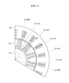
- FIG. 4 is a cross sectional view of a part of the motor showing the path of a magnetic flux generated by a d-axis current and a q-axis current according to an exemplary embodiment.
- the motor 10 includes the stator 100, the rotor 120 and the shaft 130.
- a q-axis is referred to as an axis proceeding from the center of rotation and sequentially passing between adjacent two modules
- a d-axis is referred to as an axis proceeding from the center of rotation and passing through the inside of the module.
- Torque P n ⁇ f ⁇ i q + L d - L q ⁇ i d ⁇ i q
- P n represents the number of pair poles and ⁇ f represents the flux linkage by a permanent magnet
- i d and L d represent the d-axis current and the d-axis inductance, respectively
- iq and Lq represent the q-axis current and the q-axis inductance, respectively.
- the first term corresponding to P n * ⁇ f *i q represents a magnetic torque and the second term corresponding to P n *(L d - Lq)*i d *i q represents a reluctance torque.
- the q-axis current is dominant, so the torque of the motor is substantially dependent on the magnetic torque.
- the q-axis current is reduced and the d-axis current of negative (-) is increased, so that the torque of the motor is more dependent on the reluctance torque.
- the q-axis inductance (Lq) is greater than the d-axis inductance (L d ), the d-axis current (i d ) is negative and the q-axis current (iq) is positive. Since the q-axis inductance (Lq) is greater than the d-axis inductance (L d ), the d-axis inductance (L d ) minus the q-axis inductance (Lq) is a negative value. Since the d-axis current (i d ) is negative and the q-axis current (iq) is positive, the reluctance torque has a positive value.
- the path of the magnetic flux passes through a gap between the stator 100, the rotor core 150, and a part of the rotor core 150. That is, in the path of the magnetic flux generated by the q-axis current, only the gap between stator 100 and the rotor core 150 serves as a factor impeding the flow of the magnetic flux, so that the magnetic flux generated per electric current is great. That is, the q-axis inductance (Lq) is great.
- the path of a magnetic flux generated by the d-axis current passes through two permanent magnets in addition to a gap between the stator 100 and the rotor core 150. That is, the gap and the two permanent magnets exist in the path of the magnetic flux generated by the d-axis current, so that resistance to the flow of the magnetic flux is great. Accordingly, the magnetic flux generated per electric current is small. That is, the d-axis inductance (L d ) is small.
- the example of the rotor structure enables the q-axis inductance to be increased, so that the value ofL d - L q is increased, and thus the reluctance torque is increased. Since the reluctance torque, which has a great influence on the total torque of the motor at high level driving speeds, is increased, the motor maintains high power operation even at high level driving speeds.
- the motor 140 includes the first connection part 142 including non-magnetic material or air, thereby preventing the magnetic flux generated from the permanent magnet 141 from leaking to the inner side of the rotor core 150. That is, the first connection part 142 prevents some of the magnetic flux generated by the permanent magnet 141 from leaking to the inner side of the rotor core 150, thereby improving the performance of the motor 10.
- the non-magnetic material may be a material having a permeability of about "1" and may be made of aluminum, plastic, fiber reinforced plastic (FRP), or the like may be used.
- FIGS. 5A, 5B and 5C are views showing a module according to aspects of the exemplary embodiments.
- the range of the length, width, distance, and angles in which the first permanent magnets 141 and the first connection part 142 are arranged may vary.
- the module 140 of the rotor 120 may include a pair of first permanent magnets 500a and a first connection part 510a.
- the first connection part 510a connects ends of the pair of first permanent magnets 500a to each other.
- the first connection part 510a connects the ends adjacent to the inner side of the rotor core 150 of the first permanent magnets 500a to each other.
- the first connection part 510a includes non-magnetic material or air.
- the first connection part 510a is spaced apart from the inner surface of the rotor core 150.
- the inner sides of the first permanent magnets 500 which face each other may be magnetized with N poles or S poles. Therefore, the magnetization is achieved in the direction proceeding from the outside of the first permanent magnets 500a to the inside of the first permanent magnets 500a by passing through the first permanent magnets 500a, or the opposite direction.
- the module 140 of the rotor 120 may include a pair of first permanent magnets 500b, a first connection part 510b, a pair of second permanent magnets 520b and a second connection part 530b.
- the first connection part 510b connects ends of the first permanent magnets 500b to each other.
- the first connection part 510b connects the ends of the first permanent magnets 500b adjacent to the inner side ofthe rotor core 150 to each other.
- the first connection part 510b may include non-magnetic material or air.
- the first connection part 510b is spaced from the inner surface of the rotor core 150.
- the first connection part 510b may include a center, referred to as connection part 510c in FIG. 5C , which is formed using hard magnetic material.
- the pair of second permanent magnets 520b is spaced apart from the pair of the first permanent magnets 500b.
- the second connection part 530b connects the ends of the second permanent magnets 520b to each other.
- the second connection part 530b may connect the ends of the second permanent magnets 520b adjacent to the inner side of the rotor core 150 to each other.
- the second connection part 530b may include non-magnetic material or air.
- the second connection part 530b is spaced apart from the inner surface of the rotor core 150.
- the module 140 including the first permanent magnets 500b and the first connection part 510b may further include another module including the second permanent magnets 520b and the second connection part 530b.
- the inner sides of the first permanent magnets 500b which face each other may be magnetized with N poles or S poles.
- the inner sides of the second permanent magnet 520b which face each other are magnetized with the same poles as those of the first permanent magnets 500b.
- the magnetization is achieved in the direction proceeding from the outside of the second permanent magnets 520b to the inside of the first permanent magnets 500b by passing through the second permanent magnets 520b and the first permanent magnets 500b, or the opposite direction.
- the magnetic flux generated by the permanent magnets is increased and the performance of the motor 10 is improved.
- the increase of the number of the permanent magnets increases the paths of magnetic flux generated by q-axis current, so that the q-axis inductance is increased and the performance of the motor 10 is improved.
- the module 140 of the rotor 120 includes a pair of permanent magnets 500c and first connection parts including a center part 510c and remaining parts 520c.
- the first connection parts 510c and 520c connect ends of the first permanent magnets 500c to each other.
- the first connection parts 510c and 520c connect ends of the first permanent magnets 500c adjacent to the inside ofthe rotor core 150 to each other.
- the first connection parts 510c and 520c are spaced apart from the inner surface of the rotor core 150.
- the center part 510c of the first connection parts 510c and 520c includes a permanent magnet or air, and the remaining parts 520c include non-magnetic material or air.
- Facing inner sides of the first permanent magnets 500c may be magnetized with N poles or S poles, and the center part 510c is magnetized with a predetermined pole capable of increasing the total magnetic flux generated in the module 140.
- the inner side of the center part 510c of the first connection parts has the same pole as the facing inner sides of the first permanent magnets 500c.
- the magnetization is achieved in the direction proceeding from the outside of the first permanent magnets 500c to the inside of the first permanent magnets 500c by passing through the first permanent magnets 500c, or in the opposite direction.
- the adding of the center part 510c formed using a hard magnetic material magnet increases the magnetic flux generated by the permanent magnets 500c. Accordingly, the performance of the motor 10 is improved.
- the module 140 of the rotor 120 includes a pair of first permanent magnets 500d, a first connection part 510d and a third permanent magnet 520d.
- the first connection part 510d connects ends of the first permanent magnets 500d to each other.
- the first connection part 510d connects ends of the first permanent magnets 500d adjacent to the inner side ofthe rotor core 150 to each other.
- the first connection part 510d includes non-magnetic material or air.
- the first connection part 510d is spaced apart from the inner surface of the rotor core 150.
- the third permanent magnet 520d is disposed at an outer side of the rotor core 150 between the first permanent magnets 500d.
- the first permanent magnets 500d needs to be magnetized such that N poles or S poles face each other and the third permanent magnet 520d needs to be magnetized in the direction capable of increasing the total magnetic flux generated in the module 140.
- facing inner sides of the first permanent magnets 500d are magnetized with N poles or S poles, and the third permanent magnet 520d has a pole capable of increasing the total magnetic flux generated in the module 140.
- the inner sides of the first permanent magnets 500d are magnetized with N poles
- a lower side of the third permanent magnet 520d is magnetized with an N pole
- an upper side of the third permanent magnet 520d is magnetized with an S pole.
- the adding of the third permanent magnet 520d increases the magnetic flux generated by the permanent magnets 500d. Accordingly, the performance of the motor 10 is improved.
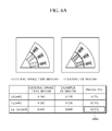
- FIGS. 6A , 6B and 6C are views used to explain the performance of the motor according to aspects of the exemplary embodiments.
- a simulation result is provided through a simulation software program name Maxwell for electromagnetic design of a motor.
- a general spoke type motor has a d-axis inductance (L d ) of 0.160 mH, a q-axis inductance (Lq) of 0.202 mH, and has an inductance difference (Lq - L d ) of 0.042 mH.
- the motor according to an exemplary embodiment which uses the same amount of magnets as the general motor, has a d-axis inductance (L d ) of 0.159 mH, a q-axis inductance (Lq) of 0.228 mH, and has an inductance difference (Lq -L d ) of 0.069 mH.
- the inductance difference (Lq -L d ) of the motor of the exemplary embodiment is greater than that of the general spoke type motor by 62.8% as shown in 600a in FIG. 6A . That is, the motor according to an exemplary embodiment has an inductance difference (Lq -L d ) greater than that of the general motor.
- the motor according to an exemplary embodiment has an inductance difference (Lq -L d ) greater than that of the general motor, so that the reluctance torque is increased.
- the reluctance torque has a greater influence on the total torque of the motor than the magnetic torque does. Accordingly, the motor according to an exemplary embodiment can provide higher power operation at high level driving speeds than the general spoke type motor.
- FIG. 6B shows the torque of a motor with rise of rotational speed of the motor.
- the motor according to an exemplary embodiment shows a smooth torque drop as compared with the general spoke type motor (see 600b of FIG. 6B ). That is, the motor according to an exemplary maintains a high level of torque even if the RPM rises. Meanwhile, the torque of the general spoke type motor rapidly drops with a rise of RPM (see 610b of FIG. 6B ).
- the example of the motor maintains a high level of torque even if the driving speed is increased.
Landscapes
- Engineering & Computer Science (AREA)
- Power Engineering (AREA)
- Permanent Field Magnets Of Synchronous Machinery (AREA)
- Iron Core Of Rotating Electric Machines (AREA)
- Permanent Magnet Type Synchronous Machine (AREA)
- Synchronous Machinery (AREA)
Applications Claiming Priority (1)
| Application Number | Priority Date | Filing Date | Title |
|---|---|---|---|
| KR1020110050342A KR101786922B1 (ko) | 2011-05-26 | 2011-05-26 | 로터 및 구동 모터 |
Publications (2)
| Publication Number | Publication Date |
|---|---|
| EP2528198A2 true EP2528198A2 (de) | 2012-11-28 |
| EP2528198A3 EP2528198A3 (de) | 2015-10-28 |
Family
ID=46046026
Family Applications (1)
| Application Number | Title | Priority Date | Filing Date |
|---|---|---|---|
| EP12167758.7A Ceased EP2528198A3 (de) | 2011-05-26 | 2012-05-11 | Rotor und Motor |
Country Status (5)
| Country | Link |
|---|---|
| US (1) | US9083219B2 (de) |
| EP (1) | EP2528198A3 (de) |
| JP (1) | JP6423991B2 (de) |
| KR (1) | KR101786922B1 (de) |
| CN (1) | CN102801237B (de) |
Cited By (2)
| Publication number | Priority date | Publication date | Assignee | Title |
|---|---|---|---|---|
| EP3410574A1 (de) * | 2017-06-02 | 2018-12-05 | Hamilton Sundstrand Corporation | Hybridsynchronmaschine |
| CN119675294A (zh) * | 2025-01-17 | 2025-03-21 | 南京师范大学 | 组合材料永磁体和转子冲片的低电压调整率发电机转子 |
Families Citing this family (23)
| Publication number | Priority date | Publication date | Assignee | Title |
|---|---|---|---|---|
| US9882440B2 (en) | 2012-10-15 | 2018-01-30 | Regal Beloit America, Inc. | Radially embedded permanent magnet rotor and methods thereof |
| US9246364B2 (en) | 2012-10-15 | 2016-01-26 | Regal Beloit America, Inc. | Radially embedded permanent magnet rotor and methods thereof |
| US9362792B2 (en) | 2012-10-15 | 2016-06-07 | Regal Beloit America, Inc. | Radially embedded permanent magnet rotor having magnet retention features and methods thereof |
| US9831727B2 (en) * | 2012-10-15 | 2017-11-28 | Regal Beloit America, Inc. | Permanent magnet rotor and methods thereof |
| JP6074290B2 (ja) * | 2013-03-04 | 2017-02-01 | アイチエレック株式会社 | 回転子および永久磁石電動機 |
| US9837881B2 (en) * | 2013-04-16 | 2017-12-05 | Siemens Aktiengesellschaft | Method for producing an individual-segment rotor for an electric machine |
| EP2793365A1 (de) * | 2013-04-16 | 2014-10-22 | Siemens Aktiengesellschaft | Einzelsegmentläufer mit durch Biegeträger gehaltenen Einzelsegmenten und Herstellungsverfahren |
| KR102040147B1 (ko) * | 2013-06-20 | 2019-11-04 | 삼성전자주식회사 | 전기 모터의 회전자 및 이를 채용한 모터 |
| JP5906360B2 (ja) | 2013-08-09 | 2016-04-20 | 株式会社 成田 | 磁力回転装置、電動機、および電動発電機 |
| CN104682650A (zh) * | 2013-11-28 | 2015-06-03 | 德昌电机(深圳)有限公司 | 电机转子以及具有该电机转子的无刷电机 |
| CN106300730B (zh) * | 2015-06-08 | 2019-01-01 | 珠海格力节能环保制冷技术研究中心有限公司 | 电机转子及具有其的电机 |
| DE102016207800A1 (de) * | 2016-05-04 | 2017-11-09 | Volkswagen Aktiengesellschaft | Rotor für einen Elektromotor |
| FR3064837B1 (fr) * | 2017-04-03 | 2020-01-17 | Moving Magnet Technologies | Rotor pour machine electrique a aimants permanents internes |
| CN107681858A (zh) * | 2017-09-18 | 2018-02-09 | 东南大学 | 一种聚磁型磁阻偏移式电机 |
| CN107733112A (zh) * | 2017-09-18 | 2018-02-23 | 南京理工大学 | 一种超高速永磁同步电机转子结构 |
| CN108321954B (zh) * | 2018-03-16 | 2020-10-23 | 珠海格力节能环保制冷技术研究中心有限公司 | 转子结构、永磁辅助同步磁阻电机及电动汽车 |
| CN110061602B (zh) * | 2018-12-26 | 2020-07-24 | 南方科技大学 | 转子结构及永磁激磁电机 |
| DE102019102540A1 (de) * | 2019-02-01 | 2020-08-06 | Bayerische Motoren Werke Aktiengesellschaft | Eingebettete Magnetanordnung für permanenterregte elektrische Maschinen |
| CN211670689U (zh) * | 2019-07-19 | 2020-10-13 | 菲舍尔和佩克尔应用有限公司 | 电动马达和包括电动马达的洗衣机 |
| GB2586784B (en) | 2019-08-30 | 2022-05-04 | Computionics Ltd | Improvements to smoke detectors |
| JP2021168536A (ja) * | 2020-04-09 | 2021-10-21 | 大銀微系統股▲分▼有限公司Hiwin Mikrosystem Corp. | 永久磁石式モータの回転子構造 |
| CN112771762B (zh) * | 2020-04-30 | 2023-02-03 | 华为技术有限公司 | 转子、永磁电机、电机驱动系统以及汽车 |
| JP7478104B2 (ja) * | 2021-01-08 | 2024-05-02 | 株式会社アイシン | ロータコア |
Family Cites Families (20)
| Publication number | Priority date | Publication date | Assignee | Title |
|---|---|---|---|---|
| JPH0739091A (ja) | 1993-07-19 | 1995-02-07 | Toyota Motor Corp | 同期機のロータ構造および同期型モータ |
| JP3605475B2 (ja) * | 1996-08-06 | 2004-12-22 | 松下電器産業株式会社 | 永久磁石同期電動機 |
| TW364234B (en) * | 1997-04-14 | 1999-07-11 | Sanyo Electric Co | Rotor for an electric motor |
| JP2000060038A (ja) | 1998-08-05 | 2000-02-25 | Toyota Motor Corp | 電動機 |
| JP2000102202A (ja) * | 1998-09-22 | 2000-04-07 | Aichi Emerson Electric Co Ltd | 永久磁石形電動機の回転子 |
| JP3172506B2 (ja) * | 1999-03-18 | 2001-06-04 | 株式会社東芝 | 永久磁石式リラクタンス型回転電機 |
| JP2001145283A (ja) * | 1999-11-19 | 2001-05-25 | Toyota Motor Corp | 永久磁石式回転機の回転子 |
| JP2002186244A (ja) | 2000-12-15 | 2002-06-28 | Mitsubishi Heavy Ind Ltd | 永久磁石型リニアモータ |
| JP4680442B2 (ja) * | 2001-08-10 | 2011-05-11 | ヤマハ発動機株式会社 | モータの回転子 |
| JP2003088019A (ja) * | 2001-09-10 | 2003-03-20 | Fujitsu General Ltd | 永久磁石電動機 |
| JP3996417B2 (ja) * | 2002-03-26 | 2007-10-24 | アイチエレック株式会社 | 永久磁石電動機 |
| JP2004096850A (ja) * | 2002-08-30 | 2004-03-25 | Toyo Electric Mfg Co Ltd | 誘導始動形同期回転電機の回転子 |
| DE10318624A1 (de) * | 2003-04-24 | 2004-11-25 | Minebea Co., Ltd. | Rotorkörper für einen Elektromotor |
| EP1471621A3 (de) * | 2003-04-24 | 2005-12-14 | Minebea Co., Ltd. | Rotorkörper für einen Elektromotor |
| DE10345417A1 (de) * | 2003-09-30 | 2005-05-12 | Minebea Co Ltd | Rotorköper für einen Elektromotor |
| US7518278B2 (en) * | 2004-05-18 | 2009-04-14 | Ut-Battelle, Llc | High strength undiffused brushless machine and method |
| JP2006014457A (ja) | 2004-06-24 | 2006-01-12 | Fanuc Ltd | 同期電動機 |
| KR100591338B1 (ko) * | 2004-08-26 | 2006-06-19 | 엘지전자 주식회사 | 영구자석 보조형 동기 릴럭턴스 모터 및 그 착자방법 |
| US7851958B2 (en) * | 2006-06-12 | 2010-12-14 | Remy International, Inc. | Electric machine with interior permanent magnets |
| US7902710B2 (en) * | 2008-10-01 | 2011-03-08 | Caterpillar Inc. | Electric machine |
-
2011
- 2011-05-26 KR KR1020110050342A patent/KR101786922B1/ko not_active Expired - Fee Related
-
2012
- 2012-04-17 US US13/449,104 patent/US9083219B2/en active Active
- 2012-05-11 EP EP12167758.7A patent/EP2528198A3/de not_active Ceased
- 2012-05-21 CN CN201210158775.2A patent/CN102801237B/zh not_active Expired - Fee Related
- 2012-05-25 JP JP2012120085A patent/JP6423991B2/ja active Active
Non-Patent Citations (1)
| Title |
|---|
| None |
Cited By (3)
| Publication number | Priority date | Publication date | Assignee | Title |
|---|---|---|---|---|
| EP3410574A1 (de) * | 2017-06-02 | 2018-12-05 | Hamilton Sundstrand Corporation | Hybridsynchronmaschine |
| US10715017B2 (en) | 2017-06-02 | 2020-07-14 | Hamilton Sundstrand Corporation | Hybrid synchronous machines |
| CN119675294A (zh) * | 2025-01-17 | 2025-03-21 | 南京师范大学 | 组合材料永磁体和转子冲片的低电压调整率发电机转子 |
Also Published As
| Publication number | Publication date |
|---|---|
| KR101786922B1 (ko) | 2017-10-18 |
| EP2528198A3 (de) | 2015-10-28 |
| US20120299429A1 (en) | 2012-11-29 |
| JP6423991B2 (ja) | 2018-11-14 |
| CN102801237A (zh) | 2012-11-28 |
| JP2012249517A (ja) | 2012-12-13 |
| US9083219B2 (en) | 2015-07-14 |
| KR20120131869A (ko) | 2012-12-05 |
| CN102801237B (zh) | 2017-08-04 |
Similar Documents
| Publication | Publication Date | Title |
|---|---|---|
| EP2528198A2 (de) | Rotor und Motor | |
| JP6919631B2 (ja) | 電動機の磁気発生装置、及び磁石の製造方法 | |
| JP5961344B2 (ja) | 永久磁石を備える、磁束収束タイプの同期回転電気機械 | |
| CN102223040B (zh) | 永久磁铁式旋转电机 | |
| CN108075585B (zh) | 旋转电机 | |
| JP5985342B2 (ja) | モータ及びモータ用ローター | |
| US8546990B2 (en) | Permanent magnet synchronous rotating electric machine and rotor core | |
| JP4702286B2 (ja) | 回転子、モータの駆動方法、圧縮機 | |
| US9906083B2 (en) | Rotors with segmented magnet configurations and related dynamoelectric machines and compressors | |
| US20150288233A1 (en) | Rotor and motor using the same | |
| JP2011217601A (ja) | 永久磁石を備える、磁束収束タイプの同期回転電気機械 | |
| EP2741402A1 (de) | Motor und rotor dafür | |
| JP6852693B2 (ja) | 電動機の磁気発生装置 | |
| CN102257702A (zh) | 永磁式旋转电机 | |
| JP2014531191A (ja) | 回転電気機械の回転子および回転子を備えた回転電気機械 | |
| JP4580683B2 (ja) | 永久磁石式リラクタンス型回転電機 | |
| JP2013132124A (ja) | 界磁子用コア | |
| JPWO2013065275A1 (ja) | モータの回転子およびそれを備えたモータ | |
| CN203166647U (zh) | 旋转电机 | |
| JP4798090B2 (ja) | 回転子、アキシャルギャップ型モータ、モータの駆動方法、圧縮機 | |
| JP5793948B2 (ja) | 同期電動機 | |
| JP2009095110A (ja) | 埋込磁石同期モータのロータおよび埋込磁石同期モータ | |
| CN106063085A (zh) | 转子 | |
| JP5750995B2 (ja) | 同期電動機 | |
| CN101345442A (zh) | 压缩机用电机的转子 |
Legal Events
| Date | Code | Title | Description |
|---|---|---|---|
| PUAI | Public reference made under article 153(3) epc to a published international application that has entered the european phase |
Free format text: ORIGINAL CODE: 0009012 |
|
| AK | Designated contracting states |
Kind code of ref document: A2 Designated state(s): AL AT BE BG CH CY CZ DE DK EE ES FI FR GB GR HR HU IE IS IT LI LT LU LV MC MK MT NL NO PL PT RO RS SE SI SK SM TR |
|
| AX | Request for extension of the european patent |
Extension state: BA ME |
|
| PUAL | Search report despatched |
Free format text: ORIGINAL CODE: 0009013 |
|
| AK | Designated contracting states |
Kind code of ref document: A3 Designated state(s): AL AT BE BG CH CY CZ DE DK EE ES FI FR GB GR HR HU IE IS IT LI LT LU LV MC MK MT NL NO PL PT RO RS SE SI SK SM TR |
|
| AX | Request for extension of the european patent |
Extension state: BA ME |
|
| RIC1 | Information provided on ipc code assigned before grant |
Ipc: H02K 1/27 20060101AFI20150922BHEP |
|
| 17P | Request for examination filed |
Effective date: 20160428 |
|
| RBV | Designated contracting states (corrected) |
Designated state(s): AL AT BE BG CH CY CZ DE DK EE ES FI FR GB GR HR HU IE IS IT LI LT LU LV MC MK MT NL NO PL PT RO RS SE SI SK SM TR |
|
| STAA | Information on the status of an ep patent application or granted ep patent |
Free format text: STATUS: THE APPLICATION HAS BEEN REFUSED |
|
| 18R | Application refused |
Effective date: 20200117 |