EP2528288A2 - Ressourcenzuordnung in Zielmobilgeräten Nach Einer Weiterleitung - Google Patents
Ressourcenzuordnung in Zielmobilgeräten Nach Einer Weiterleitung Download PDFInfo
- Publication number
- EP2528288A2 EP2528288A2 EP12178535A EP12178535A EP2528288A2 EP 2528288 A2 EP2528288 A2 EP 2528288A2 EP 12178535 A EP12178535 A EP 12178535A EP 12178535 A EP12178535 A EP 12178535A EP 2528288 A2 EP2528288 A2 EP 2528288A2
- Authority
- EP
- European Patent Office
- Prior art keywords
- communications node
- handover
- uplink data
- target
- source
- Prior art date
- Legal status (The legal status is an assumption and is not a legal conclusion. Google has not performed a legal analysis and makes no representation as to the accuracy of the status listed.)
- Withdrawn
Links
Images



Classifications
-
- H—ELECTRICITY
- H04—ELECTRIC COMMUNICATION TECHNIQUE
- H04W—WIRELESS COMMUNICATION NETWORKS
- H04W36/00—Hand-off or reselection arrangements
- H04W36/0005—Control or signalling for completing the hand-off
- H04W36/0055—Transmission or use of information for re-establishing the radio link
- H04W36/0072—Transmission or use of information for re-establishing the radio link of resource information of target access point
-
- H—ELECTRICITY
- H04—ELECTRIC COMMUNICATION TECHNIQUE
- H04W—WIRELESS COMMUNICATION NETWORKS
- H04W36/00—Hand-off or reselection arrangements
- H04W36/02—Buffering or recovering information during reselection ; Modification of the traffic flow during hand-off
-
- H—ELECTRICITY
- H04—ELECTRIC COMMUNICATION TECHNIQUE
- H04W—WIRELESS COMMUNICATION NETWORKS
- H04W28/00—Network traffic management; Network resource management
- H04W28/02—Traffic management, e.g. flow control or congestion control
- H04W28/0278—Traffic management, e.g. flow control or congestion control using buffer status reports
-
- H—ELECTRICITY
- H04—ELECTRIC COMMUNICATION TECHNIQUE
- H04W—WIRELESS COMMUNICATION NETWORKS
- H04W36/00—Hand-off or reselection arrangements
- H04W36/0005—Control or signalling for completing the hand-off
- H04W36/0055—Transmission or use of information for re-establishing the radio link
-
- H—ELECTRICITY
- H04—ELECTRIC COMMUNICATION TECHNIQUE
- H04W—WIRELESS COMMUNICATION NETWORKS
- H04W36/00—Hand-off or reselection arrangements
- H04W36/08—Reselecting an access point
-
- H—ELECTRICITY
- H04—ELECTRIC COMMUNICATION TECHNIQUE
- H04W—WIRELESS COMMUNICATION NETWORKS
- H04W72/00—Local resource management
- H04W72/20—Control channels or signalling for resource management
- H04W72/21—Control channels or signalling for resource management in the uplink direction of a wireless link, i.e. towards the network
-
- H—ELECTRICITY
- H04—ELECTRIC COMMUNICATION TECHNIQUE
- H04W—WIRELESS COMMUNICATION NETWORKS
- H04W72/00—Local resource management
- H04W72/04—Wireless resource allocation
Definitions
- the present invention relates to the allocation of resources in a communications system after a communications node has changed association from a source base station to a target base station.
- the invention has particular although not exclusive relevance to the UL resource allocation in the Long Term Evolution (LTE) of UTRAN (called Evolved Universal Radio Access Network (E-UTRAN)) after handover.
- LTE Long Term Evolution
- E-UTRAN Evolved Universal Radio Access Network
- UE User Equipment
- the present invention provides a method performed in a communications device comprising: transmitting uplink data to a source communications node; pausing transmission of uplink data upon receipt of a handover command from the source communications node; buffering uplink data while transmission of the uplink data is paused; synchronising with a target communications node; transmitting to the target node a handover complete message together with a buffer status report indicating an amount of buffered uplink data; and resuming the transmission of the uplink data using resources allocated by the target communications node.
- the target node can accurately allocate the required uplink resources that are needed by the UE.
- the pausing or stopping of the uplink data transmission may be performed simultaneously with the receipt of the handover command or at some point after the handover command has been received. This time point may be defined in advance, for example as a system constant or it may be signaled to the communications device for example in the handover command.
- the handover complete message may be the same as the handover confirm message currently defined in the TS36,300 standard or it may be different, for example because the buffer status report is appended thereto.
- the method can be used for both inter and intra base station handovers.
- the present invention also provides a method performed in a target communications node to facilitate handover of a remote communications device from a source communications node to the target communications node, the method comprising: receiving a handover complete message together with a buffer status report indicating an amount of buffered uplink data within the remote communications device; allocating resources to the remote communications device in dependence upon the received buffer status report; and receiving uplink data from the remote communications device using resources allocated by the target communications node.
- the allocating step performs the allocation in dependence upon service data received from the source communications node relating to the service provided to the remote device by the source communications node.
- the present invention also provides a communications device comprising: a transceiver for transmitting data to and receiving data from remote communications nodes; a controller operable: to transmit uplink data to a source communications node; to stop transmission of said uplink data upon receipt of a handover command from the source communications node; to buffer uplink data while transmission of the uplink data is stopped; to synchronise with a target communications node; to transmit a handover complete message together with a buffer status report indicating an amount of buffered uplink data; and to transmit uplink data using resources allocated by the target communications node.
- the present invention also provides a communications node comprising: a transceiver for transmitting data to and receiving data from a remote communications device; a controller operable: to receive, from a remote communications device, a handover complete message together with a buffer status report indicating an amount of buffered uplink data within the remote communications device: to allocate resources to the remote communications device in dependence upon the received buffer status report; and to receive uplink data from the remote communications device using the allocated resources.
- the controller allocates the resources in dependence upon service data received from a source communications node relating to a service provided to the remote device by the source communications node.
- FIG 1 schematically illustrates a mobile (cellular) telecommunications system 1 in which users of mobile telephones (MT) 3-0, 3-1, and 3-2 can communicate with other users (not shown) via one of the base stations 5-1 or 5-2 and a telephone network 7.
- the base stations 5 use an orthogonal frequency division multiple access (OFDMA) technique to transmit data to the mobile telephones 3 (3-0, 3-1, 3-2); and, for the uplink (UL), the mobile telephones 3 use a single carrier frequency division multiple access (FDMA) technique to transmit data to the base stations 5 (5-1, 5-2).
- OFDMA orthogonal frequency division multiple access
- FDMA single carrier frequency division multiple access
- Different sub-carriers are allocated by the base stations 5 to each mobile telephone 3 depending on the supported bandwidth of the mobile telephone 3 and the amount of data to be sent to/from the mobile telephone 3.
- a mobile telephone 3 moves from the cell of a source base station (e.g. base station 5-1) to a target base station (e.g, base station 5-2), a handover (HO) procedure (protocol) is carried out in the source and target base stations 5 and in the mobile telephone 3, to control the handover process.
- HO handover
- the available transmission band is divided into a number of sub-bands, each of which comprises a number of contiguous sub-carriers arranged in contiguous blocks.
- Different mobile telephones 3 are allocated different resources block(s) (sub-carriers) within a sub-band at different times for transmitting their data.
- FIG. 2 is a block diagram illustrating the main components of each of the base stations 5 used in this embodiment.
- each base station 5 includes a transceiver circuit 21 which is operable to transmit signals to and to receive signals from the mobile telephones 3 via one or more antenna 23 (using the above described sub-carriers) and which is operable to transmit signals to and to receive signals from the telephone network 7 via a network interface 25.
- a controller 27 controls the operation of the transceiver circuit 21 in accordance with software stored in memory 29.
- the software includes, among other things, an operating system 31, a downlink scheduler 33 and a resource allocations module 34.
- the downlink scheduler 33 is operable for scheduling user data packets to be transmitted by the transceiver circuit 21 in its communications with the mobile telephones 3; and the resource allocations module 34 is operable to allocate frequency resources for use by the mobile telephones 3 for transmitting their uplink data to the base station 5.
- the software also includes a handover module 35, the operation of which will be described below.
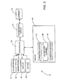
- FIG 3 schematically illustrates the main components of each of the mobile telephones 3 shown in Figure 1 .
- the mobile telephones 3 include a transceiver circuit 71 that is operable to transmit signals to and to receive signals from the base station 5 via one or more antenna 73.
- the mobile telephone 3 also includes a controller 75 which controls the operation of the mobile telephone 3 and which is connected to the transceiver circuit 71 and to a loudspeaker 77, a microphone 79, a display 81, and a keypad 83.
- the controller 75 operates in accordance with software instructions stored within memory 85. As shown, these software instructions include, among other things, an operating system 87. In this embodiment, the memory also provides uplink data buffers 89.
- the software for controlling the handover process is provided by a handover module 91, the operation of which will be described below.
- both the base station 5 and the mobile telephones 3 are described, for ease of understanding, as having respective discrete handover modules which control the handover procedure when a mobile telephone 3 moves from a source base station to a target base station.
- the features may be provided in this way for certain applications, for example where an existing system has been modified to implement the invention, in other applications, for example in systems designed with the inventive features in mind from the outset, the handover features may be built into the overall operating system or code and so a handover module as a discrete entity may not be discernible. This is similarly true for the other software modules.
- the mobile telephone 3 that is changing base stations 5 will be referred to as a UE
- the source base station 5-1 will be referred to as the source eNodeB
- the target base station 5-2 will be referred to as the target eNodeB.
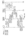
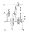
- Figures 4A and 4B illustrate the currently agreed signalling flow for the control plane for the inter eNodeB handover (HO) procedure. As shown, the sequence proceeds as follows:
- the handover execution phase begins in the UE on receiving the RRC Handover Command in step 4 form the source eNodeB.
- the UE stops the uplink transmission, starts buffering the uplink packets, detaches from the old cell and attempts synchronisation to the target cell in Step 5.
- the target eNodeB After the UE attains uplink synchronisation, the target eNodeB responds with an uplink allocation for sending a Handover Complete message.
- the UE sends the Handover Complete Message in Step 6 which completes the HO procedure in the UE.
- the target eNodeB After the reception of the Handover Complete Message in the target eNodeB, it makes an appropriate allocation of the resources for the downlink U-plane data, based on the status of downlink buffers and the QoS parameters received from the source eNodeB (which identify the service that was being provided to the UE by the source eNodeB).
- the target eNodeB has to allocate uplink U-plane resources for the UE. It could do this based on a guess of the uplink buffer status within the UE and the QoS parameters.
- uplink U-plane resource allocations within the target cell immediately after handover would be suboptimal considering that the UE was unable to perform any UL transmissions while it was trying to synchronize with the target cell.
- the UE During the time that the UE can not transmit uplink data, it buffers the data in its internal buffers 89. By the time that the UE is able to send uplink data to the target eNodeB, there may be a large number of uplink data packets sitting in the uplink buffers 89. In order that the UE can quickly bring its buffers levels down, the target eNodeB must allocate sufficient resources in the target cell for this unlink U-plane data.
- the target eNodeB may make an initial allocation to the UE based on the last buffer status report sent by the UE to the source eNodeB and the QoS parameters.
- the UE can subsequently request additional uplink resources by sending an uplink buffer Status report to bring down the increased buffer levels due to the pause in the uplink transmission.
- this requires the source eNodeB to have to store the most recent uplink buffer status report for each UE and transfer it to the target eNodeB during the handover procedure.
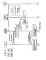
- the handover procedure described above is modified slightly such that when the UE sends the HANDOVER COMPLETE message, it appends to that message the latest uplink buffer status report.
- the target eNodeB can then use this information to allocate accurately the required uplink resources that are needed by the UE.
- This modified handover procedure is illustrated in Figures 5A and 5B and has a number of advantages over the other techniques discussed above:
- the handover techniques described in the present application can be employed in any communications system.
- many of these handover techniques can be used in wire or wireless based communications systems which either use electromagnetic signals or acoustic signals to carry the data.
- the base stations and the mobile telephones can be considered as communications nodes or devices which communicate with each other.
- the source and target communications nodes will be formed by respective scheduling entities within one base station.
- Other communications nodes or devices may include user devices such as, for example, personal digital assistants, laptop computers, web browsers, etc.
- the software modules may be provided in compiled or un-compiled form and may be supplied to the base station or to the mobile telephone as a signal over a computer network, or on a recording medium. Further, the functionality performed by part or all of this software may be performed using one or more dedicated hardware circuits. However, the use of software modules is preferred as it facilitates the updating of base station 5 and the mobile telephones 3 in order to update their functionalities.
- LTE Long Term Evolution (of UTRAN) eNodeB - E-UTRAN Node B UE - User Equipment- mobile communication device DL - downlink - link from base to mobile UL - uplink - link from mobile to base MME - Mobility Management Entity UPE- User Plane Entity HO - Handover RLC - Radio Link Control RRC - Radio Resource Control RRM - Radio Resource Management SAE - System Architecture Evolution C-RNTI - Cell-Radio Network Temporary Identifier SIB - System Information Block U-plane - User Plane X2 Interface - Interface between two eNodeB
- the signalling sequence for the intra-LTE handover procedure has been captured in TS 36.300, however the specifics on resource allocations in the target cell have not yet been addressed in detail. In this contribution we address some further details on the UL resource allocation in the target cell after Handover and handling of UL buffer status report.
- the handover procedure consist of the following: radio conditions are changing, UE sends a measurement report, the network takes a decision and prepares the target cell, the network commands the UE to change cell, the UE reconfigures L1 and synchronizes to the target cell, data is transmitted and received in the target cell and resources in the source cell are released.
- the handover execution phase begins in the UE on receiving the RRC Handover Command in step 4 form the source eNodeB.
- the UE On receiving the Handover Command the UE shall stop the UL transmission, start buffering the UL packets, detach from the old cell and shall attempt to synchronisation to target cell in Step 5.
- eNodeB After the UE attains UL synchronisation, eNodeB will respond with UL allocation for sending Handover Complete message. The UE shall send the Handover Complete Message in Step 6 which will complete the HO procedure in UE.
- the target eNodeB After the reception of Handover Complete Message in the target eNodeB, it shall appropriately allocate the resources for DL-U plane data based on the status of DL buffers and the QoS parameters received from source eNodeB. However for the UL-U plane data, the target eNodeB could allocate resources based on a guess of the buffer status in the UL within UE and the QoS parameters. Such UL- U plane resource allocations within the target cell immediately after HO would be suboptimal considering the fact that the UE was unable to perform any UL transmissions while it was trying to synchronize with the target cell. This can cause large amount of UL data packets to be buffered within the UE during the Hand over execution phase and the buffers levels need to be quickly brought down by allocating the sufficient amount of resources for UL- U plane data in the target cell.
- Step 1 Initially UL Resources are allocated in the target cell based on the last buffer status report sent by the UE in the source cell and the QoS parameters.
- Step 2 UE shall subsequently request additional UL resources subsequently by sending UL buffer Status report to bring down the increased buffer levels due to pause in UL transmission.
- Step 1 UE sends the UL buffer status report along with the Handover Complete Message and the eNB allocates the UL resources accordingly.
- the UE stops the UL transmissions and attempts to synchronize with the target cell.
- the buffers in the UE would keep accumulating the data packets till the UE receives the UL grants after the HO in the target cell. It is necessary that the Network accurately allocates the UL resources in the target cell such that increased buffer levels due to the pause in UL transmission are brought down quickly.
- the UL Buffer Status Report is transmitted by the UE along with the Hand over Complete Message. This would eliminate the need for the storing the most recent UL Buffer status report and transferring it to the target ceII/eNodeB MAC entity during handovers.
Landscapes
- Engineering & Computer Science (AREA)
- Computer Networks & Wireless Communication (AREA)
- Signal Processing (AREA)
- Mobile Radio Communication Systems (AREA)
Priority Applications (4)
| Application Number | Priority Date | Filing Date | Title |
|---|---|---|---|
| EP21154134.7A EP3849240B1 (de) | 2007-02-05 | 2008-01-30 | Ressourcenzuordnung in zielzellen nach dem handover |
| EP16201276.9A EP3166357B1 (de) | 2007-02-05 | 2008-01-30 | Ressourcenzuordnung in zielzellen nach dem handover |
| EP15154233.9A EP2916588B1 (de) | 2007-02-05 | 2008-01-30 | Ressourcenzuordnung in Zielzellen nach einer Weiterleitung |
| EP18174441.8A EP3393171B1 (de) | 2007-02-05 | 2008-01-30 | Ressourcenzuordnung in zielzellen nach dem handover |
Applications Claiming Priority (2)
| Application Number | Priority Date | Filing Date | Title |
|---|---|---|---|
| GBGB0702169.4A GB0702169D0 (en) | 2007-02-05 | 2007-02-05 | Resource Allocation |
| EP08710821.3A EP2119145B1 (de) | 2007-02-05 | 2008-01-30 | Ressourcenzuordnung in zielmobilgeräten nach einer weiterleitung |
Related Parent Applications (1)
| Application Number | Title | Priority Date | Filing Date |
|---|---|---|---|
| EP08710821.3 Division | 2008-01-30 |
Related Child Applications (4)
| Application Number | Title | Priority Date | Filing Date |
|---|---|---|---|
| EP15154233.9A Division EP2916588B1 (de) | 2007-02-05 | 2008-01-30 | Ressourcenzuordnung in Zielzellen nach einer Weiterleitung |
| EP16201276.9A Division EP3166357B1 (de) | 2007-02-05 | 2008-01-30 | Ressourcenzuordnung in zielzellen nach dem handover |
| EP21154134.7A Division EP3849240B1 (de) | 2007-02-05 | 2008-01-30 | Ressourcenzuordnung in zielzellen nach dem handover |
| EP18174441.8A Division EP3393171B1 (de) | 2007-02-05 | 2008-01-30 | Ressourcenzuordnung in zielzellen nach dem handover |
Publications (2)
| Publication Number | Publication Date |
|---|---|
| EP2528288A2 true EP2528288A2 (de) | 2012-11-28 |
| EP2528288A3 EP2528288A3 (de) | 2013-02-20 |
Family
ID=37891308
Family Applications (7)
| Application Number | Title | Priority Date | Filing Date |
|---|---|---|---|
| EP16201276.9A Active EP3166357B1 (de) | 2007-02-05 | 2008-01-30 | Ressourcenzuordnung in zielzellen nach dem handover |
| EP12175021.0A Active EP2512079B1 (de) | 2007-02-05 | 2008-01-30 | Ressourcenzuordnung in zielmobilgeräten nach einer weiterleitung |
| EP12178535A Withdrawn EP2528288A3 (de) | 2007-02-05 | 2008-01-30 | Ressourcenzuordnung in Zielmobilgeräten Nach Einer Weiterleitung |
| EP18174441.8A Not-in-force EP3393171B1 (de) | 2007-02-05 | 2008-01-30 | Ressourcenzuordnung in zielzellen nach dem handover |
| EP15154233.9A Active EP2916588B1 (de) | 2007-02-05 | 2008-01-30 | Ressourcenzuordnung in Zielzellen nach einer Weiterleitung |
| EP08710821.3A Active EP2119145B1 (de) | 2007-02-05 | 2008-01-30 | Ressourcenzuordnung in zielmobilgeräten nach einer weiterleitung |
| EP21154134.7A Active EP3849240B1 (de) | 2007-02-05 | 2008-01-30 | Ressourcenzuordnung in zielzellen nach dem handover |
Family Applications Before (2)
| Application Number | Title | Priority Date | Filing Date |
|---|---|---|---|
| EP16201276.9A Active EP3166357B1 (de) | 2007-02-05 | 2008-01-30 | Ressourcenzuordnung in zielzellen nach dem handover |
| EP12175021.0A Active EP2512079B1 (de) | 2007-02-05 | 2008-01-30 | Ressourcenzuordnung in zielmobilgeräten nach einer weiterleitung |
Family Applications After (4)
| Application Number | Title | Priority Date | Filing Date |
|---|---|---|---|
| EP18174441.8A Not-in-force EP3393171B1 (de) | 2007-02-05 | 2008-01-30 | Ressourcenzuordnung in zielzellen nach dem handover |
| EP15154233.9A Active EP2916588B1 (de) | 2007-02-05 | 2008-01-30 | Ressourcenzuordnung in Zielzellen nach einer Weiterleitung |
| EP08710821.3A Active EP2119145B1 (de) | 2007-02-05 | 2008-01-30 | Ressourcenzuordnung in zielmobilgeräten nach einer weiterleitung |
| EP21154134.7A Active EP3849240B1 (de) | 2007-02-05 | 2008-01-30 | Ressourcenzuordnung in zielzellen nach dem handover |
Country Status (8)
| Country | Link |
|---|---|
| US (2) | US9282493B2 (de) |
| EP (7) | EP3166357B1 (de) |
| JP (7) | JP4962747B2 (de) |
| KR (2) | KR101244011B1 (de) |
| CN (4) | CN105142192B (de) |
| ES (4) | ES2428162T3 (de) |
| GB (1) | GB0702169D0 (de) |
| WO (1) | WO2008099719A1 (de) |
Families Citing this family (35)
| Publication number | Priority date | Publication date | Assignee | Title |
|---|---|---|---|---|
| WO2010073700A1 (ja) * | 2008-12-26 | 2010-07-01 | 日本電気株式会社 | 無線通信システム、通信制御方法、無線基地局、無線端末および記憶媒体 |
| WO2010085913A1 (zh) * | 2009-02-02 | 2010-08-05 | 华为技术有限公司 | 一种多载波小区切换方法、装置和系统 |
| US8489098B2 (en) * | 2009-02-13 | 2013-07-16 | Telefonaktiebolaget Lm Ericsson (Publ) | Method and arrangement for real-time difference determination for mobile terminal positioning |
| KR101562224B1 (ko) * | 2009-04-23 | 2015-10-22 | 삼성전자주식회사 | 무선통신 시스템에서 핸드오버 단절 시간을 감소시키기 위한 데이터 포워딩 장치 및 방법 |
| WO2011020229A1 (zh) * | 2009-08-17 | 2011-02-24 | 上海贝尔股份有限公司 | 在中继链路上处理数据的方法和相关设备 |
| WO2011052774A1 (ja) | 2009-11-02 | 2011-05-05 | 京セラ株式会社 | 無線通信システム、低電力基地局、高電力基地局、無線端末、及び無線通信方法 |
| US8594657B2 (en) * | 2010-06-15 | 2013-11-26 | Htc Corporation | Method for reporting MDT log and mobile communication device utilizing the same |
| EP2437547A3 (de) * | 2010-09-30 | 2013-12-04 | Samsung Electronics Co., Ltd. | Vorrichtung und Verfahren zur Durchführung einer Übergabe zwischen heterogenen Funknetzwerken |
| GB2488512B (en) | 2011-01-28 | 2015-03-11 | Sca Ipla Holdings Inc | Telecommunications method and system |
| CN103460752A (zh) * | 2011-04-06 | 2013-12-18 | 瑞典爱立信有限公司 | 用于管理用户设备的切换的方法 |
| US20130044731A1 (en) * | 2011-08-15 | 2013-02-21 | Qualcomm Incorporated | Proactive Feedback Transmissions During Handover Procedures |
| GB2494108A (en) * | 2011-08-22 | 2013-03-06 | Samsung Electronics Co Ltd | Determining trigger events for sending measurement reports in a cellular wireless communication network |
| GB2494107B (en) | 2011-08-22 | 2017-03-29 | Samsung Electronics Co Ltd | Wireless communication |
| US20130107859A1 (en) * | 2011-10-27 | 2013-05-02 | Qualcomm Incorporated | AVOIDING VOICE OVER INTERNET PROTOCOL (VoIP) PACKET LOSS DUE TO INTER-RADIO ACCESS TECHNOLOGY (RAT) HANDOVER |
| CN103139918B (zh) | 2011-11-30 | 2016-05-18 | 华为技术有限公司 | 一种实现数据调度的方法、装置和系统 |
| KR102121526B1 (ko) * | 2012-07-23 | 2020-06-10 | 삼성전자주식회사 | 클라우드 셀 통신 시스템에서 데이터 스케쥴링 장치 및 방법 |
| CN103997762B (zh) * | 2013-02-19 | 2017-08-25 | 中兴通讯股份有限公司 | 一种小区切换方法及系统 |
| EP2836018A1 (de) * | 2013-08-09 | 2015-02-11 | Alcatel Lucent | Verkehrslenkung durch ein zelluläres Funkzugangsnetz (RAN) in einem Netzwerk, das Access Network Discovery and Selection Function (ANDSF) unterstützt |
| US9313698B2 (en) * | 2013-10-11 | 2016-04-12 | Blackberry Limited | Method and apparatus for handover in heterogeneous cellular networks |
| US9554397B2 (en) * | 2014-05-05 | 2017-01-24 | Blackberry Limited | Identifying a subframe containing information relating to an uplink grant |
| CN105940722B (zh) * | 2014-08-27 | 2019-11-05 | 华为技术有限公司 | 一种ac、sta、ap及控制方法 |
| CN112954652B (zh) * | 2014-10-17 | 2024-06-25 | 三星电子株式会社 | 用于处理设备到设备(d2d)通信的方法和系统 |
| KR102253258B1 (ko) * | 2015-03-31 | 2021-05-21 | 삼성전자주식회사 | 플렉서블 듀플렉스 시스템에서 셀 간 간섭 측정 방법 및 장치 |
| EP3293940B1 (de) * | 2015-05-27 | 2019-04-24 | Huawei Technologies Co., Ltd. | Verfahren und vorrichtung zur benutzergeräteumschaltung |
| CN106792927B (zh) * | 2015-11-23 | 2021-06-25 | 中兴通讯股份有限公司 | 一种上行业务识别切换方法及装置、基站 |
| WO2017126246A1 (ja) * | 2016-01-21 | 2017-07-27 | パナソニック インテレクチュアル プロパティ コーポレーション オブ アメリカ | 通信システム、端末及び通信制御方法 |
| KR102419981B1 (ko) * | 2016-02-19 | 2022-07-12 | 삼성전자 주식회사 | 무선 통신 네트워크에서 핸드오버시 데이터 전송 중단 시간을 최소화하는 방법 및 장치 |
| CN107295658B (zh) * | 2016-04-01 | 2019-12-20 | 电信科学技术研究院 | 一种切换过程中的资源分配方法、源基站及目标基站 |
| CN107333257B (zh) * | 2016-04-29 | 2020-06-16 | 展讯通信(上海)有限公司 | 多卡用户设备及其上行数据传输方法 |
| JP6683849B2 (ja) | 2016-06-24 | 2020-04-22 | 華為技術有限公司Huawei Technologies Co.,Ltd. | スケジューリング方法及び基地局 |
| CN107734574B (zh) * | 2016-08-12 | 2020-12-01 | 华为技术有限公司 | 小区间切换的方法和控制器 |
| CN108271267B (zh) * | 2016-12-30 | 2021-07-09 | 中国电信股份有限公司 | 终端资源的分配方法、eNB和VoLTE系统 |
| US10977243B2 (en) | 2018-01-22 | 2021-04-13 | Ensemble Rcm, Llc | Processing of transaction records in a database based on reason codes |
| WO2023133812A1 (en) | 2022-01-14 | 2023-07-20 | Nokia Shanghai Bell Co., Ltd. | Method and apparatus for quality of experience reporting continuity |
| US12543081B2 (en) * | 2023-03-28 | 2026-02-03 | Qualcomm Incorporated | Techniques for configuring an initial uplink transmission after a cell switch |
Family Cites Families (13)
| Publication number | Priority date | Publication date | Assignee | Title |
|---|---|---|---|---|
| FI101763B (fi) * | 1995-12-01 | 1998-08-14 | Nokia Mobile Phones Ltd | Siirrettävän tiedon koostumuksen säilyttäminen tukiaseman vaihdon yhte ydessä |
| FI102654B (fi) * | 1996-02-22 | 1999-01-15 | Nokia Mobile Phones Ltd | Menetelmä tukiaseman vaihtamiseksi ATM-verkon radiolaajennuksessa |
| KR100547793B1 (ko) * | 2001-12-29 | 2006-02-01 | 삼성전자주식회사 | 이동통신시스템에서 역방향 데이터 전송 제어 방법 |
| CN1182672C (zh) * | 2002-01-30 | 2004-12-29 | 华为技术有限公司 | 一种cdma系统中无线资源管理优化的方法 |
| US6717927B2 (en) | 2002-04-05 | 2004-04-06 | Interdigital Technology Corporation | System for efficient recovery of node B buffered data following serving high speed downlink shared channel cell change |
| EP1432262A1 (de) | 2002-12-20 | 2004-06-23 | Matsushita Electric Industrial Co., Ltd. | Protokollkontextbewahrung in Mobilkommunikationssystemen |
| WO2004077871A1 (ja) * | 2003-02-27 | 2004-09-10 | Mitsubishi Denki Kabushiki Kaisha | 基地局、端末、および通信システム |
| EP1509011A3 (de) * | 2003-08-16 | 2011-01-19 | Samsung Electronics Co., Ltd. | Verfahren und Vorrichtung zur Planung für Uplink Paketübertragung in einem mobilen Kommunikationssystem |
| US20060280145A1 (en) * | 2005-06-10 | 2006-12-14 | Revel Agnes M | Event trigger for scheduling information in wireless communication networks |
| EP3565313B1 (de) * | 2005-10-31 | 2020-04-08 | Evolved Wireless LLC | Verfahren zum senden und empfangen von funkzugangsinformationen in einem drahtlosmobilkommunikationssystem |
| AU2006309464B2 (en) * | 2005-10-31 | 2009-10-29 | Lg Electronics Inc. | Method for processing control information in a wireless mobile communication system |
| WO2007052922A1 (en) | 2005-10-31 | 2007-05-10 | Lg Electronics Inc. | Data transfer management in a radio communications network |
| JP4677490B2 (ja) * | 2005-10-31 | 2011-04-27 | エルジー エレクトロニクス インコーポレイティド | 無線移動通信システムにおける無線接続情報送受信方法 |
-
2007
- 2007-02-05 GB GBGB0702169.4A patent/GB0702169D0/en not_active Ceased
-
2008
- 2008-01-30 EP EP16201276.9A patent/EP3166357B1/de active Active
- 2008-01-30 CN CN201510608266.9A patent/CN105142192B/zh not_active Expired - Fee Related
- 2008-01-30 ES ES08710821T patent/ES2428162T3/es active Active
- 2008-01-30 EP EP12175021.0A patent/EP2512079B1/de active Active
- 2008-01-30 ES ES15154233.9T patent/ES2618497T3/es active Active
- 2008-01-30 EP EP12178535A patent/EP2528288A3/de not_active Withdrawn
- 2008-01-30 JP JP2009530724A patent/JP4962747B2/ja not_active Expired - Fee Related
- 2008-01-30 KR KR1020117010736A patent/KR101244011B1/ko active Active
- 2008-01-30 WO PCT/JP2008/051889 patent/WO2008099719A1/en not_active Ceased
- 2008-01-30 KR KR1020097018612A patent/KR101206078B1/ko not_active Expired - Fee Related
- 2008-01-30 EP EP18174441.8A patent/EP3393171B1/de not_active Not-in-force
- 2008-01-30 CN CN201410686922.2A patent/CN104469954B/zh not_active Expired - Fee Related
- 2008-01-30 EP EP15154233.9A patent/EP2916588B1/de active Active
- 2008-01-30 EP EP08710821.3A patent/EP2119145B1/de active Active
- 2008-01-30 ES ES12175021.0T patent/ES2529676T3/es active Active
- 2008-01-30 EP EP21154134.7A patent/EP3849240B1/de active Active
- 2008-01-30 CN CN201210048770.4A patent/CN102625385B/zh active Active
- 2008-01-30 ES ES16201276.9T patent/ES2690988T3/es active Active
- 2008-01-30 CN CN200880004117.XA patent/CN101606419B/zh not_active Expired - Fee Related
- 2008-01-31 US US12/449,306 patent/US9282493B2/en active Active
-
2012
- 2012-03-13 JP JP2012055861A patent/JP5348435B2/ja active Active
-
2013
- 2013-06-25 JP JP2013132285A patent/JP2013232946A/ja active Pending
-
2014
- 2014-03-31 JP JP2014071073A patent/JP5574137B1/ja not_active Expired - Fee Related
- 2014-06-24 JP JP2014129336A patent/JP2014197894A/ja active Pending
-
2015
- 2015-08-27 JP JP2015167630A patent/JP6028952B2/ja not_active Expired - Fee Related
-
2016
- 2016-01-20 US US15/001,546 patent/US9788243B2/en not_active Expired - Fee Related
- 2016-10-19 JP JP2016204907A patent/JP6217948B2/ja active Active
Non-Patent Citations (1)
| Title |
|---|
| None |
Also Published As
Similar Documents
| Publication | Publication Date | Title |
|---|---|---|
| US9788243B2 (en) | Resource allocation in target cell after handover | |
| EP2206382A1 (de) | Betriebsmittelzuteilung | |
| CN101543130B (zh) | 在移动通信系统中进行切换之时选择接入方法 |
Legal Events
| Date | Code | Title | Description |
|---|---|---|---|
| PUAI | Public reference made under article 153(3) epc to a published international application that has entered the european phase |
Free format text: ORIGINAL CODE: 0009012 |
|
| AC | Divisional application: reference to earlier application |
Ref document number: 2119145 Country of ref document: EP Kind code of ref document: P |
|
| AK | Designated contracting states |
Kind code of ref document: A2 Designated state(s): AT BE BG CH CY CZ DE DK EE ES FI FR GB GR HR HU IE IS IT LI LT LU LV MC MT NL NO PL PT RO SE SI SK TR |
|
| PUAL | Search report despatched |
Free format text: ORIGINAL CODE: 0009013 |
|
| AK | Designated contracting states |
Kind code of ref document: A3 Designated state(s): AT BE BG CH CY CZ DE DK EE ES FI FR GB GR HR HU IE IS IT LI LT LU LV MC MT NL NO PL PT RO SE SI SK TR |
|
| RIC1 | Information provided on ipc code assigned before grant |
Ipc: H04W 36/02 20090101AFI20130114BHEP |
|
| 17P | Request for examination filed |
Effective date: 20130812 |
|
| RBV | Designated contracting states (corrected) |
Designated state(s): AT BE BG CH CY CZ DE DK EE ES FI FR GB GR HR HU IE IS IT LI LT LU LV MC MT NL NO PL PT RO SE SI SK TR |
|
| GRAP | Despatch of communication of intention to grant a patent |
Free format text: ORIGINAL CODE: EPIDOSNIGR1 |
|
| RIC1 | Information provided on ipc code assigned before grant |
Ipc: H04W 36/02 20090101AFI20140908BHEP |
|
| INTG | Intention to grant announced |
Effective date: 20141007 |
|
| STAA | Information on the status of an ep patent application or granted ep patent |
Free format text: STATUS: THE APPLICATION IS DEEMED TO BE WITHDRAWN |
|
| 18D | Application deemed to be withdrawn |
Effective date: 20150218 |