EP2528721B1 - Kunststoffspritzwerkzeug und verfahren zum kunststoffspritzen - Google Patents
Kunststoffspritzwerkzeug und verfahren zum kunststoffspritzen Download PDFInfo
- Publication number
- EP2528721B1 EP2528721B1 EP11704554.2A EP11704554A EP2528721B1 EP 2528721 B1 EP2528721 B1 EP 2528721B1 EP 11704554 A EP11704554 A EP 11704554A EP 2528721 B1 EP2528721 B1 EP 2528721B1
- Authority
- EP
- European Patent Office
- Prior art keywords
- nozzle
- hot runner
- nozzle tip
- plastic injection
- coolant
- Prior art date
- Legal status (The legal status is an assumption and is not a legal conclusion. Google has not performed a legal analysis and makes no representation as to the accuracy of the status listed.)
- Not-in-force
Links
- 239000004033 plastic Substances 0.000 title claims description 14
- 229920003023 plastic Polymers 0.000 title claims description 14
- 238000000034 method Methods 0.000 title claims description 9
- 238000002347 injection Methods 0.000 title description 9
- 239000007924 injection Substances 0.000 title description 9
- 238000001816 cooling Methods 0.000 claims description 15
- 239000002826 coolant Substances 0.000 claims description 10
- 238000001746 injection moulding Methods 0.000 claims description 6
- 238000010438 heat treatment Methods 0.000 claims description 5
- 239000003507 refrigerant Substances 0.000 description 5
- 239000007788 liquid Substances 0.000 description 3
- 230000000694 effects Effects 0.000 description 1
- 238000007710 freezing Methods 0.000 description 1
- 230000008014 freezing Effects 0.000 description 1
- 238000002955 isolation Methods 0.000 description 1
- 238000012986 modification Methods 0.000 description 1
- 230000004048 modification Effects 0.000 description 1
- 230000003716 rejuvenation Effects 0.000 description 1
- 238000000926 separation method Methods 0.000 description 1
- 230000008016 vaporization Effects 0.000 description 1
Images



Classifications
-
- B—PERFORMING OPERATIONS; TRANSPORTING
- B29—WORKING OF PLASTICS; WORKING OF SUBSTANCES IN A PLASTIC STATE IN GENERAL
- B29C—SHAPING OR JOINING OF PLASTICS; SHAPING OF MATERIAL IN A PLASTIC STATE, NOT OTHERWISE PROVIDED FOR; AFTER-TREATMENT OF THE SHAPED PRODUCTS, e.g. REPAIRING
- B29C45/00—Injection moulding, i.e. forcing the required volume of moulding material through a nozzle into a closed mould; Apparatus therefor
- B29C45/17—Component parts, details or accessories; Auxiliary operations
- B29C45/26—Moulds
- B29C45/27—Sprue channels ; Runner channels or runner nozzles
- B29C45/2737—Heating or cooling means therefor
-
- B—PERFORMING OPERATIONS; TRANSPORTING
- B29—WORKING OF PLASTICS; WORKING OF SUBSTANCES IN A PLASTIC STATE IN GENERAL
- B29C—SHAPING OR JOINING OF PLASTICS; SHAPING OF MATERIAL IN A PLASTIC STATE, NOT OTHERWISE PROVIDED FOR; AFTER-TREATMENT OF THE SHAPED PRODUCTS, e.g. REPAIRING
- B29C45/00—Injection moulding, i.e. forcing the required volume of moulding material through a nozzle into a closed mould; Apparatus therefor
- B29C45/17—Component parts, details or accessories; Auxiliary operations
- B29C45/26—Moulds
- B29C45/27—Sprue channels ; Runner channels or runner nozzles
- B29C45/2737—Heating or cooling means therefor
- B29C2045/2753—Heating means and cooling means, e.g. heating the runner nozzle and cooling the nozzle tip
-
- B—PERFORMING OPERATIONS; TRANSPORTING
- B29—WORKING OF PLASTICS; WORKING OF SUBSTANCES IN A PLASTIC STATE IN GENERAL
- B29C—SHAPING OR JOINING OF PLASTICS; SHAPING OF MATERIAL IN A PLASTIC STATE, NOT OTHERWISE PROVIDED FOR; AFTER-TREATMENT OF THE SHAPED PRODUCTS, e.g. REPAIRING
- B29C45/00—Injection moulding, i.e. forcing the required volume of moulding material through a nozzle into a closed mould; Apparatus therefor
- B29C45/17—Component parts, details or accessories; Auxiliary operations
- B29C45/26—Moulds
- B29C45/27—Sprue channels ; Runner channels or runner nozzles
- B29C45/278—Nozzle tips
-
- B—PERFORMING OPERATIONS; TRANSPORTING
- B29—WORKING OF PLASTICS; WORKING OF SUBSTANCES IN A PLASTIC STATE IN GENERAL
- B29C—SHAPING OR JOINING OF PLASTICS; SHAPING OF MATERIAL IN A PLASTIC STATE, NOT OTHERWISE PROVIDED FOR; AFTER-TREATMENT OF THE SHAPED PRODUCTS, e.g. REPAIRING
- B29C45/00—Injection moulding, i.e. forcing the required volume of moulding material through a nozzle into a closed mould; Apparatus therefor
- B29C45/17—Component parts, details or accessories; Auxiliary operations
- B29C45/26—Moulds
- B29C45/27—Sprue channels ; Runner channels or runner nozzles
- B29C45/28—Closure devices therefor
- B29C45/2806—Closure devices therefor consisting of needle valve systems
-
- B—PERFORMING OPERATIONS; TRANSPORTING
- B29—WORKING OF PLASTICS; WORKING OF SUBSTANCES IN A PLASTIC STATE IN GENERAL
- B29C—SHAPING OR JOINING OF PLASTICS; SHAPING OF MATERIAL IN A PLASTIC STATE, NOT OTHERWISE PROVIDED FOR; AFTER-TREATMENT OF THE SHAPED PRODUCTS, e.g. REPAIRING
- B29C45/00—Injection moulding, i.e. forcing the required volume of moulding material through a nozzle into a closed mould; Apparatus therefor
- B29C45/17—Component parts, details or accessories; Auxiliary operations
- B29C45/26—Moulds
- B29C45/27—Sprue channels ; Runner channels or runner nozzles
- B29C45/30—Flow control means disposed within the sprue channel, e.g. "torpedo" construction
Definitions
- the invention initially relates to a plastic injection tool according to the features of the preamble of claim 1.
- the invention relates to a method for carrying out a plastic injection method according to the features of the preamble of claim 4.
- plastic injection molding tools or methods for plastic injection have already become known in various embodiments. It is for example on the DE19956215C2 . DE29609356U1 . DE202008006865U1 and the DE102004033469B3 directed. With regard to cooling as such is also on the DE102005058963A1 and the DE102008000452A1 directed.
- At one of the US 4,438,064 known plastic injection tool exits coolant through radial opening in an outer coaxial line.
- the outlet is in front of the closure area of the nozzle tip.
- the invention is concerned with the task of specifying a plastic injection mold with an advantageously cooled hot runner nozzle. Moreover, with the object of specifying a method for carrying out a plastic injection method by means of such a hot runner nozzle.
- the cooling takes place by means of a refrigerant conducted into the tip, wherein a supply and discharge for the refrigerant is provided. It may be concentrically arranged tubes.
- an internally heated hot runner nozzle may be provided for this purpose, for example, that a heating torpedo provided for this purpose, which is usually centrally located in the hot runner nozzle, for example, in cross-section circular ring and corresponding supply lines leaves, in which, even with a certain isolation optionally, the coolant can be supplied and discharged.
- the required throttle point or at least the outlet of the coolant, preferably liquid, from the supply line is formed directly in the nozzle tip.
- a nozzle tip is in the context of the application in particular the one Designated area of the hot runner nozzle, which extends on the outside with the closure angle resulting taper. This rejuvenation is cone-like.
- the said conical tip itself, or the said area of the closure needle or the area surrounding the outlet opening in the conical tip, such as outside heated hot runner nozzle, is cooled so that virtually no visible surface difference in the gate area of the severed workpiece the surrounding areas can determine more.
- the cooling can be carried out in particular at the end of a plastic injection cycle. Beginning shortly before demolding and, for example, until the actual separation of the tool halves. Such intermittent cooling provides the cooling performance, especially when it is required to produce the desired high surface quality in the gate area.
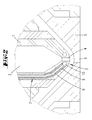
- a conventional externally heated hot runner nozzle 1 which has a central Masse press Arthursweg 2 and a nozzle tip 3 with an outlet channel 4 in the insert part 5, the connection path 6 is formed to the tool cavity.
- a coaxially guided coolant line 7 which has an inner supply line 8 and an outer discharge line 9
- first liquid refrigerant is passed through the supply line 8 in the region of the nozzle tip 3, there emerges in a bore 10, whereby a relaxation effect and thus a cooling occurs.
- the bore 10 is formed here annularly to the exit path 4. However, it can also be formed, in addition or alone, in the mass passage direction, to a rearward region of the nozzle tip 3.
- the return line 9 may be provided coaxially as shown here, but it may also be formed locally offset from the supply line 8.
- a cooling in one of the nozzle tip outer area as basically in the DE202008006865U1 described, be provided.
- the region of the bore 10 may also be formed, for example, by an inserted Peltier element, and instead of the inlet and outlet lines 8, 9, corresponding electrical cable connections may be provided to act on the Peltier element.
- This embodiment is not according to the invention.
- use can advantageously be made of the fact that the Peltier element in the same way as it cools on one side, emits heat on the other side.
- the entire nozzle tip may be formed, for example, as a Peltier element.
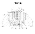
- FIG. 3 is a schematic cross-sectional view of an internally heated hot runner nozzle shown. Inside the nozzle body 1, a Banktorpedo 11 is arranged. The mass path 12 is formed here surrounding the hot runner nozzle 1 and the mass is brought together in the region of the hot runner nozzle tip 3.
- Fig. 4 In reference to Fig. 4 is shown schematically that here according to the invention by a circular shape in cross section heating cartridge 11 required for the supply and discharge of the coolant and basically already described inlets and outlets 8, 9 can be performed and the relevant bore 10 then in the nozzle tip can be trained. Again, there is the necessary relaxation by the exit of the liquid coolant from the very thin line held. 9
- a hot runner nozzle 1 not shown according to the invention in cross-section, in which centrally inside a valve needle 13 is arranged.
- supply and discharge 8, 9 for a refrigerant are also provided in this embodiment, and a recess or cavity 10, which thus enables a vaporizing refrigerant corresponding cooling of the tip 14 of the valve needle 13.
- the supply and discharge lines can always be kept very thin. Their diameters can move in the millimeter, tenths of a millimeter or even micrometer range.
- the lines also need not be concentric but can also be formed side by side. In this case, the supply line may have a smaller diameter than the derivative, for example.
- These lines can be formed by means of lasers in the objects.
- a cooling of the nozzle tip, especially also the said needle tip is carried out, for example, to a temperature of 50 degrees or less, up to 0 degrees or a few degrees of freezing, approximately to minus 5 degrees.
- the disclosure also includes all intermediate values, in particular in 0.5 degree increments, on the one hand to delimit the named area from below and / or above on the other hand, but also to reveal individual values from the named area.
- a part ejected from the mold has a wall temperature of 40 degrees or less. In any case, it is desirable that the injection-molded part also has this temperature approximately in the area of the sprue.
Landscapes
- Engineering & Computer Science (AREA)
- Manufacturing & Machinery (AREA)
- Mechanical Engineering (AREA)
- Moulds For Moulding Plastics Or The Like (AREA)
Description
- Die Erfindung betrifft zunächst ein Kunststoffspritzwerkzeug nach den Merkmalen des Oberbegriffs des Anspruches 1.
- Weiter betrifft die Erfindung ein Verfahren zur Durchführung eines Kunststoffspritzverfahrens nach den Merkmalen des Oberbegriffes des Anspruches 4.
- Derartige Kunststoffspritzwerkzeuge bzw. Verfahren zum Kunststoffspritzen sind bereits in verschiedenen Ausgestaltungen bekannt geworden. Es wird beispielsweise auf die
DE19956215C2 ,DE29609356U1 ,DE202008006865U1 und dieDE102004033469B3 verwiesen. Im Hinblick auf eine Kühlung als solche wird auch auf dieDE102005058963A1 und dieDE102008000452A1 verwiesen. - Bei einem aus der
US 4,438,064 bekannten Kunststoffspritzwerkzeug tritt Kühlmittel durch radiale Öffnung in eine äußere koaxiale Leitung aus. Der Austritt ist vor dem Verschlussbereich der Düsenspitze. - Zum Stand der Technik ist auch auf die
DE 10 2008 018 351 B4 zu verweisen. Hieraus ist eine gekühlte Verschlussnadel bekannt. Darüber hinaus ist auf dieDE 195 35 717 A1 zu verweisen. Hieraus ist eine Heißkanaldüse als solche bekannt. Darüber hinaus ist auf dieUS 5,118,280 A zu verweisen. - Ausgehend von dem Stand der Technik gemäß
US 4,438,064 beschäftigt sich die Erfindung mit der Aufgabe, ein Kunststoffspritzwerkzeug mit einer vorteilhaft gekühlten Heißkanaldüse anzugeben. Darüber hinaus mit der Aufgabe, ein Verfahren zur Durchführung eines Kunststoffspritzverfahrens mittels einer solchen Heißkanaldüse anzugeben. - Diese Aufgabe ist hinsichtlich des Kunststoffspritzwerkzeugs durch den Gegenstand des Anspruches 1 gelöst, wobei darauf abgestellt ist, dass ein Austritt des Kühlmittels in eine Ringleitung unmittelbar in der Düsenspitze, die außenseitig eine kegelförmige, einen Verschlusswinkel ergebende Verjüngung aufweist, gegeben ist.
- Hinsichtlich des Verfahrens ist darauf abgestellt, dass die Kühlung nur zeitlich abschnittsweise durchgeführt wird.
- Es ist bevorzugt, dass die Kühlung mittels eines in die Spitze geleiteten Kältemittels erfolgt, wobei eine Zu- und Ableitung für das Kältemittel vorgesehen ist. Es können sich um konzentrisch angeordnete Rohre handeln.
- Im Falle einer innen beheizten Heißkanaldüse kann zu diesem Zweck beispielsweise vorgesehen sein, dass ein hierfür vorgesehenes Heiztorpedo, welches in der Regel zentral in der Heißkanaldüse angeordnet ist, beispielsweise im Querschnitt kreisringförmig gebildet ist und entsprechend Zuleitungswege belässt, in welchen, auch unter einer gewissen Isolierung gegebenenfalls, das Kühlmittel zugeleitet und abgeleitet werden kann. Insbesondere ist vorgesehen, dass die erforderliche Drosselstelle oder jedenfalls der Austritt des Kühlmittels, bevorzugt flüssig, aus der Zuleitung, unmittelbar in der Düsenspitze ausgebildet ist. Als Düsenspitze ist im Rahmen der Anmeldung insbesondere derjenige Bereich der Heißkanaldüse bezeichnet, der sich außenseitig mit der den Verschlusswinkel ergebenden Verjüngung erstreckt. Diese Verjüngung ist kegelartig. Insbesondere ist angestrebt, dass die genannte Kegelspitze selbst, bzw. der genannte Bereich der Verschlussnadel oder der Bereich umgebend zur Austrittsöffnung in der Kegelspitze, etwa bei außen beheizter Heißkanaldüse, so gekühlt wird, dass sich in dem Angussbereich des abgetrennten Werkstückes praktisch keine sichtbare Oberflächenunterschiedlichkeit zu den umgebenden Bereichen mehr feststellen lassen kann.
- Zeitlich kann die Kühlung insbesondere zum Ende eines Kunststoffspritzzyklus durchgeführt werden. Beginnend kurz vor dem Entformen und zeitlich beispielsweise bis zum tatsächlichen Trennen der Werkzeughälften. Eine solche intermittierende Kühlung erbringt die Kühlleistung insbesondere dann, wenn Sie zur Erzeugung der gewünschten hohen Oberflächenqualität im Bereich des Angusses erforderlich ist.
- Nachstehend ist die Erfindung des Weiteren anhand der beigefügten Zeichnung, die jedoch lediglich Ausführungsbeispiele darstellt, erläutert. Hierbei zeigt:
- Fig. 1
- eine schematische Querschnittsdarstellung einer Heißkanaldüse mit Außenbeheizung nicht gemäß der Erfindung;
- Fig. 2
- eine Ausschnittsvergrößerung aus
Fig. 1 betreffend die Düsenspitze nicht gemäß der Erfindung; - Fig. 3
- eine schematische Querschnittsansicht einer Heißkanaldüse mit Innenbeheizung;
- Fig. 4
- eine Vergrößerung des Düsenspitzenbereiches der Darstellung gemäß
Fig. 3 ; - Fig. 5
- eine schematische Querschnittsdarstellung einer Heißkanaldüse mit Verschlussnadel nicht gemäß der Erfindung, im Verschlusszustand.
- Mit Bezug zunächst zu
Fig. 1 ist eine übliche außen beheizte Heißkanaldüse 1 dargestellt, die einen zentralen Massedurchleitungsweg 2 aufweist und eine Düsenspitze 3 mit einem Austrittskanal 4 in dem Einsatzteil 5 ist der Verbindungsweg 6 zum Werkzeughohlraum ausgebildet. - Mit Bezug zu
Fig. 2 ist zu erkennen, dass mittels einer koaxial geführten Kühlmittelleitung 7, die über eine innere Zuleitung 8 und eine äußere Ableitung 9 verfügt, zunächst flüssiges Kältemittel durch die Zuleitung 8 in den Bereich der Düsenspitze 3 geleitet wird, tritt dort in eine Bohrung 10 aus, wodurch ein Entspannungseffekt und damit eine Kühlung eintritt. Die Bohrung 10 ist hier kreisringförmig zu dem Austrittsweg 4 gebildet. Sie kann aber auch zusätzlich oder allein, in Massedurchtrittsrichtung gesehen, zu einem rückwärtigeren Bereich der Düsenspitze 3 ausgebildet sein. Die Rückleitung 9 kann wie hier dargestellt koaxial vorgesehen sein, sie kann aber auch örtlich versetzt zu der Zuleitung 8 ausgebildet sein. - Ergänzend kann auch eine Kühlung in einem der Düsenspitze äußeren Bereich, wie grundsätzlich in der
DE202008006865U1 beschrieben, vorgesehen sein. - In Abwandlung der Ausführungsform der
Fig. 2 kann der Bereich der Bohrung 10 auch beispielsweise durch ein eingelegtes Peltier-Element gebildet sein und anstatt der Zu- und Ableitung 8, 9 können entsprechende elektrische Kabelverbindungen zur Beaufschlagung des Peltier-Elementes vorgesehen sein. - Diese Ausführung ist nicht gemäß der Erfindung. Hierbei kann vorteilhaft auch davon Gebrauch gemacht werden, dass das Peltier-Element in gleicher Weise wie es auf einer Seite kühlt, auf der anderen Seite Wärme abgibt. Darüber hinaus kann auch die gesamte Düsenspitze beispielsweise als Peltier-Element ausgebildet sein.
- Mit Bezug zu
Fig. 3 ist eine schematische Querschnittsansicht einer innen beheizten Heißkanaldüse dargestellt. Im Inneren des Düsenkörpers 1 ist ein Heiztorpedo 11 angeordnet. Der Masseweg 12 ist hier umgebend zu der Heißkanaldüse 1 ausgebildet und die Masse wird im Bereich der Heißkanaldüsenspitze 3 zusammengeführt. - Mit Bezug zu
Fig. 4 ist schematisch dargestellt, dass hier gemäß der Erfindung durch eine kreisringförmig im Querschnitt gestaltete Heizpatrone 11 die für die Zu- und Ableitung des Kühlmittels erforderlichen und grundsätzlich schon beschriebenen Zu- und Ableitungen 8, 9 durchgeführt werden können und die diesbezügliche Bohrung 10 dann in der Düsenspitze ausgebildet sein kann. Auch hier ergibt sich die notwendige Entspannung durch den Austritt des flüssigen Kühlmittels aus der sehr dünn gehaltenen Zuleitung 9. - Mit Bezug zu
Fig. 5 ist eine Heißkanaldüse 1 nich gemäß der Erfindung im Querschnitt dargestellt, in welcher zentral innen eine Verschlussnadel 13 angeordnet ist. Innerhalb der Verschlussnadel 13 sind auch bei dieser Ausführungsform Zu- und Ableitung 8, 9 für ein Kältemittel vorgesehen und eine Ausnehmung oder Höhlung 10, die ein verdampfendes Kältemittel somit entsprechende Kühlung der Spitze 14 der Verschlussnadel 13 ermöglicht. - Die Zu- und Ableitungen können grundsätzlich sehr dünn gehalten sein. Ihre Durchmesser können sich im Millimeter, zehntel Millimeter oder gar Mikrometer Bereich bewegen. Die Leitungen brauchen auch nicht konzentrisch zu sein sondern können auch nebeneinander ausgebildet sein. Hierbei kann die Zuleitung einen geringern Durchmesser aufweisen als die Ableitung beispielsweise. Diese Leitungen können etwa mittels Laser in den Gegenständen ausgebildet sein.
- Hinsichtlich der Temperaturen ist bevorzugt, dass eine Abkühlung der Düsenspitze, speziell auch der genannten Nadelspitze, bis beispielsweise auf eine Temperatur von 50 Grad oder weniger, bis hin zu 0 Grad oder einigen wenigen Minusgraden, etwa bis Minus 5 Grad, durchgeführt wird. Hierbei sind in die Offenbarung auch alle Zwischenwerte, insbesondere in 0,5 Grad-Schritten, einbezogen, einerseits zur Eingrenzung des genannten Bereiches von unten und/oder oben andererseits aber auch zur Offenbarung einzelner Werte aus dem genannten Bereich. Üblicherweise hat ein aus der Form ausgestoßenes Teil eine Wandtemperatur von 40 Grad oder weniger. Es ist jedenfalls angestrebt, dass auch im Bereich des Angusses das gespritzte Teil diese Temperatur etwa aufweist.
Claims (4)
- Kunststoffspritzwerkzeug mit einer Heißkanaldüse (1), wobei die Heißkanaldüse (1) einen von innen beheizbaren Düsenkörper (1) und eine Düsenspitze (3) aufweist und zugeordnet der Düsenspitze (3) eine Kühlung durchführbar ist, wobei weiter in einem Bereich des Düsenkörpers (1) unmittelbar an oder nahe der Düsenspitze (3) eine Kühleinrichtung vorgesehen ist, wobei die Kühlung mittels eines Kühlmittels erfolgt, für welche eine Zu- und Abflussleitung vorgesehen ist, und das Kältemittel durch einen mittleren Bereich einer im Querschnitt kreisringförmigen, im Inneren des Düsenkörpers (1) angeordneten Heizpatrone (11) geleitet ist, dadurch gekennzeichnet, dass ein Austritt des Kühlmittels in eine kreisringförmige Bohrung unmittelbar in der Düsenspitze, die außenseitig eine kegelförmige, einen Verschlusswinkel ergebende Verjüngung aufweist, gegeben ist.
- Kunststoffspritzwerkzeug nach Anspruch 1, dadurch gekennzeichnet, dass der Austritt an einer Drosselstelle gegeben ist.
- Verfahren zur Durchführung eines Kunststoffspritzverfahrens mittels einer Heißkanaldüse nach Anspruch 1, dadurch gekennzeichnet, dass die Kühlung nur zeitlich abschnittsweise durchgeführt wird.
- Verfahren nach Anspruch 4, dadurch gekennzeichnet, dass die Kühlung zeitlich zugeordnet dem Ende des Spritzzyklus, kurz vor Entformen des Spritzlings durchgeführt wird.
Applications Claiming Priority (2)
| Application Number | Priority Date | Filing Date | Title |
|---|---|---|---|
| DE102010000196A DE102010000196A1 (de) | 2010-01-26 | 2010-01-26 | Kunststoffspritzwerkzeug und Verfahren zum Kunststoffspritzen |
| PCT/EP2011/051005 WO2011092170A1 (de) | 2010-01-26 | 2011-01-26 | Kunststoffspritzwerkzeug und verfahren zum kunststoffspritzen |
Publications (2)
| Publication Number | Publication Date |
|---|---|
| EP2528721A1 EP2528721A1 (de) | 2012-12-05 |
| EP2528721B1 true EP2528721B1 (de) | 2015-03-18 |
Family
ID=43903079
Family Applications (1)
| Application Number | Title | Priority Date | Filing Date |
|---|---|---|---|
| EP11704554.2A Not-in-force EP2528721B1 (de) | 2010-01-26 | 2011-01-26 | Kunststoffspritzwerkzeug und verfahren zum kunststoffspritzen |
Country Status (5)
| Country | Link |
|---|---|
| US (1) | US20130015606A1 (de) |
| EP (1) | EP2528721B1 (de) |
| CN (1) | CN102821925A (de) |
| DE (1) | DE102010000196A1 (de) |
| WO (1) | WO2011092170A1 (de) |
Families Citing this family (3)
| Publication number | Priority date | Publication date | Assignee | Title |
|---|---|---|---|---|
| CN103962814B (zh) * | 2014-04-09 | 2016-05-04 | 成都航空职业技术学院 | 一种注塑模具用常温热管式热喷嘴的制造方法 |
| AT516225B1 (de) * | 2014-09-10 | 2018-05-15 | Haidlmair Holding Gmbh | Verfahren und Spritzgussdüse zum Herstellen von Spritzgussteilen aus Kunststoff |
| CN114589895B (zh) * | 2022-05-10 | 2022-09-09 | 扬昕科技(苏州)有限公司 | 模具冷却装置 |
Family Cites Families (16)
| Publication number | Priority date | Publication date | Assignee | Title |
|---|---|---|---|---|
| JPS597575B2 (ja) * | 1981-11-20 | 1984-02-20 | 「あ」 堤 | 合成樹脂射出成形方法およびその装置 |
| JPS63236615A (ja) * | 1987-03-26 | 1988-10-03 | Sanri Kk | 間欠冷却方式によるランナ−レス合成樹脂射出成形方法およびその装置 |
| US5071340A (en) * | 1990-03-02 | 1991-12-10 | Dart Industries Inc. | Cooling arrangement for valve stem gates in hot runner injection molding machine systems |
| CA2034925A1 (en) * | 1991-01-25 | 1992-07-26 | Jobst Ulrich Gellert | Injection molding apparatus with integral cooling in a forward portion of the nozzle |
| CN1063443A (zh) * | 1991-01-25 | 1992-08-12 | 乔布斯特·乌尔里克·盖勒特 | 在喷嘴的前部中具有整体冷却的注射成型装置 |
| DE19535717C2 (de) * | 1995-09-26 | 1999-11-18 | Michael Blank | Düsenkörper für eine Spritzgießdüse |
| DE29609356U1 (de) | 1996-04-10 | 1996-07-18 | Männer, Otto, 79353 Bahlingen | Nadelverschlußdüse mit Spritzgießform und Verschlußnadel |
| EP1148985B1 (de) * | 1999-02-04 | 2002-11-20 | Christian René Stern | Düse zum spritzgiessen von kunststoff |
| DE19956215C2 (de) | 1999-11-23 | 2003-09-18 | Otto Maenner Heiskanalsysteme | Heißkanal-Nadelverschluß-Düse mit einem Antrieb zum Verstellen der Verschlußnadel |
| US7168943B2 (en) * | 2003-08-29 | 2007-01-30 | Mold-Masters Limited | Guided valve pin for an injection molding apparatus |
| DE102004033469B3 (de) | 2004-07-10 | 2006-04-13 | Incoe International, Inc. | Werkzeugeinsatz für den Anschnitt einer Heißkanaldüse für eine Spritzgießmaschine |
| CN2882968Y (zh) * | 2004-12-24 | 2007-03-28 | 浙江海峰制鞋设备有限公司 | 聚氨酯浇注成型机浇注头的注料嘴装置 |
| DE202005020533U1 (de) | 2005-05-12 | 2006-03-16 | Stemke, Gudrun | Kühlsystem für Werkzeuge von Kunststoffverarbeitungsmaschinen |
| DE102008000452A1 (de) | 2008-02-29 | 2009-09-03 | Stemke, Gudrun | Kühlmittelverteilung zur Werkzeugkühlung |
| DE102008018351B4 (de) * | 2008-04-11 | 2011-06-01 | Franz Josef Summerer | Nadelverschluss für Gusskavität und Gusswerkzeug mit Nadelverschluss |
| DE202008006865U1 (de) | 2008-05-15 | 2008-07-24 | Stemke, Gudrun | Düsenkühlung für Formgebungswerkzeuge |
-
2010
- 2010-01-26 DE DE102010000196A patent/DE102010000196A1/de not_active Withdrawn
-
2011
- 2011-01-26 CN CN2011800153340A patent/CN102821925A/zh active Pending
- 2011-01-26 EP EP11704554.2A patent/EP2528721B1/de not_active Not-in-force
- 2011-01-26 WO PCT/EP2011/051005 patent/WO2011092170A1/de not_active Ceased
- 2011-01-26 US US13/575,104 patent/US20130015606A1/en not_active Abandoned
Also Published As
| Publication number | Publication date |
|---|---|
| CN102821925A (zh) | 2012-12-12 |
| DE102010000196A1 (de) | 2011-07-28 |
| US20130015606A1 (en) | 2013-01-17 |
| WO2011092170A1 (de) | 2011-08-04 |
| EP2528721A1 (de) | 2012-12-05 |
Similar Documents
| Publication | Publication Date | Title |
|---|---|---|
| DE10393285B4 (de) | Einspritzkolben für eine Düse einer Spritzgießvorrichtung | |
| EP3191287B1 (de) | Verfahren und spritzgussdüse zum herstellen von spritzgussteilen aus kunststoff | |
| EP3308933B1 (de) | Vorrichtung und verfahren zu herstellung eines tubenkopfes | |
| DE3913109A1 (de) | Verfahren zum spritzgiessen fluidgefuellter kunststoffkoerper und vorrichtung zur durchfuehrung des verfahrens | |
| DE3242389C2 (de) | ||
| EP2664438B1 (de) | Düsenmundstück für eine Spritzgießdüse, Spritzgießdüse und Spritzgießwerkzeug | |
| DE102012205196A1 (de) | Spritzgießmaschine zur Herstellung von mehrschichtigen Kunststoff-Formteilen aus einem einheitlichen thermoplastischen Kunststoff sowie entsprechendes Herstellungsverfahren | |
| DE102013105435B3 (de) | Gießventil mit einem Nachverdichtungskolben | |
| EP0435025B1 (de) | Vorrichtung zum Einbringen eines Gases in den Hohlraum einer Spritzform zur Herstellung hohler Kunststoffkörper | |
| EP2015916B1 (de) | Zweiteiliger bodeneinsatz | |
| EP2849826B1 (de) | Verfahren zur herstellung eines spritzenzylinders für medizinische zwecke sowie eine vorrichtung zur durchführung des verfahrens | |
| EP2528721B1 (de) | Kunststoffspritzwerkzeug und verfahren zum kunststoffspritzen | |
| EP2601032B1 (de) | Plastifiziereinheit für eine spritzgiessmaschine, einen extruder oder dergleichen | |
| DE102012009790A1 (de) | Verfahren zum Spritzgießen einer flüssigen Metall-Komponente und Düse zum SpritzenMetall | |
| EP2892704B1 (de) | Heisskanaldüse zum einspritzen von thermoplastischem kunststoff in ein formwerkzeug | |
| DE102011100132B4 (de) | Verfahren zur Herstellung polymererHohlkörper | |
| DE102018132332A1 (de) | Kernkühlsystem für einen Formkern eines Spritzgießwerkzeuges | |
| EP3439845B1 (de) | Spritzgusswerkzeug | |
| DE102015105097A1 (de) | Spritzgießvorrichtung | |
| DE102023106152A1 (de) | Verfahren zur Herstellung eines Formteils mittels einer Kunststoffspritzgießmaschine, Volumensplitter zur Durchführung des Verfahrens, Spritzgießwerkzeug zur Durchführung des Verfahrens und Formteil | |
| DE102013016160A1 (de) | Spritzgusswerkzeug sowie Verfahren zur Herstellung eines hohlen Kunststoffformteils mittels Schirmanguss | |
| DE102013014313B4 (de) | Vorrichtung zur Herstellung von Spritzguss-Teilen und Heizkopf zur Verwendung in einer solchen Vorrichtung | |
| DE102014210335A1 (de) | Nadelverschlussdüsensystem | |
| DE19617484C1 (de) | Spritzgußvorrichtung und Spritzgußverfahren zur Herstellung von Hohlkörpern | |
| DE102006048788A1 (de) | Verfahren und Vorrichtung zur Herstellung eines einen Hohlraum aufweisenden Bauteils aus Kuststoff |
Legal Events
| Date | Code | Title | Description |
|---|---|---|---|
| PUAI | Public reference made under article 153(3) epc to a published international application that has entered the european phase |
Free format text: ORIGINAL CODE: 0009012 |
|
| 17P | Request for examination filed |
Effective date: 20120814 |
|
| AK | Designated contracting states |
Kind code of ref document: A1 Designated state(s): AL AT BE BG CH CY CZ DE DK EE ES FI FR GB GR HR HU IE IS IT LI LT LU LV MC MK MT NL NO PL PT RO RS SE SI SK SM TR |
|
| DAX | Request for extension of the european patent (deleted) | ||
| 17Q | First examination report despatched |
Effective date: 20131008 |
|
| GRAP | Despatch of communication of intention to grant a patent |
Free format text: ORIGINAL CODE: EPIDOSNIGR1 |
|
| INTG | Intention to grant announced |
Effective date: 20141008 |
|
| GRAS | Grant fee paid |
Free format text: ORIGINAL CODE: EPIDOSNIGR3 |
|
| GRAA | (expected) grant |
Free format text: ORIGINAL CODE: 0009210 |
|
| AK | Designated contracting states |
Kind code of ref document: B1 Designated state(s): AL AT BE BG CH CY CZ DE DK EE ES FI FR GB GR HR HU IE IS IT LI LT LU LV MC MK MT NL NO PL PT RO RS SE SI SK SM TR |
|
| REG | Reference to a national code |
Ref country code: GB Ref legal event code: FG4D Free format text: NOT ENGLISH |
|
| REG | Reference to a national code |
Ref country code: CH Ref legal event code: EP |
|
| REG | Reference to a national code |
Ref country code: IE Ref legal event code: FG4D Free format text: LANGUAGE OF EP DOCUMENT: GERMAN |
|
| REG | Reference to a national code |
Ref country code: AT Ref legal event code: REF Ref document number: 716258 Country of ref document: AT Kind code of ref document: T Effective date: 20150415 |
|
| REG | Reference to a national code |
Ref country code: DE Ref legal event code: R096 Ref document number: 502011006290 Country of ref document: DE Effective date: 20150430 |
|
| REG | Reference to a national code |
Ref country code: NL Ref legal event code: VDEP Effective date: 20150318 |
|
| REG | Reference to a national code |
Ref country code: NL Ref legal event code: VDEP Effective date: 20150318 |
|
| PG25 | Lapsed in a contracting state [announced via postgrant information from national office to epo] |
Ref country code: SE Free format text: LAPSE BECAUSE OF FAILURE TO SUBMIT A TRANSLATION OF THE DESCRIPTION OR TO PAY THE FEE WITHIN THE PRESCRIBED TIME-LIMIT Effective date: 20150318 Ref country code: HR Free format text: LAPSE BECAUSE OF FAILURE TO SUBMIT A TRANSLATION OF THE DESCRIPTION OR TO PAY THE FEE WITHIN THE PRESCRIBED TIME-LIMIT Effective date: 20150318 Ref country code: NO Free format text: LAPSE BECAUSE OF FAILURE TO SUBMIT A TRANSLATION OF THE DESCRIPTION OR TO PAY THE FEE WITHIN THE PRESCRIBED TIME-LIMIT Effective date: 20150618 Ref country code: LT Free format text: LAPSE BECAUSE OF FAILURE TO SUBMIT A TRANSLATION OF THE DESCRIPTION OR TO PAY THE FEE WITHIN THE PRESCRIBED TIME-LIMIT Effective date: 20150318 Ref country code: FI Free format text: LAPSE BECAUSE OF FAILURE TO SUBMIT A TRANSLATION OF THE DESCRIPTION OR TO PAY THE FEE WITHIN THE PRESCRIBED TIME-LIMIT Effective date: 20150318 |
|
| REG | Reference to a national code |
Ref country code: LT Ref legal event code: MG4D |
|
| PG25 | Lapsed in a contracting state [announced via postgrant information from national office to epo] |
Ref country code: GR Free format text: LAPSE BECAUSE OF FAILURE TO SUBMIT A TRANSLATION OF THE DESCRIPTION OR TO PAY THE FEE WITHIN THE PRESCRIBED TIME-LIMIT Effective date: 20150619 Ref country code: LV Free format text: LAPSE BECAUSE OF FAILURE TO SUBMIT A TRANSLATION OF THE DESCRIPTION OR TO PAY THE FEE WITHIN THE PRESCRIBED TIME-LIMIT Effective date: 20150318 Ref country code: RS Free format text: LAPSE BECAUSE OF FAILURE TO SUBMIT A TRANSLATION OF THE DESCRIPTION OR TO PAY THE FEE WITHIN THE PRESCRIBED TIME-LIMIT Effective date: 20150318 |
|
| PG25 | Lapsed in a contracting state [announced via postgrant information from national office to epo] |
Ref country code: NL Free format text: LAPSE BECAUSE OF FAILURE TO SUBMIT A TRANSLATION OF THE DESCRIPTION OR TO PAY THE FEE WITHIN THE PRESCRIBED TIME-LIMIT Effective date: 20150318 |
|
| PG25 | Lapsed in a contracting state [announced via postgrant information from national office to epo] |
Ref country code: SK Free format text: LAPSE BECAUSE OF FAILURE TO SUBMIT A TRANSLATION OF THE DESCRIPTION OR TO PAY THE FEE WITHIN THE PRESCRIBED TIME-LIMIT Effective date: 20150318 Ref country code: EE Free format text: LAPSE BECAUSE OF FAILURE TO SUBMIT A TRANSLATION OF THE DESCRIPTION OR TO PAY THE FEE WITHIN THE PRESCRIBED TIME-LIMIT Effective date: 20150318 Ref country code: RO Free format text: LAPSE BECAUSE OF FAILURE TO SUBMIT A TRANSLATION OF THE DESCRIPTION OR TO PAY THE FEE WITHIN THE PRESCRIBED TIME-LIMIT Effective date: 20150318 Ref country code: PT Free format text: LAPSE BECAUSE OF FAILURE TO SUBMIT A TRANSLATION OF THE DESCRIPTION OR TO PAY THE FEE WITHIN THE PRESCRIBED TIME-LIMIT Effective date: 20150720 Ref country code: CZ Free format text: LAPSE BECAUSE OF FAILURE TO SUBMIT A TRANSLATION OF THE DESCRIPTION OR TO PAY THE FEE WITHIN THE PRESCRIBED TIME-LIMIT Effective date: 20150318 Ref country code: ES Free format text: LAPSE BECAUSE OF FAILURE TO SUBMIT A TRANSLATION OF THE DESCRIPTION OR TO PAY THE FEE WITHIN THE PRESCRIBED TIME-LIMIT Effective date: 20150318 |
|
| PG25 | Lapsed in a contracting state [announced via postgrant information from national office to epo] |
Ref country code: PL Free format text: LAPSE BECAUSE OF FAILURE TO SUBMIT A TRANSLATION OF THE DESCRIPTION OR TO PAY THE FEE WITHIN THE PRESCRIBED TIME-LIMIT Effective date: 20150318 Ref country code: IS Free format text: LAPSE BECAUSE OF FAILURE TO SUBMIT A TRANSLATION OF THE DESCRIPTION OR TO PAY THE FEE WITHIN THE PRESCRIBED TIME-LIMIT Effective date: 20150718 |
|
| REG | Reference to a national code |
Ref country code: DE Ref legal event code: R097 Ref document number: 502011006290 Country of ref document: DE |
|
| PG25 | Lapsed in a contracting state [announced via postgrant information from national office to epo] |
Ref country code: IT Free format text: LAPSE BECAUSE OF FAILURE TO SUBMIT A TRANSLATION OF THE DESCRIPTION OR TO PAY THE FEE WITHIN THE PRESCRIBED TIME-LIMIT Effective date: 20150318 |
|
| REG | Reference to a national code |
Ref country code: FR Ref legal event code: PLFP Year of fee payment: 6 |
|
| PLBE | No opposition filed within time limit |
Free format text: ORIGINAL CODE: 0009261 |
|
| STAA | Information on the status of an ep patent application or granted ep patent |
Free format text: STATUS: NO OPPOSITION FILED WITHIN TIME LIMIT |
|
| PG25 | Lapsed in a contracting state [announced via postgrant information from national office to epo] |
Ref country code: DK Free format text: LAPSE BECAUSE OF FAILURE TO SUBMIT A TRANSLATION OF THE DESCRIPTION OR TO PAY THE FEE WITHIN THE PRESCRIBED TIME-LIMIT Effective date: 20150318 |
|
| 26N | No opposition filed |
Effective date: 20151221 |
|
| PG25 | Lapsed in a contracting state [announced via postgrant information from national office to epo] |
Ref country code: SI Free format text: LAPSE BECAUSE OF FAILURE TO SUBMIT A TRANSLATION OF THE DESCRIPTION OR TO PAY THE FEE WITHIN THE PRESCRIBED TIME-LIMIT Effective date: 20150318 |
|
| PG25 | Lapsed in a contracting state [announced via postgrant information from national office to epo] |
Ref country code: BE Free format text: LAPSE BECAUSE OF NON-PAYMENT OF DUE FEES Effective date: 20160131 |
|
| PG25 | Lapsed in a contracting state [announced via postgrant information from national office to epo] |
Ref country code: LU Free format text: LAPSE BECAUSE OF FAILURE TO SUBMIT A TRANSLATION OF THE DESCRIPTION OR TO PAY THE FEE WITHIN THE PRESCRIBED TIME-LIMIT Effective date: 20160126 |
|
| REG | Reference to a national code |
Ref country code: CH Ref legal event code: PL |
|
| PG25 | Lapsed in a contracting state [announced via postgrant information from national office to epo] |
Ref country code: MC Free format text: LAPSE BECAUSE OF FAILURE TO SUBMIT A TRANSLATION OF THE DESCRIPTION OR TO PAY THE FEE WITHIN THE PRESCRIBED TIME-LIMIT Effective date: 20150318 |
|
| PG25 | Lapsed in a contracting state [announced via postgrant information from national office to epo] |
Ref country code: LI Free format text: LAPSE BECAUSE OF NON-PAYMENT OF DUE FEES Effective date: 20160131 Ref country code: CH Free format text: LAPSE BECAUSE OF NON-PAYMENT OF DUE FEES Effective date: 20160131 |
|
| REG | Reference to a national code |
Ref country code: IE Ref legal event code: MM4A |
|
| REG | Reference to a national code |
Ref country code: FR Ref legal event code: PLFP Year of fee payment: 7 |
|
| PG25 | Lapsed in a contracting state [announced via postgrant information from national office to epo] |
Ref country code: IE Free format text: LAPSE BECAUSE OF NON-PAYMENT OF DUE FEES Effective date: 20160126 |
|
| REG | Reference to a national code |
Ref country code: AT Ref legal event code: MM01 Ref document number: 716258 Country of ref document: AT Kind code of ref document: T Effective date: 20160126 |
|
| PG25 | Lapsed in a contracting state [announced via postgrant information from national office to epo] |
Ref country code: AT Free format text: LAPSE BECAUSE OF NON-PAYMENT OF DUE FEES Effective date: 20160126 |
|
| PG25 | Lapsed in a contracting state [announced via postgrant information from national office to epo] |
Ref country code: MT Free format text: LAPSE BECAUSE OF FAILURE TO SUBMIT A TRANSLATION OF THE DESCRIPTION OR TO PAY THE FEE WITHIN THE PRESCRIBED TIME-LIMIT Effective date: 20150318 |
|
| REG | Reference to a national code |
Ref country code: FR Ref legal event code: PLFP Year of fee payment: 8 |
|
| PG25 | Lapsed in a contracting state [announced via postgrant information from national office to epo] |
Ref country code: HU Free format text: LAPSE BECAUSE OF FAILURE TO SUBMIT A TRANSLATION OF THE DESCRIPTION OR TO PAY THE FEE WITHIN THE PRESCRIBED TIME-LIMIT; INVALID AB INITIO Effective date: 20110126 Ref country code: SM Free format text: LAPSE BECAUSE OF FAILURE TO SUBMIT A TRANSLATION OF THE DESCRIPTION OR TO PAY THE FEE WITHIN THE PRESCRIBED TIME-LIMIT Effective date: 20150318 Ref country code: CY Free format text: LAPSE BECAUSE OF FAILURE TO SUBMIT A TRANSLATION OF THE DESCRIPTION OR TO PAY THE FEE WITHIN THE PRESCRIBED TIME-LIMIT Effective date: 20150318 |
|
| PG25 | Lapsed in a contracting state [announced via postgrant information from national office to epo] |
Ref country code: TR Free format text: LAPSE BECAUSE OF FAILURE TO SUBMIT A TRANSLATION OF THE DESCRIPTION OR TO PAY THE FEE WITHIN THE PRESCRIBED TIME-LIMIT Effective date: 20150318 Ref country code: MK Free format text: LAPSE BECAUSE OF FAILURE TO SUBMIT A TRANSLATION OF THE DESCRIPTION OR TO PAY THE FEE WITHIN THE PRESCRIBED TIME-LIMIT Effective date: 20150318 |
|
| PG25 | Lapsed in a contracting state [announced via postgrant information from national office to epo] |
Ref country code: BG Free format text: LAPSE BECAUSE OF FAILURE TO SUBMIT A TRANSLATION OF THE DESCRIPTION OR TO PAY THE FEE WITHIN THE PRESCRIBED TIME-LIMIT Effective date: 20150318 |
|
| PG25 | Lapsed in a contracting state [announced via postgrant information from national office to epo] |
Ref country code: AL Free format text: LAPSE BECAUSE OF FAILURE TO SUBMIT A TRANSLATION OF THE DESCRIPTION OR TO PAY THE FEE WITHIN THE PRESCRIBED TIME-LIMIT Effective date: 20150318 |
|
| PGFP | Annual fee paid to national office [announced via postgrant information from national office to epo] |
Ref country code: FR Payment date: 20210115 Year of fee payment: 11 |
|
| PGFP | Annual fee paid to national office [announced via postgrant information from national office to epo] |
Ref country code: DE Payment date: 20201218 Year of fee payment: 11 Ref country code: GB Payment date: 20210115 Year of fee payment: 11 |
|
| REG | Reference to a national code |
Ref country code: DE Ref legal event code: R119 Ref document number: 502011006290 Country of ref document: DE |
|
| GBPC | Gb: european patent ceased through non-payment of renewal fee |
Effective date: 20220126 |
|
| PG25 | Lapsed in a contracting state [announced via postgrant information from national office to epo] |
Ref country code: GB Free format text: LAPSE BECAUSE OF NON-PAYMENT OF DUE FEES Effective date: 20220126 Ref country code: DE Free format text: LAPSE BECAUSE OF NON-PAYMENT OF DUE FEES Effective date: 20220802 |
|
| PG25 | Lapsed in a contracting state [announced via postgrant information from national office to epo] |
Ref country code: FR Free format text: LAPSE BECAUSE OF NON-PAYMENT OF DUE FEES Effective date: 20220131 |