EP2528722B1 - Moule pour le moulage par injection de pièces de matière plastique - Google Patents
Moule pour le moulage par injection de pièces de matière plastique Download PDFInfo
- Publication number
- EP2528722B1 EP2528722B1 EP11709469.8A EP11709469A EP2528722B1 EP 2528722 B1 EP2528722 B1 EP 2528722B1 EP 11709469 A EP11709469 A EP 11709469A EP 2528722 B1 EP2528722 B1 EP 2528722B1
- Authority
- EP
- European Patent Office
- Prior art keywords
- mould
- punch
- lateral
- central element
- lateral elements
- Prior art date
- Legal status (The legal status is an assumption and is not a legal conclusion. Google has not performed a legal analysis and makes no representation as to the accuracy of the status listed.)
- Not-in-force
Links
- 239000004033 plastic Substances 0.000 title claims description 19
- 238000001746 injection moulding Methods 0.000 title claims description 15
- 238000000605 extraction Methods 0.000 claims description 24
- 238000000465 moulding Methods 0.000 claims description 8
- 239000000463 material Substances 0.000 claims description 5
- 239000002991 molded plastic Substances 0.000 claims 1
- 238000005452 bending Methods 0.000 description 2
- 238000004519 manufacturing process Methods 0.000 description 2
- 125000006850 spacer group Chemical group 0.000 description 2
- 230000015572 biosynthetic process Effects 0.000 description 1
- 230000001419 dependent effect Effects 0.000 description 1
- 230000000694 effects Effects 0.000 description 1
- 230000008030 elimination Effects 0.000 description 1
- 238000003379 elimination reaction Methods 0.000 description 1
- 238000005755 formation reaction Methods 0.000 description 1
Images


Classifications
-
- B—PERFORMING OPERATIONS; TRANSPORTING
- B29—WORKING OF PLASTICS; WORKING OF SUBSTANCES IN A PLASTIC STATE IN GENERAL
- B29C—SHAPING OR JOINING OF PLASTICS; SHAPING OF MATERIAL IN A PLASTIC STATE, NOT OTHERWISE PROVIDED FOR; AFTER-TREATMENT OF THE SHAPED PRODUCTS, e.g. REPAIRING
- B29C45/00—Injection moulding, i.e. forcing the required volume of moulding material through a nozzle into a closed mould; Apparatus therefor
- B29C45/17—Component parts, details or accessories; Auxiliary operations
- B29C45/40—Removing or ejecting moulded articles
- B29C45/44—Removing or ejecting moulded articles for undercut articles
- B29C45/4421—Removing or ejecting moulded articles for undercut articles using expansible or collapsible cores
-
- B—PERFORMING OPERATIONS; TRANSPORTING
- B29—WORKING OF PLASTICS; WORKING OF SUBSTANCES IN A PLASTIC STATE IN GENERAL
- B29C—SHAPING OR JOINING OF PLASTICS; SHAPING OF MATERIAL IN A PLASTIC STATE, NOT OTHERWISE PROVIDED FOR; AFTER-TREATMENT OF THE SHAPED PRODUCTS, e.g. REPAIRING
- B29C45/00—Injection moulding, i.e. forcing the required volume of moulding material through a nozzle into a closed mould; Apparatus therefor
- B29C45/03—Injection moulding apparatus
- B29C45/04—Injection moulding apparatus using movable moulds or mould halves
-
- B—PERFORMING OPERATIONS; TRANSPORTING
- B29—WORKING OF PLASTICS; WORKING OF SUBSTANCES IN A PLASTIC STATE IN GENERAL
- B29L—INDEXING SCHEME ASSOCIATED WITH SUBCLASS B29C, RELATING TO PARTICULAR ARTICLES
- B29L2031/00—Other particular articles
- B29L2031/30—Vehicles, e.g. ships or aircraft, or body parts thereof
- B29L2031/3044—Bumpers
Definitions
- the present invention relates to a mould for injection-moulding of plastic parts, in particular motor-vehicle parts, such as bumpers.
- plastic parts in particular motor-vehicle parts, such as bumpers.
- the invention has been conceived, and will be described hereinbelow, with particular reference to a mould for injection-moulding of motor-vehicle bumpers, but it is clear that it is likewise applicable to a mould for injection-moulding of plastic parts of different type and use.
- the moulds for injection-moulding of plastic parts are composed of an outer part, called die, and an inner part, called punch, the die and the punch defining, in the closed condition of the mould, a cavity inside which the plastic material for forming the finished part is injected by a press.
- the punch is composed in turn of at least three separate elements, i.e. a central element and at least one pair of lateral elements arranged on opposite sides of the central element, the outer surfaces of these three elements defining the inner profile of the aforementioned cavity defined between the punch and the die.
- the lateral elements are mounted so as to be slidable with respect to the central element along respective inclined lateral surfaces of the latter and, once the mould is opened, they are pushed forwards (i.e. outwards) so as to disengage from projections or undercuts of the moulded part and thus allow release of the moulded part from the punch.
- the punch is supported on a base plate by means of a support structure (commonly referred to by the term "trestle") comprising a pair of spacers.
- a chamber is defined between the spacers of the support structure and slidably receives an extraction plate which is able to move with an alternating movement in the mould opening/closing direction.
- a linear actuation unit controls the movement of the extraction plate.
- the mould also comprises ejection members which are slidably arranged inside suitable holes provided in the central element of the punch and have the function of disengaging the punch from projections or undercuts of the moulded part so as to allow release of the latter from the mould.
- the ejection members are connected to the extraction plate so as to slide inside the respective holes as a result of the translational movement of the extraction plate.
- the extraction plate is also connected to the movable lateral elements of the punch by means of respective columns guided through respective inclined holes provided in a support body to which the central element of the punch is fixed, whereby the movable lateral elements of the punch move back and forth along with the extraction plate.
- the known structure of the moulds for injection-moulding of plastic parts has the disadvantage that the manufacture of the movable components of the mould is complicated and costly and that the punch and the inclined columns are subject, during moulding, to bending and deformation which have a negative effect on the quality of the moulded part.
- a mould of the type indicated above is known, for example, from FR2809344 .
- both the ejection members consisting in the present case of a single ejection block arranged in the central part of the punch
- the movable lateral elements of the punch are connected by means of respective rods to the extraction plate, which is translatable in the mould opening/closing direction and is operated by means of linear actuation devices formed as hydraulic cylinders.
- the movement both of the central ejection block and of the movable lateral elements is therefore controlled by the hydraulic cylinders via the extraction plate arranged in between.
- the fact that both the central ejection block and the movable lateral elements of the punch are operated via the extraction plate results in the mould having large overall sizes and moreover prevents operation of the movable lateral elements independently of the central ejection block.
- the object of the present invention is to provide a mould for injection-moulding of plastic parts, in particular of motor-vehicle bumpers, which is not affected by the drawbacks of the prior art mentioned above and which in particular is simpler and more compact, has a low weight, can be manufactured at a lower cost and operates in a more flexible and reliable manner compared to the prior art.
- the invention is based on the idea of providing a mould for injection-moulding of plastic parts, in particular of motor-vehicle bumpers, comprising a die, a punch formed by a stationary central element and by at least two lateral elements movable with respect to the central element, a base plate, a support body mounted on the base plate for supporting, in the closed mould condition, both the punch and the die, a plurality of ejection members slidably received inside respective holes provided in the central element of the punch, and an extraction plate received inside a chamber defined, in the mould opening/closing direction, between the support body and the base plate, the extraction plate being translatable in the mould opening/closing direction and being connected to the ejection members so as to control the sliding movement thereof inside the respective holes, wherein the two movable lateral elements of the punch are connected directly, i.e. without the extraction plate arranged in between, to respective linear actuation devices, such as hydraulic jacks, so as to be moved relative to the central element of the
- the lateral elements of the punch are not moved via the extraction plate, for example by means of inclined columns, but are directly moved by the respective linear actuation devices.
- the extraction plate may therefore have a smaller length compared to the prior art, preferably a length not greater than that of the central element of the punch, with the result that the chamber inside which the extraction plate is received will also have a correspondingly smaller length and therefore the assembly formed by the support body and by the central element of the punch, which in the region of the chamber is subject to bending as a result of its own weight and, during moulding, of the pressure of the plastic material injected into the mould cavity, will be subject to smaller deformations.
- the mould according to the invention allows therefore to obtain high-quality moulded parts.
- the elimination of the inclined columns allows to simplify the structure of the mould and to reduce the cost thereof compared to the prior art.
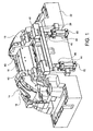
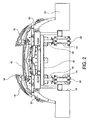
- a mould for injection-moulding of plastic parts in the example shown a mould for injection-moulding of motor-vehicle bumpers, is generally indicated 10 and basically comprises a die 12 and a punch 14 which define a cavity inside which the plastic material shall be injected by a press, in a manner known per se.
- the punch 14 comprises in turn a stationary central element 16, a first pair of movable lateral elements 18 (referred to henceforth simply as first lateral elements) arranged on longitudinally opposite sides relative to the central element 16, and a second pair of movable lateral elements 20 (referred to henceforth simply as second lateral elements) arranged on longitudinally opposite sides relative to the first lateral elements 18 and drivingly connected for translation therewith.
- the outer surfaces of the central element 16 and of the first and second lateral elements 18, 20 are suitably shaped so as to define, along with the die 12, the shape of the moulding cavity and therefore give to the part to be moulded the desired shape.
- the mould 10 also comprises a support body 22 for supporting both the die 12 and the punch 14.
- the central element 16 of the punch 14 is fixed to the support body 22, while the die 12 and the first and second lateral elements 18, 20 of the punch 14 are simply rested, in the closed mould condition, on the support body 22.
- the mould 10 also comprises a base plate 24 on which the support body 22 is mounted.
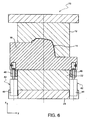
- the support body 22 has, on its bottom side, a cavity 26 which is closed at the bottom by the base plate 24 so as to form a chamber inside which an extraction plate 30 (visible in Figures 4 and 5 ) is arranged in a vertically slidable manner, guided along vertical columns 28.
- the cavity 26, and therefore the extraction plate 30, have a length (longitudinal dimension) not greater than that of the central element 16 of the punch 14. Owing to the smaller length of the cavity 26 compared to the prior art discussed in the introductory part of the present description, it is possible to reduce the projecting part of the support body 22 and therefore reduce the deformations to which the support body 22 and the central element 16 of the punch 14 are subject both as a result of their own weight and in particular as a result of the pressure exerted during moulding by the plastic material injected into the cavity formed between die 12 and punch 14.
- the first lateral elements 18 of the punch 14 are slidably guided by means of suitable guides (not shown) along respective inclined lateral surfaces 32 formed partly (top part) by the central element 16 of the punch 14 and partly (bottom part) by the support body 22 to be displaced between a moulding position (shown in Figure 4 ), in which these lateral elements are arranged with the respective outer surfaces aligned with the outer surface of the central element 16 so as to define with the latter the inner profile of the part to be moulded, and an ejection position (shown in Figures 1 and 2 ), in which these lateral elements are displaced upwards relative to the central element 16 for ejection of the moulded part.
- Each second lateral element 20 is connected to a respective first lateral element 18 by means of a longitudinal cylindrical guide 34 so as to be drivingly connected for translation with the first lateral element 18 in the vertical direction z, but free to translate relative to the first lateral element 18 in the longitudinal direction x.
- the second lateral elements 20 are moreover slidably guided by means of suitable guides (not shown) along respective inclined lateral surfaces 36 formed by the support body 22.
- the inclinations of the lateral surfaces 32 and 36 will be chosen in each case depending on the dimensions and the geometry of the undercuts of the part to be moulded and in any case may be greater than those permitted by conventional moulds.
- the mould 10 also comprises a plurality of ejection members 38 which may be equally well all of the same type or different from each other (but in any case all known per se) and which are slidably arranged each inside a respective through-hole 40 which extends partly through the support body 22 and partly through the central element 16 of the punch 14.
- the ejection members 38 are four in number in the embodiment shown in the drawings (see in particular Figure 4 ), but their number depends obviously on the specific application, in particular on the number of undercut formations which must be provided on the portion of the part to be moulded, the shape of which is defined by the outer surface of the central element 16 of the punch 14.
- Each ejection member 38 is connected at its bottom end to the extraction plate 30 so as to be displaced vertically in either direction along with the latter.
- the extraction plate 30 is a double plate, with a top plate 30a and a bottom plate 30b which can be moved independently of each other.
- some of the ejection members 38 (in the example shown the longitudinally inner members) are connected to the top plate 30a and are therefore moved together therewith, while the remaining ejection members 38 (in the example shown the longitudinally outer members) are connected to the bottom plate 30b and are therefore moved together therewith.
- the ejection members, and along with them the extraction plate (be it single or double), could also be dispensed with.
- the extraction plate 30 has merely the function of moving the ejection members 38 and not also of moving the first and second lateral elements 18, 20 of the punch 14.
- Linear actuation devices 42 are instead provided for moving the first and second lateral elements 18, 20 of the punch 14, said devices being operatively connected to the first lateral elements 18 so as to control the movement of these elements, and together therewith that of the second lateral elements 20, between the aforementioned moulding and ejection positions.
- the linear actuation devices 42 are four in number and are made as hydraulic jacks each comprising a cylinder 44 fixed to the base plate 24 and a rod 46 connected at its top end to the associated first lateral element 18.
- the rods 46 of the four linear actuation devices 42 are connected at their top end to a support frame 48 (formed for example as a rectangular frame composed of four straight bars) to which the first lateral elements 18 are fixed, whereby the first lateral elements 18 are drivingly connected for translation with each other via the support frame 48.
- a support frame 48 formed for example as a rectangular frame composed of four straight bars
- the first lateral elements 18 are drivingly connected for translation with each other via the support frame 48.
- a different number and/or different types of linear actuation devices may obviously be envisaged with respect to those described and illustrated here.
Landscapes
- Engineering & Computer Science (AREA)
- Manufacturing & Machinery (AREA)
- Mechanical Engineering (AREA)
- Moulds For Moulding Plastics Or The Like (AREA)
- Pens And Brushes (AREA)
- Injection Moulding Of Plastics Or The Like (AREA)
Claims (7)
- Moule (10) pour le moulage par injection de pièces en plastique, en particulier de pièces pour véhicule à moteur, comprenant une matrice (12) et un poinçon (14) pouvant être déplacés l'un par rapport à l'autre le long d'une direction d'ouverture/fermeture (z) entre une position de moule fermé, dans laquelle ils définissent une cavité destinée à recevoir une matière plastique injectée par une presse, et une position de moule ouvert, dans laquelle ils sont espacés l'un de l'autre d'une distance qui permet l'éjection de la pièce en plastique moulé,
dans lequel le poinçon (14) comprend un élément central fixe (16) ayant une surface extérieure et une paire de surfaces latérales (32) inclinées par rapport à la direction d'ouverture/fermeture (z), ainsi qu'une paire de premiers éléments latéraux mobiles (18) placés sur des côtés longitudinalement opposés par rapport à l'élément central (16) et ayant des surfaces extérieures respectives, les surfaces extérieures de l'élément central (16) et des premiers éléments latéraux (18) du poinçon (14) ayant une forme appropriée pour définir le profil de la pièce en plastique à mouler,
dans lequel chacun des premiers éléments latéraux (18) du poinçon (14) est guidé de façon glissante le long de la surface latérale inclinée respective (32) de l'élément central (16) du poinçon (14) à déplacer entre une position de moulage, dans laquelle la surface extérieure de l'élément latéral (18) est alignée avec la surface extérieure de l'élément central (16), et une position d'éjection, dans laquelle la surface extérieure de l'élément latéral (18) fait saillie vers l'extérieur par rapport à la surface extérieure de l'élément central (16) pour l'éjection de la pièce moulée,
dans lequel le moule (10) comprend en outre une pluralité de dispositifs d'actionnement linéaire (42) agencés pour commander le mouvement des premiers éléments latéraux (18) du poinçon (14) par rapport à l'élément central (16) entre les positions de moulage et d'éjection susmentionnées, et
dans lequel le moule (10) comprend en outre une pluralité d'éléments d'injection (38) reçus de façon glissante à l'intérieur de trous respectifs (40) prévus dans l'élément central (16) du poinçon (14), et une plaque d'extraction (30, 30a, 30b) qui peut suivre une translation dans la direction d'ouverture/fermeture du moule et qui est connectée aux éléments d'éjection (38) pour commander le mouvement glissant de ceux-ci à l'intérieur des trous respectifs (40),
le moule (10) étant caractérisé en ce que les dispositifs d'actionnement linéaire (42) sont connectés aux premiers éléments latéraux (18) du poinçon (14) sans que la plaque d'extraction (30, 30a, 30b) ne soit placée entre eux. - Moule selon la revendication 1, dans lequel les dispositifs d'actionnement linéaire (42) sont des vérins hydrauliques.
- Moule selon la revendication 1 ou 2, dans lequel les dispositifs d'actionnement linéaire (42) comprennent chacun un élément d'expulsion respectif (46) mobile dans une direction parallèle à la direction d'ouverture/fermeture (z).
- Moule selon la revendication 3, comprenant en outre un cadre de support (48) sur lequel sont fixés les premiers éléments latéraux (18), les éléments d'expulsion (46) des dispositifs d'actionnement linéaire (42) étant connectés chacun au cadre de support (48) afin d'être connectés en entraînement les uns aux autres dans le mouvement le long de la direction d'ouverture/fermeture (z).
- Moule selon l'une quelconque des revendications précédentes, dans lequel le poinçon (14) comprend en outre une paire de deuxièmes éléments latéraux (20) disposés sur des côtés longitudinalement opposés par rapport aux premiers éléments latéraux (18), dans lequel chaque deuxième élément latéral (20) est connecté à un premier élément latéral respectif (18) afin d'être connecté en entraînement pour suivre une translation avec ce dernier dans la direction d'ouverture/fermeture (z), mais libre de suivre une translation par rapport à ce dernier dans une direction longitudinale (x) du moule.
- Moule selon l'une quelconque des revendications précédentes, comprenant en outre une plaque de base (24) et un corps de support (22) monté sur la plaque de base (24) pour supporter, dans l'état du moule fermé, à la fois le poinçon (14) et la matrice (12), le corps de support (22) et la plaque de base (24) définissant une chambre (26) à l'intérieur de laquelle est disposée la plaque d'extraction (30, 30a, 30b).
- Moule selon la revendication 6, dans lequel la longueur ou dimension longitudinale de la chambre (26) n'est pas supérieure à celle de l'élément central (16) du poinçon (14).
Applications Claiming Priority (2)
| Application Number | Priority Date | Filing Date | Title |
|---|---|---|---|
| ITTO2010A000066A IT1398402B1 (it) | 2010-01-29 | 2010-01-29 | Stampo per lo stampaggio a iniezione di parti di plastica. |
| PCT/IB2011/050373 WO2011092650A1 (fr) | 2010-01-29 | 2011-01-28 | Moule pour le moulage par injection de pièces de matière plastique |
Publications (2)
| Publication Number | Publication Date |
|---|---|
| EP2528722A1 EP2528722A1 (fr) | 2012-12-05 |
| EP2528722B1 true EP2528722B1 (fr) | 2013-12-11 |
Family
ID=42671888
Family Applications (1)
| Application Number | Title | Priority Date | Filing Date |
|---|---|---|---|
| EP11709469.8A Not-in-force EP2528722B1 (fr) | 2010-01-29 | 2011-01-28 | Moule pour le moulage par injection de pièces de matière plastique |
Country Status (8)
| Country | Link |
|---|---|
| US (1) | US20130129857A1 (fr) |
| EP (1) | EP2528722B1 (fr) |
| BR (1) | BR112012018977A2 (fr) |
| CA (1) | CA2786177A1 (fr) |
| ES (1) | ES2451580T3 (fr) |
| IT (1) | IT1398402B1 (fr) |
| RU (1) | RU2012136837A (fr) |
| WO (1) | WO2011092650A1 (fr) |
Families Citing this family (1)
| Publication number | Priority date | Publication date | Assignee | Title |
|---|---|---|---|---|
| FR3038248B1 (fr) * | 2015-07-02 | 2017-12-22 | Reydel Automotive Bv | Procede et dispositif pour la fabrication d'une piece hybride ou composite a base de materiau thermoplastique presentant une face d'aspect et une face technique |
Family Cites Families (3)
| Publication number | Priority date | Publication date | Assignee | Title |
|---|---|---|---|---|
| FR2809344B1 (fr) * | 2000-05-24 | 2002-08-23 | Ecia Equip Composants Ind Auto | Moule d'injection a demoulage par deformation |
| JP4774878B2 (ja) * | 2005-09-08 | 2011-09-14 | マツダ株式会社 | 射出成形品の製造装置およびその製造方法 |
| WO2008084128A1 (fr) * | 2007-01-10 | 2008-07-17 | Mecanoplastica, S.A. | Appareil et procédé de démoulage de pièces plastiques par expulsion frontale |
-
2010
- 2010-01-29 IT ITTO2010A000066A patent/IT1398402B1/it active
-
2011
- 2011-01-28 US US13/521,068 patent/US20130129857A1/en not_active Abandoned
- 2011-01-28 RU RU2012136837/05A patent/RU2012136837A/ru not_active Application Discontinuation
- 2011-01-28 ES ES11709469.8T patent/ES2451580T3/es active Active
- 2011-01-28 BR BR112012018977A patent/BR112012018977A2/pt not_active IP Right Cessation
- 2011-01-28 WO PCT/IB2011/050373 patent/WO2011092650A1/fr not_active Ceased
- 2011-01-28 CA CA2786177A patent/CA2786177A1/fr not_active Abandoned
- 2011-01-28 EP EP11709469.8A patent/EP2528722B1/fr not_active Not-in-force
Also Published As
| Publication number | Publication date |
|---|---|
| ES2451580T3 (es) | 2014-03-27 |
| US20130129857A1 (en) | 2013-05-23 |
| WO2011092650A1 (fr) | 2011-08-04 |
| EP2528722A1 (fr) | 2012-12-05 |
| RU2012136837A (ru) | 2014-03-10 |
| CA2786177A1 (fr) | 2011-04-08 |
| IT1398402B1 (it) | 2013-02-22 |
| BR112012018977A2 (pt) | 2018-03-27 |
| ITTO20100066A1 (it) | 2011-07-30 |
Similar Documents
| Publication | Publication Date | Title |
|---|---|---|
| RU2385227C2 (ru) | Инструмент для литьевого формования пластмассы | |
| KR20140037840A (ko) | 언더컷 처리 기구 | |
| JP2009208091A (ja) | 成型装置 | |
| EP2528722B1 (fr) | Moule pour le moulage par injection de pièces de matière plastique | |
| EP3326780B1 (fr) | Mécanisme de traitement de contre-dépouille et matrice de moulage | |
| EP2454068B1 (fr) | Moulage d'injection pour elemente en matiére plastique avec contre-dépouille et une système d'éjection integrée | |
| EP0949022A1 (fr) | Outile de moulage | |
| JP6968863B2 (ja) | 金属材料を直接押し出すためのプレス | |
| CN112606339B (zh) | 倒扣脱模机构和注塑模具 | |
| JP2008525238A (ja) | 金型および製品成形方法 | |
| KR102037620B1 (ko) | 수지성형장치용 고정 플래튼, 수지성형장치 및 수지성형장치용 고정 플래튼의 제조 방법 | |
| CN112026115A (zh) | 一种可在模具开合模时控制定模滑块抽芯先后顺序的结构 | |
| ITMI20090056A1 (it) | Pressa per lo stampaggio a caldo di billette e simili. | |
| KR100628552B1 (ko) | 가압성형기 | |
| KR101946240B1 (ko) | 냉장고 케이스 제조용 높이 가변형 공용 발포 금형 | |
| KR100934616B1 (ko) | 냉장고 케이스의 발포 금형 | |
| CN212242003U (zh) | 一种可在模具开合模时控制定模滑块抽芯先后顺序的结构 | |
| KR20120087729A (ko) | 조리용기 제조용 중력주조장치 | |
| CN102328415B (zh) | 动模内置油缸纵向驱动双联滑块斜抽芯装置 | |
| US1708178A (en) | Press for forming plastic articles | |
| CN101132899A (zh) | 用于形成塑料产品的模具和方法 | |
| JP6015495B2 (ja) | 粉末成形装置 | |
| CN209141367U (zh) | 一种手机壳加工模具的顶出机构 | |
| CN220742029U (zh) | 一种壳体的模具 | |
| CN221417309U (zh) | 一种具有多个侧抽机构的模具 |
Legal Events
| Date | Code | Title | Description |
|---|---|---|---|
| PUAI | Public reference made under article 153(3) epc to a published international application that has entered the european phase |
Free format text: ORIGINAL CODE: 0009012 |
|
| 17P | Request for examination filed |
Effective date: 20120802 |
|
| AK | Designated contracting states |
Kind code of ref document: A1 Designated state(s): AL AT BE BG CH CY CZ DE DK EE ES FI FR GB GR HR HU IE IS IT LI LT LU LV MC MK MT NL NO PL PT RO RS SE SI SK SM TR |
|
| DAX | Request for extension of the european patent (deleted) | ||
| GRAP | Despatch of communication of intention to grant a patent |
Free format text: ORIGINAL CODE: EPIDOSNIGR1 |
|
| INTG | Intention to grant announced |
Effective date: 20130627 |
|
| GRAS | Grant fee paid |
Free format text: ORIGINAL CODE: EPIDOSNIGR3 |
|
| GRAA | (expected) grant |
Free format text: ORIGINAL CODE: 0009210 |
|
| RAP1 | Party data changed (applicant data changed or rights of an application transferred) |
Owner name: H.C.M. STAMPI S.R.L. |
|
| AK | Designated contracting states |
Kind code of ref document: B1 Designated state(s): AL AT BE BG CH CY CZ DE DK EE ES FI FR GB GR HR HU IE IS IT LI LT LU LV MC MK MT NL NO PL PT RO RS SE SI SK SM TR |
|
| REG | Reference to a national code |
Ref country code: GB Ref legal event code: FG4D |
|
| REG | Reference to a national code |
Ref country code: CH Ref legal event code: EP |
|
| REG | Reference to a national code |
Ref country code: AT Ref legal event code: REF Ref document number: 644253 Country of ref document: AT Kind code of ref document: T Effective date: 20140115 |
|
| REG | Reference to a national code |
Ref country code: IE Ref legal event code: FG4D |
|
| REG | Reference to a national code |
Ref country code: DE Ref legal event code: R096 Ref document number: 602011004170 Country of ref document: DE Effective date: 20140206 |
|
| REG | Reference to a national code |
Ref country code: SE Ref legal event code: TRGR |
|
| REG | Reference to a national code |
Ref country code: ES Ref legal event code: FG2A Ref document number: 2451580 Country of ref document: ES Kind code of ref document: T3 Effective date: 20140327 |
|
| REG | Reference to a national code |
Ref country code: NL Ref legal event code: VDEP Effective date: 20131211 |
|
| REG | Reference to a national code |
Ref country code: AT Ref legal event code: MK05 Ref document number: 644253 Country of ref document: AT Kind code of ref document: T Effective date: 20131211 |
|
| PG25 | Lapsed in a contracting state [announced via postgrant information from national office to epo] |
Ref country code: HR Free format text: LAPSE BECAUSE OF FAILURE TO SUBMIT A TRANSLATION OF THE DESCRIPTION OR TO PAY THE FEE WITHIN THE PRESCRIBED TIME-LIMIT Effective date: 20131211 Ref country code: LT Free format text: LAPSE BECAUSE OF FAILURE TO SUBMIT A TRANSLATION OF THE DESCRIPTION OR TO PAY THE FEE WITHIN THE PRESCRIBED TIME-LIMIT Effective date: 20131211 Ref country code: NO Free format text: LAPSE BECAUSE OF FAILURE TO SUBMIT A TRANSLATION OF THE DESCRIPTION OR TO PAY THE FEE WITHIN THE PRESCRIBED TIME-LIMIT Effective date: 20140311 Ref country code: FI Free format text: LAPSE BECAUSE OF FAILURE TO SUBMIT A TRANSLATION OF THE DESCRIPTION OR TO PAY THE FEE WITHIN THE PRESCRIBED TIME-LIMIT Effective date: 20131211 Ref country code: NL Free format text: LAPSE BECAUSE OF FAILURE TO SUBMIT A TRANSLATION OF THE DESCRIPTION OR TO PAY THE FEE WITHIN THE PRESCRIBED TIME-LIMIT Effective date: 20131211 |
|
| REG | Reference to a national code |
Ref country code: LT Ref legal event code: MG4D |
|
| PG25 | Lapsed in a contracting state [announced via postgrant information from national office to epo] |
Ref country code: RS Free format text: LAPSE BECAUSE OF FAILURE TO SUBMIT A TRANSLATION OF THE DESCRIPTION OR TO PAY THE FEE WITHIN THE PRESCRIBED TIME-LIMIT Effective date: 20131211 Ref country code: LV Free format text: LAPSE BECAUSE OF FAILURE TO SUBMIT A TRANSLATION OF THE DESCRIPTION OR TO PAY THE FEE WITHIN THE PRESCRIBED TIME-LIMIT Effective date: 20131211 Ref country code: CY Free format text: LAPSE BECAUSE OF FAILURE TO SUBMIT A TRANSLATION OF THE DESCRIPTION OR TO PAY THE FEE WITHIN THE PRESCRIBED TIME-LIMIT Effective date: 20131211 Ref country code: AT Free format text: LAPSE BECAUSE OF FAILURE TO SUBMIT A TRANSLATION OF THE DESCRIPTION OR TO PAY THE FEE WITHIN THE PRESCRIBED TIME-LIMIT Effective date: 20131211 |
|
| PG25 | Lapsed in a contracting state [announced via postgrant information from national office to epo] |
Ref country code: IS Free format text: LAPSE BECAUSE OF FAILURE TO SUBMIT A TRANSLATION OF THE DESCRIPTION OR TO PAY THE FEE WITHIN THE PRESCRIBED TIME-LIMIT Effective date: 20140411 Ref country code: BE Free format text: LAPSE BECAUSE OF FAILURE TO SUBMIT A TRANSLATION OF THE DESCRIPTION OR TO PAY THE FEE WITHIN THE PRESCRIBED TIME-LIMIT Effective date: 20131211 Ref country code: EE Free format text: LAPSE BECAUSE OF FAILURE TO SUBMIT A TRANSLATION OF THE DESCRIPTION OR TO PAY THE FEE WITHIN THE PRESCRIBED TIME-LIMIT Effective date: 20131211 |
|
| PG25 | Lapsed in a contracting state [announced via postgrant information from national office to epo] |
Ref country code: PT Free format text: LAPSE BECAUSE OF FAILURE TO SUBMIT A TRANSLATION OF THE DESCRIPTION OR TO PAY THE FEE WITHIN THE PRESCRIBED TIME-LIMIT Effective date: 20140411 Ref country code: PL Free format text: LAPSE BECAUSE OF FAILURE TO SUBMIT A TRANSLATION OF THE DESCRIPTION OR TO PAY THE FEE WITHIN THE PRESCRIBED TIME-LIMIT Effective date: 20131211 Ref country code: RO Free format text: LAPSE BECAUSE OF FAILURE TO SUBMIT A TRANSLATION OF THE DESCRIPTION OR TO PAY THE FEE WITHIN THE PRESCRIBED TIME-LIMIT Effective date: 20131211 Ref country code: SK Free format text: LAPSE BECAUSE OF FAILURE TO SUBMIT A TRANSLATION OF THE DESCRIPTION OR TO PAY THE FEE WITHIN THE PRESCRIBED TIME-LIMIT Effective date: 20131211 Ref country code: LU Free format text: LAPSE BECAUSE OF FAILURE TO SUBMIT A TRANSLATION OF THE DESCRIPTION OR TO PAY THE FEE WITHIN THE PRESCRIBED TIME-LIMIT Effective date: 20140128 |
|
| REG | Reference to a national code |
Ref country code: CH Ref legal event code: PL |
|
| REG | Reference to a national code |
Ref country code: DE Ref legal event code: R097 Ref document number: 602011004170 Country of ref document: DE |
|
| PG25 | Lapsed in a contracting state [announced via postgrant information from national office to epo] |
Ref country code: MC Free format text: LAPSE BECAUSE OF FAILURE TO SUBMIT A TRANSLATION OF THE DESCRIPTION OR TO PAY THE FEE WITHIN THE PRESCRIBED TIME-LIMIT Effective date: 20131211 |
|
| PLBE | No opposition filed within time limit |
Free format text: ORIGINAL CODE: 0009261 |
|
| STAA | Information on the status of an ep patent application or granted ep patent |
Free format text: STATUS: NO OPPOSITION FILED WITHIN TIME LIMIT |
|
| PG25 | Lapsed in a contracting state [announced via postgrant information from national office to epo] |
Ref country code: LI Free format text: LAPSE BECAUSE OF NON-PAYMENT OF DUE FEES Effective date: 20140131 Ref country code: DK Free format text: LAPSE BECAUSE OF FAILURE TO SUBMIT A TRANSLATION OF THE DESCRIPTION OR TO PAY THE FEE WITHIN THE PRESCRIBED TIME-LIMIT Effective date: 20131211 Ref country code: CH Free format text: LAPSE BECAUSE OF NON-PAYMENT OF DUE FEES Effective date: 20140131 |
|
| REG | Reference to a national code |
Ref country code: IE Ref legal event code: MM4A |
|
| 26N | No opposition filed |
Effective date: 20140912 |
|
| REG | Reference to a national code |
Ref country code: DE Ref legal event code: R097 Ref document number: 602011004170 Country of ref document: DE Effective date: 20140912 |
|
| PG25 | Lapsed in a contracting state [announced via postgrant information from national office to epo] |
Ref country code: IE Free format text: LAPSE BECAUSE OF NON-PAYMENT OF DUE FEES Effective date: 20140128 |
|
| PG25 | Lapsed in a contracting state [announced via postgrant information from national office to epo] |
Ref country code: SI Free format text: LAPSE BECAUSE OF FAILURE TO SUBMIT A TRANSLATION OF THE DESCRIPTION OR TO PAY THE FEE WITHIN THE PRESCRIBED TIME-LIMIT Effective date: 20131211 |
|
| REG | Reference to a national code |
Ref country code: FR Ref legal event code: PLFP Year of fee payment: 6 |
|
| PG25 | Lapsed in a contracting state [announced via postgrant information from national office to epo] |
Ref country code: MT Free format text: LAPSE BECAUSE OF FAILURE TO SUBMIT A TRANSLATION OF THE DESCRIPTION OR TO PAY THE FEE WITHIN THE PRESCRIBED TIME-LIMIT Effective date: 20131211 |
|
| PG25 | Lapsed in a contracting state [announced via postgrant information from national office to epo] |
Ref country code: SM Free format text: LAPSE BECAUSE OF FAILURE TO SUBMIT A TRANSLATION OF THE DESCRIPTION OR TO PAY THE FEE WITHIN THE PRESCRIBED TIME-LIMIT Effective date: 20131211 |
|
| PG25 | Lapsed in a contracting state [announced via postgrant information from national office to epo] |
Ref country code: BG Free format text: LAPSE BECAUSE OF FAILURE TO SUBMIT A TRANSLATION OF THE DESCRIPTION OR TO PAY THE FEE WITHIN THE PRESCRIBED TIME-LIMIT Effective date: 20131211 Ref country code: GR Free format text: LAPSE BECAUSE OF FAILURE TO SUBMIT A TRANSLATION OF THE DESCRIPTION OR TO PAY THE FEE WITHIN THE PRESCRIBED TIME-LIMIT Effective date: 20140312 |
|
| PG25 | Lapsed in a contracting state [announced via postgrant information from national office to epo] |
Ref country code: TR Free format text: LAPSE BECAUSE OF FAILURE TO SUBMIT A TRANSLATION OF THE DESCRIPTION OR TO PAY THE FEE WITHIN THE PRESCRIBED TIME-LIMIT Effective date: 20131211 Ref country code: HU Free format text: LAPSE BECAUSE OF FAILURE TO SUBMIT A TRANSLATION OF THE DESCRIPTION OR TO PAY THE FEE WITHIN THE PRESCRIBED TIME-LIMIT; INVALID AB INITIO Effective date: 20110128 |
|
| REG | Reference to a national code |
Ref country code: FR Ref legal event code: PLFP Year of fee payment: 7 |
|
| REG | Reference to a national code |
Ref country code: FR Ref legal event code: PLFP Year of fee payment: 8 |
|
| PG25 | Lapsed in a contracting state [announced via postgrant information from national office to epo] |
Ref country code: MK Free format text: LAPSE BECAUSE OF FAILURE TO SUBMIT A TRANSLATION OF THE DESCRIPTION OR TO PAY THE FEE WITHIN THE PRESCRIBED TIME-LIMIT Effective date: 20131211 |
|
| PG25 | Lapsed in a contracting state [announced via postgrant information from national office to epo] |
Ref country code: AL Free format text: LAPSE BECAUSE OF FAILURE TO SUBMIT A TRANSLATION OF THE DESCRIPTION OR TO PAY THE FEE WITHIN THE PRESCRIBED TIME-LIMIT Effective date: 20131211 |
|
| PGFP | Annual fee paid to national office [announced via postgrant information from national office to epo] |
Ref country code: CZ Payment date: 20181126 Year of fee payment: 9 |
|
| PGFP | Annual fee paid to national office [announced via postgrant information from national office to epo] |
Ref country code: FR Payment date: 20190131 Year of fee payment: 9 Ref country code: ES Payment date: 20190201 Year of fee payment: 9 Ref country code: GB Payment date: 20190121 Year of fee payment: 9 Ref country code: IT Payment date: 20181126 Year of fee payment: 9 |
|
| PGFP | Annual fee paid to national office [announced via postgrant information from national office to epo] |
Ref country code: SE Payment date: 20190116 Year of fee payment: 9 |
|
| PGFP | Annual fee paid to national office [announced via postgrant information from national office to epo] |
Ref country code: DE Payment date: 20190401 Year of fee payment: 9 |
|
| REG | Reference to a national code |
Ref country code: DE Ref legal event code: R119 Ref document number: 602011004170 Country of ref document: DE |
|
| REG | Reference to a national code |
Ref country code: SE Ref legal event code: EUG |
|
| GBPC | Gb: european patent ceased through non-payment of renewal fee |
Effective date: 20200128 |
|
| REG | Reference to a national code |
Ref country code: SE Ref legal event code: EUG |
|
| PG25 | Lapsed in a contracting state [announced via postgrant information from national office to epo] |
Ref country code: CZ Free format text: LAPSE BECAUSE OF NON-PAYMENT OF DUE FEES Effective date: 20200128 Ref country code: DE Free format text: LAPSE BECAUSE OF NON-PAYMENT OF DUE FEES Effective date: 20200801 Ref country code: SE Free format text: LAPSE BECAUSE OF NON-PAYMENT OF DUE FEES Effective date: 20200129 Ref country code: GB Free format text: LAPSE BECAUSE OF NON-PAYMENT OF DUE FEES Effective date: 20200128 Ref country code: FR Free format text: LAPSE BECAUSE OF NON-PAYMENT OF DUE FEES Effective date: 20200131 |
|
| PG25 | Lapsed in a contracting state [announced via postgrant information from national office to epo] |
Ref country code: IT Free format text: LAPSE BECAUSE OF NON-PAYMENT OF DUE FEES Effective date: 20200128 |
|
| REG | Reference to a national code |
Ref country code: ES Ref legal event code: FD2A Effective date: 20210607 |
|
| PG25 | Lapsed in a contracting state [announced via postgrant information from national office to epo] |
Ref country code: ES Free format text: LAPSE BECAUSE OF NON-PAYMENT OF DUE FEES Effective date: 20200129 |