EP2529193B1 - Assemblage de mesure à taux de couple variable - Google Patents
Assemblage de mesure à taux de couple variable Download PDFInfo
- Publication number
- EP2529193B1 EP2529193B1 EP11700282.4A EP11700282A EP2529193B1 EP 2529193 B1 EP2529193 B1 EP 2529193B1 EP 11700282 A EP11700282 A EP 11700282A EP 2529193 B1 EP2529193 B1 EP 2529193B1
- Authority
- EP
- European Patent Office
- Prior art keywords
- test
- nut
- screw
- joint
- bolt
- Prior art date
- Legal status (The legal status is an assumption and is not a legal conclusion. Google has not performed a legal analysis and makes no representation as to the accuracy of the status listed.)
- Active
Links
Images


Classifications
-
- G—PHYSICS
- G01—MEASURING; TESTING
- G01L—MEASURING FORCE, STRESS, TORQUE, WORK, MECHANICAL POWER, MECHANICAL EFFICIENCY, OR FLUID PRESSURE
- G01L5/00—Apparatus for, or methods of, measuring force, work, mechanical power, or torque, specially adapted for specific purposes
- G01L5/24—Apparatus for, or methods of, measuring force, work, mechanical power, or torque, specially adapted for specific purposes for determining value of torque or twisting moment for tightening a nut or other member which is similarly stressed
-
- G—PHYSICS
- G01—MEASURING; TESTING
- G01C—MEASURING DISTANCES, LEVELS OR BEARINGS; SURVEYING; NAVIGATION; GYROSCOPIC INSTRUMENTS; PHOTOGRAMMETRY OR VIDEOGRAMMETRY
- G01C17/00—Compasses; Devices for ascertaining true or magnetic north for navigation or surveying purposes
-
- G—PHYSICS
- G01—MEASURING; TESTING
- G01L—MEASURING FORCE, STRESS, TORQUE, WORK, MECHANICAL POWER, MECHANICAL EFFICIENCY, OR FLUID PRESSURE
- G01L25/00—Testing or calibrating of apparatus for measuring force, torque, work, mechanical power, or mechanical efficiency
- G01L25/003—Testing or calibrating of apparatus for measuring force, torque, work, mechanical power, or mechanical efficiency for measuring torque
-
- G—PHYSICS
- G01—MEASURING; TESTING
- G01L—MEASURING FORCE, STRESS, TORQUE, WORK, MECHANICAL POWER, MECHANICAL EFFICIENCY, OR FLUID PRESSURE
- G01L5/00—Apparatus for, or methods of, measuring force, work, mechanical power, or torque, specially adapted for specific purposes
- G01L5/24—Apparatus for, or methods of, measuring force, work, mechanical power, or torque, specially adapted for specific purposes for determining value of torque or twisting moment for tightening a nut or other member which is similarly stressed
- G01L5/243—Apparatus for, or methods of, measuring force, work, mechanical power, or torque, specially adapted for specific purposes for determining value of torque or twisting moment for tightening a nut or other member which is similarly stressed using washers
Definitions
- the invention relates to test joints for the performance testing of rotary tools for threaded fasteners.
- the invention provides such a test joint with a variable torque-rate.
- the bolted joint is a very important fastener method in modern engineering assemblies. It works by screwing together two or more parts with a bolt and nut.
- the bolt or nut may be made integral with one of those parts, and the screwing action draws the bolt and nut together so that their faces produce a clamping force.
- the bolt material can stretch or the material forming the parts being fastened together may compress, as the nut is tightened. It is very difficult to measure the precise extent of the above stretching or compression, and therefore to deduce the resulting clamping force. Experiments are therefore performed with force washers to arrive at a torque value which is easy to measure, so as to establish that the clamping force is between specified limits.
- test joint a bolted joint with known characteristics
- rotary fasteners used to tighten up the test joints are also periodically checked, to make sure they are set up correctly before they are used on an assembly line.
- JRSs Joint Rate Simulators
- a JRS uses this characteristic to provide a test piece on which the tool will fit, such that when the tool applies torque to turn the test piece, that torque increases with the angle through which the bolt turns.
- the rate of increase of torque with increasing angle is referred to as the torque-rate.
- a joint with a high torque-rate is referred to as a "hard joint”, and full tightening is generally accomplished in a fraction of a revolution.
- a low torque-rate joint (known as a "soft joint) the full tightening is usually accomplished over a much greater angular range of movement, possibly several complete revolutions of fastener.
- Test joints are known in which a rotatable shaft is physically braked, with the braking effort increasing as a function of rotation.
- the braking effort which can be achieved either by brake shoes engaging the outer cylindrical surface of the shaft or by brake pads engaging opposite surfaces of a brake disc carried by the shaft, can be varied to simulate either a hard or a soft joint.
- Our own WO98/10260 is an example of such a variable rate JRS. It allows the test joint parameters to be easily changed, allowing any test joint to be simulated; and it allows the torque to be removed after the joint has been tightened, so that a subsequent cycle of the performance testing routine can take place without any time delay. Any complete performance testing routine comprises a number of repeated tightening cycles of the test joint, with the results being averaged or statistically analyzed.
- the disparity between the moment of inertia of the JRS and that of the real joint which it simulates increases when the mechanism for braking the test joint involves calliper brake pads braking against opposite sides of a brake disc. Disparities between the moment of inertia of the test joint and the moment of inertia of the real joint become particularly important when the test joint is used for the performance testing of impulse drive tools. These tools rely on the transfer of pulses of torque, each pulse being a few milliseconds in duration, with many pulses per second being applied to the joint. If the joint has a large moment of inertia, then the tool cannot transfer enough energy to make the joint initially free-turn before the joint tightens, and the tool can then stall.
- JRSs with disc brakes suffer from this specific problem, and even JRSs with drum brakes clamping against opposite sides of a shaft can have moments of inertia that are not matched to that of the real joint under simulation, and so will not necessarily give true results for impulse tools.
- the invention of our own WO2008/099204 provides a variable torque-rate test joint which has a working moment of inertia that is more closely matched to that of a screw-threaded bolt which it simulates. That compliance between the moment of inertia of the JRS and that of the joint under simulation is achieved by using, for the rotary component of the JRS to be driven by the rotary tool, a screw threaded bolt, the size and inertia of which can be accurately matched with that of the bolt of the joint under simulation.
- the test joint according to WO2008/099204 utilises a screw-threaded nut and bolt on a test rig, the bolt being adapted to be tightened by a rotary tool under test against a variable joint supported by the nut.
- the variable joint comprises a spring beam which extends in cantilever over a pivot point to engage beneath a head of the bolt. If the pivot point is close to the bolt head then that simulates a hard joint, whereas if the pivot point is more distant from the bolt then the joint becomes progressively more soft.
- the end of the spring beam remote from the bolt is anchored, either fast to the test rig or fast to the corresponding end of a second spring beam which extends in cantilever past the same pivot point to engage with a nut into which the bolt is screwed.
- the bolt is screwed down against the variable joint, with the applied torque being carefully monitored over the whole angular range of progressive tightening of the bolt.
- the bolt must be screwed back to its start position and the tightening process is repeated.
- a typical test sequence would involve a statistically significant number of repeated tightening processes.
- WO2008/099204 discloses a cam arrangement for the release of the joint compression at the end of each tightening sequence, to permit a rapid run-back of the tightened bolt after each monitored tightening sequence.
- variable torque-rate test joint simulates a very massive bolt such as may be included in constructional ironwork or in very heavy machinery.
- cams of WP2008/099204 are sent slightly over-centre to lock the distal ends of the spring beams, so that they do not disengage accidentally.
- the pressure of the tightened bolt may be so great that it becomes very difficult or impossible to release those cams at the end of the test sequence, because their release requires the cams to pass once again over-centre to move to their release positions, with an attendant momentary small increase in the pressure applied by the test joint. It is therefore an object of the invention to create a variable torque-rate test joint which has an easily operable release mechanism which is suitable for use over the entire range of test bolt sizes, from small to even the most massive threaded joints.
- the invention provides a variable torque-rate test joint for the performance testing of rotary tools for threaded fasteners, as defined in claim 1 herein.
- test joint of the invention it is preferably the nut and not the bolt of the nut and bolt assembly which is adapted to be tightened by the rotary tool under test.
- a nut has a potentially lower moment of inertia than the screw-threaded shank on which it is screw-threaded, and so the designer has more control over the moment of inertial of the test joint if it is the nut which is engaged and turned by the tool under test.
- a variable torque-rate test joint according to the invention can be designed to be suitable for a range of torques and a range of joint rates.
- the variable torque-rate test joint comprises a nut and bolt assembly consisting of a nut 1 screw-threaded to a threaded shaft 2.
- the nut 1 is the component of the test joint which is adapted to be engaged by and tightened by a rotary tool under test.
- the tool not shown in the drawings, engages the hexagonal head of the nut through the intermediary of a torque sensor and tightens the nut on the threaded shaft.
- the torque sensor enables a precise correlation to be made between the torque applied to the nut 1 and the angular rotation of the nut 1 on the shaft 2, which in turn provides a test regime to calibrating the rotary tool.
- the nut is tightened on the shaft until a maximum torque is applied, then released by unwinding to relieve the pressure, and the whole regime repeated until the user has available the results of several test sequences.
- the nut 1 and shaft 2 are arranged to compress a variable joint 3 against a reaction surface 4, as follows.
- the threaded shaft 2 has a hexagonal head 5 which is received in a co-operating hexagonal recess in an anchorage member 6.
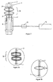
- the shaft 2 and head 5 are illustrated more clearly in Figure 6 , which is not drawn to scale.
- the hexagonal head 5 is shown in Figures 1 to 4 as being retained in the recess in the anchorage member 6 by a transverse pin 7 passing through aligned bores in the head and anchorage member 6, although any other retention means may be used in place of the pin 7.
- the shaft head 5 and the recess in the anchorage member 6 could alternatively be both square, or be any other shapes that co-operate to prevent relative rotation between the respective parts.
- anchorage of the threaded shaft 2 to the anchorage member 6 is possible.
- a fork or screw cap on the anchorage member 6 could overlie the head 5 of the threaded shaft 2, thus retaining the shaft head 5 in its shaped recess.
- the anchorage member 6 has a shoulder 8 on which is seated an annular cylinder 9.
- a hydraulic seal is created between the anchorage member 6 and the cylinder 9 so as to create within the cylinder 9 an annular hydraulic chamber 10 surrounding the anchorage member 6.
- An alternative to this system would be to use an internal sleeve that provides the hydraulic seal and defines the inner wall of the hydraulic chamber, with anchorage member 6 running through the sleeve
- An annular piston 11 is located at the top end of the cylinder 9.
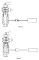
- the anchorage member 6 passes axially through aligned bores in the cylinder 9 and piston 11, so that the piston 11 can be extended from the cylinder 9 as shown in Figures 1 and 2 or retracted into the cylinder 9 as shown in Figures 3 and 4 , under the action of hydraulic fluid under pressure from a pressure source 12 and a three-position control valve 13.
- Figures 1 to 3 show the three alternative conditions of the control valve 13.
- the hydraulic supply 12 is activated and the control valve passes hydraulic fluid from the pressure source 12 to the hydraulic chamber 10.
- In Figure 2 it is closed against both supply and return of the hydraulic fluid, effectively locking the piston 11 hydraulically against movement relative to the cylinder 9.
- FIGs 3 and 4 the hydraulic chamber 10 is connected to drain, so that the piston 11 is freely movable in the cylinder 9.
- An alternative to using a three-position valve 13 as illustrated in the drawings would be to use a two-position valve which is either open as in Figure 1 to connect the hydraulic supply 12 to the hydraulic chamber 10 or closed as in Figure 2 to isolate the hydraulic chamber 10.
- the hydraulic 12 supply would be a hydraulic pump which would be operative and the valve 13 open in the set-up configuration of Figure 1 , but the valve closed and the pump inoperative in the test condition of Figure 2 .
- the valve 13 would again be open, but with the pump inoperative, so that the hydraulic fluid in the hydraulic chamber 10 simply passes back to the pump.
- the top annular edge of the piston 11 forms the reaction surface 4 referred to above, and between the nut and the reaction surface 4 is the variable joint 3.
- the device 3 comprises a pair of spring beams 14, 15 secured together at one end (the end remote from the nut 1 and threaded shank 2) by a bolt 16. At an intermediate location the beams 14, 15 pass over and under a pivot member 17, so that they extend in cantilever over and under the pivot member 17 to receive the compressive force of the nut 1 and threaded shaft 2.
- the hardness or softness of the resulting joint is determined by the relative spacing of the pivot member 17 relative to the ends of the spring beams 14, 15. If the pivot member is close to the axis of the threaded shaft 2, then the joint is harder than if it is moved towards the bolt 16.
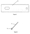
- Each spring beam 14 or 15 has the general outline as shown in Figure 5 .
- a hole is formed at one end for connection together of the two spring beams 14, 15 by the bolt 16, and an elongate hole at the other end is formed through which the threaded shaft 2 can pass without contact with the side wall of the elongate hole.
- the spring beams 14, 15 bend as shown in Figure 2 . Twisting of the threaded shaft 2 is avoided or reduced to a minimum by placing two washer pairs 18 between the nut 1 and the beam 14 and between the reaction surface 4 and the beam 15.
- the washer pairs 18 each comprise a washer with a part-spherical convex surface which seats against a corresponding part-spherical concave surface of the other washer of the pair, so that one part-spherical surface can slide over the other (the washer sets being arranged loosely around the threaded shaft 2). Accordingly, the change in the angular orientation of the ends of the beams 14,15 as the beams flex is not transmitted as a flexing moment to the shaft 2, as illustrated in Figure 2 .
- the nut is tightened against the variable joint 3 using the rotary tool under test, and the torque applied to the nut 1 and the angle through which the nut moves is plotted as a graph or table of results.
- the closeness of that graph or table to the intended performance characteristics of the tool under test provide a measure of accuracy of the torque setting of the tool for a joint of the relevant degree of hardness/softness.
- the test must be repeated many times in order to obtain statistically relevant results. Before it can be repeated the nut 1 must be unwound from the shaft 2.
- Some rotary tools do not have a reverse setting, so that the unwinding of the nut 1 must be performed manually.
- test joint of the invention therefore incorporates means for relieving the pressure on the beams 14, 15 hydraulically.
- the control valve is set to the pressure relief condition of Figure 3 , and the piston 11 immediately retracts, relieving all of the applied pressure.
- the nut 1 can then be wound back easily either by hand, by the tool under test or by rotating the anchorage member 6 for example by an electric motor.
- the pressure on the joint has been released even before this winding back commences, and the return to the condition of Figure 1 is achieved swiftly and with a minimum expenditure of energy.
- the anchorage member 6 must be held against rotation during the test sequence while the nut 1 is being tightened by the tool under test, so that if the winding back at the end of the test is to be obtained by turning the anchorage member (which is shown as having a hexagonal head beneath the cylinder 9), then there must be a ratchet or similar anchorage (not shown) to allow that turning of the anchorage member during the winding back sequence but holding it against rotation during the test sequence. Otherwise, the anchorage member 6 would have to be clamped against rotation at all times.
- Figures 1 to 4 also show an optional modification to the test joint as described above.
- a cylinder 20 is mounted at the left-hand end of the beam 15 as illustrated, immediately adjacent the threaded shaft 2.
- a piston 21 can be hydraulically or pneumatically extended from that cylinder as shown in Figure 4 when the test joint has been returned to its initial position.
- Figure 4 shows in a very exaggerated fashion the result of that extension.
- the top beam 14 is lifted away from the pivot member 17, which makes it significantly easier for the pivot member 17 to be moved in the direction of the arrow A to vary the hardness of the simulated joint.
- Figures 1 to 4 also show another optional modification which greatly extends the usefulness of the test joint as so far described.
- a strain gauge 25 Built in to the anchorage member 6 is a strain gauge 25. That measures the actual linear strain in the anchorage member, which is a direct measure of the compressive force created by the rotary tool under test when used on the test joint. A torque gauge between the rotary tool and the nut 1 will measure both the torque and the angular rotation for each torque output. Without the strain gauge 25 however the actual compressive force of the joint would have to be calculated from the applied torque or the amount of angular rotation. Using the strain gauge 25 that calculation is redundant or in the alternative its accuracy can be checked directly, which is a great benefit in tool calibration & tool performance assessment.
- an alternative procedure can be used for determining the compressive force in the test joint based on a measurement of the deflection of the beams 14,15.
- a measurement of the distance between the upper and lower beams as they bend under compression determines the extent through which they have moved from their rest positions.
- the properties of the beams are well known so from their deflection it is straightforward to calculate the compressive force exerted on them and the equal reactive force that they exert on the test joint.
- the distance measurement can in principle be made at any location along the beams between the pivot 17 and their free ends but the preferred location is close to the threaded shaft 2, where the compressive force is applied to the beams.
- One simple way to determine the distance through which the beams 14,15 have been deflected is to use the aforementioned torque gauge between the rotary tool under test and the nut 1 to measure the angular rotation of the nut. Multiplying the number of turns of the nut by the pitch of its thread gives a measure of the distance through which the beams have moved under the compressive force of the test joint.
- Figures 7 to 9 illustrate another variable torque-rate test joint according to the invention.
- the nut 1, threaded shaft 2 and hydraulic cylinder 9 to control the reaction surface 4 against which the variable joint is compressed are all as described in relation to Figures 1 to 3 , so further description is not necessary here.
- Figures 7 to 9 differ from Figures 1 to 3 is that instead of the two beams 14, 15 of Figures 1 to 3 , the test joint of Figures 7 to 9 utilises a stack of Belleville washers 30 between two flat washers 31 to create the variable joint.
- the change from a hard joint to a soft joint can be adjusted by varying the number and disposition of the washers in the stack as shown in the inset Figures 7A and 7B .
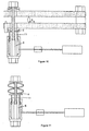
- Figure 10 shows a variant of Figure 1 , in which the rotary tool under test turns a bolt rather than a nut of the threaded nut and bolt assembly.
- the bolt head is a hexagonal head which is engaged by the tool under test.
- Figure 11 shows a corresponding modification of the test joint of Figure 7 .
- the reaction surface 4 against which the variable joint is compressed is the same top annular surface of the piston as in Figures 1 and 7 .
Landscapes
- Physics & Mathematics (AREA)
- General Physics & Mathematics (AREA)
- Engineering & Computer Science (AREA)
- Radar, Positioning & Navigation (AREA)
- Remote Sensing (AREA)
- Testing Of Devices, Machine Parts, Or Other Structures Thereof (AREA)
- Investigating Strength Of Materials By Application Of Mechanical Stress (AREA)
Claims (15)
- Assemblage d'essai à taux de couple variable pour les essais de performance d'outils rotatifs pour des éléments de fixation filetés, comprenant un ensemble à écrou et boulon filetés (1, 2) dans un banc d'essai, l'ensemble étant adapté pour être serré par un outil rotatif en essai pour comprimer un assemblage variable contre une surface de réaction (4) du banc d'essai,
caractérisé en ce que la surface de réaction (4) est une face opérationnelle d'un ensemble à piston et cylindre hydraulique (9, 11), et une commande hydraulique (12, 13) est prévue pour l'ensemble à piston et cylindre (9, 11), incluantdes moyens (13) pour étendre hydrauliquement le piston (11) à partir du cylindre (9) jusqu'à un état étendu qui définit une position d'essai de la surface de réaction (4), etdes moyens (13) pour rétracter hydrauliquement le piston (11) en arrière dans le cylindre (9) pour supprimer la pression sur la surface de réaction (4) à la fin de l'essai, pour faciliter le relâchement de l'assemblage d'essai en vue d'un essai ultérieur. - Assemblage d'essai à taux de couple variable selon la revendication 1, dans lequel la commande hydraulique (12, 13) comprend en outre des moyens (13) pour verrouiller hydrauliquement le piston (11) à son état étendu pendant la durée de l'essai.
- Assemblage d'essai à taux de couple variable selon l'une ou l'autre des revendications précédentes, dans lequel l'ensemble à écrou et boulon comprend un écrou fileté (1) sur une tige filetée (2) qui est montée dans le banc d'essai, l'écrou (1) étant adapté pour être tourné et serré par l'outil en essai.
- Assemblage d'essai à taux de couple variable selon la revendication 3, dans lequel la tige filetée (2) est fixée à une partie d'extrémité d'un organe d'ancrage (6) qui s'étend à travers l'ensemble à piston et cylindre (9, 11) depuis un épaulement de réaction (8) au voisinage d'une extrémité de l'organe d'ancrage (6) qui fournit un siège pour l'ensemble à piston et cylindre (9, 11) jusqu'à ladite partie d'extrémité de l'organe d'ancrage (6) à une extrémité opposée de celui-ci.
- Assemblage d'essai à taux de couple variable selon la revendication 4, dans lequel la tige filetée (2) est fixée à la partie d'extrémité de l'organe d'ancrage (6) en ayant une tête non circulaire (5) de la tige filetée (2) étant retenue dans un évidement coopérant dans ladite partie d'extrémité.
- Assemblage d'essai à taux de couple variable selon la revendication 5, dans lequel la fixation de la tête (5) de la tige filetée (2) est obtenue par une goupille (7) s'étendant latéralement à travers des alésages alignés dans la partie d'extrémité de l'organe d'ancrage (6) et la tête (5) de la tige filetée (2).
- Assemblage d'essai à taux de couple variable selon la revendication 1 ou à revendication 2, dans lequel l'ensemble à écrou et boulon comprend un boulon fileté qui est adapté pour être vissé dans une partie d'extrémité d'un organe d'ancrage fileté (6) qui est monté dans le banc d'essai, le boulon ayant une tête de boulon qui est adaptée pour être tournée par l'outil en essai et l'organe d'ancrage (6) s'étendant à travers l'ensemble à piston et cylindre depuis un épaulement de réaction (4) au voisinage d'une extrémité de l'organe d'ancrage qui fournit un siège pour l'ensemble à piston et cylindre jusqu'à ladite partie d'extrémité de l'organe d'ancrage (6) à une extrémité opposée de celui-ci.
- Assemblage d'essai à taux de couple variable selon l'une quelconque des revendications 4 à 7, comprenant en outre une jauge de contrainte (25) intégrée dans l'organe d'ancrage (6).
- Assemblage d'essai à taux de couple variable selon l'une quelconque des revendications 1 à 8, dans lequel l'assemblage variable est une pile de rondelles Belleville (30) ou un autre matériau compressible.
- Assemblage d'essai à taux de couple variable selon l'une quelconque des revendications 1 à 8, dans lequel l'assemblage variable est une paire de poutres élastiques (14, 15) s'étendant à partir d'un emplacement proximal entre l'ensemble à écrou et boulon (1, 2) et la surface de réaction (4), en porte-à-faux au-dessus d'un organe de pivotement (17) jusqu'à un emplacement distal auquel elles sont fixées ensemble.
- Assemblage d'essai à taux de couple variable selon la revendication 10, dans lequel le taux de couple de l'assemblage variable est variable en déplaçant l'organe de pivotement (17) vers l'axe de vis de l'ensemble à écrou et boulon (1, 2) ou en l'écartant de celui-ci, l'assemblage d'essai comprenant en outre un piston (21) entre les poutres élastiques (14, 15), le piston (21) étant capable d'être actionné pour lever au moins l'une des poutres (14, 15) en l'écartant de l'organe de pivotement (17) pour faciliter le déplacement de l'organe de pivotement (17) vers l'axe de vis ou en l'écartant de celui-ci.
- Assemblage d'essai à taux de couple variable selon la revendication 10 ou la revendication 11, dans lequel un premier ensemble de rondelles angulairement réglable (18) est agencé entre l'ensemble à écrou et boulon (1, 2) et l'une de la paire de poutres élastiques (14, 15), et un second ensemble de rondelles angulairement réglable (18) est agencé entre la surface de réaction (4) du banc d'essai et l'autre de la paire de poutres élastiques (14, 15).
- Assemblage d'essai à taux de couple variable selon la revendication 12, dans lequel chaque ensemble de rondelles angulairement réglable (18) comprend une paire de rondelles dont l'une a une surface partiellement convexe sphérique qui s'appuie contre une surface concave partiellement sphérique correspondante de l'autre, les rondelles de chaque ensemble de rondelles (18) s'adaptant de manière lâche autour de l'ensemble à écrou et boulon (1, 2) pour permettre le glissement de ladite une rondelle de l'ensemble de rondelles par rapport à l'autre.
- Assemblage d'essai à taux de couple variable selon l'une quelconque des revendication 10 à 13, comprenant en outre des moyens pour mesurer la déviation des poutres (14, 15) pour déterminer la force de compression appliquée aux poutres (14, 15).
- Assemblage d'essai à taux de couple variable selon la revendication 14, dans lequel les moyens pour mesurer la déviation des poutres mesurent la rotation angulaire relative de l'écrou (1) et du boulon (2), à partir de quoi une distance parcourue le long d'un pas de la liaison filetée entre l'écrou (1) et le boulon (2) peut être déterminée.
Applications Claiming Priority (2)
| Application Number | Priority Date | Filing Date | Title |
|---|---|---|---|
| GB1001141A GB2467232B (en) | 2010-01-25 | 2010-01-25 | Variable torque-rate test joint |
| PCT/GB2011/000020 WO2011089378A1 (fr) | 2010-01-25 | 2011-01-10 | Assemblage de mesure à taux de couple variable |
Publications (2)
| Publication Number | Publication Date |
|---|---|
| EP2529193A1 EP2529193A1 (fr) | 2012-12-05 |
| EP2529193B1 true EP2529193B1 (fr) | 2014-03-05 |
Family
ID=42045997
Family Applications (1)
| Application Number | Title | Priority Date | Filing Date |
|---|---|---|---|
| EP11700282.4A Active EP2529193B1 (fr) | 2010-01-25 | 2011-01-10 | Assemblage de mesure à taux de couple variable |
Country Status (4)
| Country | Link |
|---|---|
| US (1) | US8720283B2 (fr) |
| EP (1) | EP2529193B1 (fr) |
| GB (1) | GB2467232B (fr) |
| WO (1) | WO2011089378A1 (fr) |
Families Citing this family (5)
| Publication number | Priority date | Publication date | Assignee | Title |
|---|---|---|---|---|
| GB2467232B (en) | 2010-01-25 | 2011-02-23 | Crane Electronics | Variable torque-rate test joint |
| DE102011054964A1 (de) * | 2011-10-31 | 2013-05-02 | Georg Majorosi | Vorrichtung zur vergleichenden Leistungsmessung von Impulsschraubern |
| US20140110138A1 (en) * | 2012-10-23 | 2014-04-24 | David Zarrin | Protective apparatus in connection with machine tools to safeguard workload installation |
| RU2019115113A (ru) * | 2016-10-18 | 2020-11-24 | Сейдж Терапьютикс, Инк. | Оксистеролы и способы их применения |
| CN113567028B (zh) * | 2021-09-01 | 2024-08-02 | 广州市盛华实业有限公司 | 一种多功能涂层性能测试仪 |
Family Cites Families (32)
| Publication number | Priority date | Publication date | Assignee | Title |
|---|---|---|---|---|
| US2503649A (en) | 1945-06-04 | 1950-04-11 | Sylvia V M Zimmerman | Torque tester |
| US3329058A (en) | 1964-04-14 | 1967-07-04 | Cumming James Deans | Tension indicating washer |
| US3815413A (en) | 1973-01-17 | 1974-06-11 | Us Navy | Anemometer wind direction damping system |
| US4127788A (en) | 1977-07-08 | 1978-11-28 | Daugherty Ralph N | Piezoelectric stress indicator for mine roofs |
| US4303001A (en) | 1977-08-18 | 1981-12-01 | Trungold Emanuel H | Bolt tension indicating means |
| US4150559A (en) | 1978-03-20 | 1979-04-24 | Ingersoll-Rand Company | Variable rate test joint |
| JPS6060525A (ja) | 1983-09-14 | 1985-04-08 | Nhk Spring Co Ltd | トルク係数測定装置 |
| DE3560210D1 (en) | 1984-01-31 | 1987-07-09 | Wilmar Eng | Damping rotary motion |
| US4636120A (en) | 1986-06-02 | 1987-01-13 | The Babcock & Wilcox Company | Stud/bolt load gauge |
| SU1496855A1 (ru) | 1987-12-15 | 1989-07-30 | Восточный филиал Института черной металлургии | Устройство дл измерени усилий прокатки |
| JPH01194662A (ja) | 1988-01-29 | 1989-08-04 | Konica Corp | 画像処理装置 |
| RU2042117C1 (ru) | 1992-04-13 | 1995-08-20 | Гридин Николай Иванович | Платформа-дозатор |
| AU4676193A (en) | 1992-07-13 | 1994-01-31 | Sydney L. Terry | Fastener assembly |
| JPH0634464A (ja) | 1992-07-20 | 1994-02-08 | Kobe Steel Ltd | マグネシウム合金のボルトゆるみ試験方法 |
| GB9526333D0 (en) | 1995-12-22 | 1996-02-21 | At & T Global Inf Solution | A displacement measuring device |
| EP0923718B1 (fr) | 1996-09-05 | 2003-11-26 | Crane Electronics Ltd | Joint d'essai simule a rapport de couple variable |
| US6237399B1 (en) | 1998-01-16 | 2001-05-29 | Bellave S. Shivaram | Cantilever having sensor system for independent measurement of force and torque |
| GB9809327D0 (en) * | 1998-05-01 | 1998-07-01 | Crane Electronics | Simulated test joint for impulse tool testing |
| US6609407B1 (en) | 2000-11-06 | 2003-08-26 | Ingersoll-Rand Company | Test apparatus for a wrench used to test previously tightened fasteners |
| JP4087667B2 (ja) | 2002-09-05 | 2008-05-21 | 中央精機株式会社 | ボルト・ナット締結体の締付け力検出方法 |
| US6925395B2 (en) | 2002-10-15 | 2005-08-02 | Canberra Aquila, Inc. | Apparatus and method for measuring the torque applied to bolts |
| SE526961C2 (sv) | 2003-12-19 | 2005-11-29 | Atlas Copco Tools Ab | Anordning för testkörning av motorskruvdragare |
| JP4050255B2 (ja) | 2004-06-25 | 2008-02-20 | アンリツ産機システム株式会社 | X線異物検出装置 |
| US7293466B2 (en) | 2005-07-19 | 2007-11-13 | Hitachi, Ltd. | Bolt with function of measuring strain |
| WO2007038769A1 (fr) * | 2005-09-28 | 2007-04-05 | Hetzel Adrian H | Dispositif electrohydraulique d'etalonnage, de certification et d'analyse de couple par simulation temporisee d'articulation a commande d'angle |
| DE102006020325B4 (de) | 2006-05-03 | 2017-01-19 | Bayerische Motoren Werke Aktiengesellschaft | Vorrichtung zur Ermittlung einer Kennlinie eines Druckaufnehmers |
| DE102006029556B4 (de) | 2006-06-26 | 2013-10-17 | Gtm Gassmann Testing And Metrology Gmbh | Prüfvorrichtung für Impulsschrauber |
| US7428845B1 (en) * | 2006-10-18 | 2008-09-30 | Bobby Collins | Compression gauge |
| GB2438874B (en) | 2007-02-13 | 2008-05-21 | Crane Electronics | Variable torque-rate test joint |
| US7458278B1 (en) * | 2007-10-07 | 2008-12-02 | Pneutech Manufacture Co., Ltd. | Torsion detecting mechanism for a pneumatic tool |
| GB2475322B (en) * | 2009-11-17 | 2012-02-22 | Crane Electronics | Variable torque rate test joint |
| GB2467232B (en) | 2010-01-25 | 2011-02-23 | Crane Electronics | Variable torque-rate test joint |
-
2010
- 2010-01-25 GB GB1001141A patent/GB2467232B/en not_active Expired - Fee Related
-
2011
- 2011-01-10 EP EP11700282.4A patent/EP2529193B1/fr active Active
- 2011-01-10 WO PCT/GB2011/000020 patent/WO2011089378A1/fr not_active Ceased
- 2011-01-10 US US13/574,957 patent/US8720283B2/en active Active
Also Published As
| Publication number | Publication date |
|---|---|
| GB201001141D0 (en) | 2010-03-10 |
| US8720283B2 (en) | 2014-05-13 |
| WO2011089378A1 (fr) | 2011-07-28 |
| GB2467232A (en) | 2010-07-28 |
| GB2467232B (en) | 2011-02-23 |
| EP2529193A1 (fr) | 2012-12-05 |
| US20130036835A1 (en) | 2013-02-14 |
Similar Documents
| Publication | Publication Date | Title |
|---|---|---|
| US8418569B2 (en) | Variable torque-rate test joint | |
| EP2529193B1 (fr) | Assemblage de mesure à taux de couple variable | |
| EP0923718B1 (fr) | Joint d'essai simule a rapport de couple variable | |
| DK2794192T3 (en) | tightening Device | |
| US8261421B2 (en) | Method for setting up and controlling a hydraulic tensioner for applying a preload on one or a plurality of bolts | |
| TWI443334B (zh) | 用於拉伸測試及類似測試的轉動鉗口面 | |
| US8051745B2 (en) | Method and apparatus for tensioning an emergency brake system on a vehicle | |
| US8511181B2 (en) | Variable torque rate test joint | |
| CA2863789C (fr) | Methode, appareil et ecrou pour precharger un palier | |
| US7757586B2 (en) | Device and method for making a screwed connection between a first component and at least one further component | |
| WO2019173994A1 (fr) | Machine d'essai de desserrage de boulons multiples à chargement composite à flexion-traction de bride | |
| US2704472A (en) | Mined torque release means | |
| US7661184B2 (en) | Load applying tool | |
| Meigs et al. | How Accurate Is Torque? Improving the Accuracy of Torque by Leveraging Stud Manufacturers, Tooling, and Practices | |
| CN212586220U (zh) | 一种冰刀检测装置 | |
| KR20240129362A (ko) | 피로시험기의 축 정렬 장치 | |
| EP3063420B1 (fr) | Procédé de protection contre l'usure de contact, outil pour déformer une surface de contact et utilisation de l'outil | |
| PL207631B1 (pl) | Urządzenie do napinania śrub z wyznaczoną siłą poosiową |
Legal Events
| Date | Code | Title | Description |
|---|---|---|---|
| PUAI | Public reference made under article 153(3) epc to a published international application that has entered the european phase |
Free format text: ORIGINAL CODE: 0009012 |
|
| 17P | Request for examination filed |
Effective date: 20120807 |
|
| AK | Designated contracting states |
Kind code of ref document: A1 Designated state(s): AL AT BE BG CH CY CZ DE DK EE ES FI FR GB GR HR HU IE IS IT LI LT LU LV MC MK MT NL NO PL PT RO RS SE SI SK SM TR |
|
| DAX | Request for extension of the european patent (deleted) | ||
| REG | Reference to a national code |
Ref country code: DE Ref legal event code: R079 Ref document number: 602011005267 Country of ref document: DE Free format text: PREVIOUS MAIN CLASS: G01L0005240000 Ipc: G01C0017000000 |
|
| RIC1 | Information provided on ipc code assigned before grant |
Ipc: G01L 25/00 20060101ALI20130704BHEP Ipc: G01L 5/24 20060101ALI20130704BHEP Ipc: G01C 17/00 20060101AFI20130704BHEP |
|
| GRAP | Despatch of communication of intention to grant a patent |
Free format text: ORIGINAL CODE: EPIDOSNIGR1 |
|
| INTG | Intention to grant announced |
Effective date: 20131001 |
|
| GRAS | Grant fee paid |
Free format text: ORIGINAL CODE: EPIDOSNIGR3 |
|
| GRAA | (expected) grant |
Free format text: ORIGINAL CODE: 0009210 |
|
| AK | Designated contracting states |
Kind code of ref document: B1 Designated state(s): AL AT BE BG CH CY CZ DE DK EE ES FI FR GB GR HR HU IE IS IT LI LT LU LV MC MK MT NL NO PL PT RO RS SE SI SK SM TR |
|
| REG | Reference to a national code |
Ref country code: GB Ref legal event code: FG4D |
|
| REG | Reference to a national code |
Ref country code: CH Ref legal event code: EP |
|
| REG | Reference to a national code |
Ref country code: AT Ref legal event code: REF Ref document number: 655180 Country of ref document: AT Kind code of ref document: T Effective date: 20140315 |
|
| REG | Reference to a national code |
Ref country code: IE Ref legal event code: FG4D |
|
| REG | Reference to a national code |
Ref country code: DE Ref legal event code: R096 Ref document number: 602011005267 Country of ref document: DE Effective date: 20140417 |
|
| REG | Reference to a national code |
Ref country code: AT Ref legal event code: MK05 Ref document number: 655180 Country of ref document: AT Kind code of ref document: T Effective date: 20140305 |
|
| REG | Reference to a national code |
Ref country code: NL Ref legal event code: VDEP Effective date: 20140305 |
|
| PG25 | Lapsed in a contracting state [announced via postgrant information from national office to epo] |
Ref country code: NO Free format text: LAPSE BECAUSE OF FAILURE TO SUBMIT A TRANSLATION OF THE DESCRIPTION OR TO PAY THE FEE WITHIN THE PRESCRIBED TIME-LIMIT Effective date: 20140605 Ref country code: LT Free format text: LAPSE BECAUSE OF FAILURE TO SUBMIT A TRANSLATION OF THE DESCRIPTION OR TO PAY THE FEE WITHIN THE PRESCRIBED TIME-LIMIT Effective date: 20140305 |
|
| REG | Reference to a national code |
Ref country code: LT Ref legal event code: MG4D |
|
| PG25 | Lapsed in a contracting state [announced via postgrant information from national office to epo] |
Ref country code: FI Free format text: LAPSE BECAUSE OF FAILURE TO SUBMIT A TRANSLATION OF THE DESCRIPTION OR TO PAY THE FEE WITHIN THE PRESCRIBED TIME-LIMIT Effective date: 20140305 Ref country code: AT Free format text: LAPSE BECAUSE OF FAILURE TO SUBMIT A TRANSLATION OF THE DESCRIPTION OR TO PAY THE FEE WITHIN THE PRESCRIBED TIME-LIMIT Effective date: 20140305 Ref country code: CY Free format text: LAPSE BECAUSE OF FAILURE TO SUBMIT A TRANSLATION OF THE DESCRIPTION OR TO PAY THE FEE WITHIN THE PRESCRIBED TIME-LIMIT Effective date: 20140305 Ref country code: SE Free format text: LAPSE BECAUSE OF FAILURE TO SUBMIT A TRANSLATION OF THE DESCRIPTION OR TO PAY THE FEE WITHIN THE PRESCRIBED TIME-LIMIT Effective date: 20140305 |
|
| PG25 | Lapsed in a contracting state [announced via postgrant information from national office to epo] |
Ref country code: HR Free format text: LAPSE BECAUSE OF FAILURE TO SUBMIT A TRANSLATION OF THE DESCRIPTION OR TO PAY THE FEE WITHIN THE PRESCRIBED TIME-LIMIT Effective date: 20140305 Ref country code: RS Free format text: LAPSE BECAUSE OF FAILURE TO SUBMIT A TRANSLATION OF THE DESCRIPTION OR TO PAY THE FEE WITHIN THE PRESCRIBED TIME-LIMIT Effective date: 20140305 Ref country code: LV Free format text: LAPSE BECAUSE OF FAILURE TO SUBMIT A TRANSLATION OF THE DESCRIPTION OR TO PAY THE FEE WITHIN THE PRESCRIBED TIME-LIMIT Effective date: 20140305 |
|
| PG25 | Lapsed in a contracting state [announced via postgrant information from national office to epo] |
Ref country code: IS Free format text: LAPSE BECAUSE OF FAILURE TO SUBMIT A TRANSLATION OF THE DESCRIPTION OR TO PAY THE FEE WITHIN THE PRESCRIBED TIME-LIMIT Effective date: 20140705 Ref country code: EE Free format text: LAPSE BECAUSE OF FAILURE TO SUBMIT A TRANSLATION OF THE DESCRIPTION OR TO PAY THE FEE WITHIN THE PRESCRIBED TIME-LIMIT Effective date: 20140305 Ref country code: RO Free format text: LAPSE BECAUSE OF FAILURE TO SUBMIT A TRANSLATION OF THE DESCRIPTION OR TO PAY THE FEE WITHIN THE PRESCRIBED TIME-LIMIT Effective date: 20140305 Ref country code: BG Free format text: LAPSE BECAUSE OF FAILURE TO SUBMIT A TRANSLATION OF THE DESCRIPTION OR TO PAY THE FEE WITHIN THE PRESCRIBED TIME-LIMIT Effective date: 20140605 Ref country code: BE Free format text: LAPSE BECAUSE OF FAILURE TO SUBMIT A TRANSLATION OF THE DESCRIPTION OR TO PAY THE FEE WITHIN THE PRESCRIBED TIME-LIMIT Effective date: 20140305 Ref country code: NL Free format text: LAPSE BECAUSE OF FAILURE TO SUBMIT A TRANSLATION OF THE DESCRIPTION OR TO PAY THE FEE WITHIN THE PRESCRIBED TIME-LIMIT Effective date: 20140305 Ref country code: CZ Free format text: LAPSE BECAUSE OF FAILURE TO SUBMIT A TRANSLATION OF THE DESCRIPTION OR TO PAY THE FEE WITHIN THE PRESCRIBED TIME-LIMIT Effective date: 20140305 |
|
| PG25 | Lapsed in a contracting state [announced via postgrant information from national office to epo] |
Ref country code: SK Free format text: LAPSE BECAUSE OF FAILURE TO SUBMIT A TRANSLATION OF THE DESCRIPTION OR TO PAY THE FEE WITHIN THE PRESCRIBED TIME-LIMIT Effective date: 20140305 Ref country code: ES Free format text: LAPSE BECAUSE OF FAILURE TO SUBMIT A TRANSLATION OF THE DESCRIPTION OR TO PAY THE FEE WITHIN THE PRESCRIBED TIME-LIMIT Effective date: 20140305 Ref country code: PL Free format text: LAPSE BECAUSE OF FAILURE TO SUBMIT A TRANSLATION OF THE DESCRIPTION OR TO PAY THE FEE WITHIN THE PRESCRIBED TIME-LIMIT Effective date: 20140305 |
|
| REG | Reference to a national code |
Ref country code: DE Ref legal event code: R097 Ref document number: 602011005267 Country of ref document: DE |
|
| PG25 | Lapsed in a contracting state [announced via postgrant information from national office to epo] |
Ref country code: PT Free format text: LAPSE BECAUSE OF FAILURE TO SUBMIT A TRANSLATION OF THE DESCRIPTION OR TO PAY THE FEE WITHIN THE PRESCRIBED TIME-LIMIT Effective date: 20140707 |
|
| PLBE | No opposition filed within time limit |
Free format text: ORIGINAL CODE: 0009261 |
|
| STAA | Information on the status of an ep patent application or granted ep patent |
Free format text: STATUS: NO OPPOSITION FILED WITHIN TIME LIMIT |
|
| PG25 | Lapsed in a contracting state [announced via postgrant information from national office to epo] |
Ref country code: DK Free format text: LAPSE BECAUSE OF FAILURE TO SUBMIT A TRANSLATION OF THE DESCRIPTION OR TO PAY THE FEE WITHIN THE PRESCRIBED TIME-LIMIT Effective date: 20140305 |
|
| 26N | No opposition filed |
Effective date: 20141208 |
|
| REG | Reference to a national code |
Ref country code: DE Ref legal event code: R097 Ref document number: 602011005267 Country of ref document: DE Effective date: 20141208 |
|
| PG25 | Lapsed in a contracting state [announced via postgrant information from national office to epo] |
Ref country code: IT Free format text: LAPSE BECAUSE OF FAILURE TO SUBMIT A TRANSLATION OF THE DESCRIPTION OR TO PAY THE FEE WITHIN THE PRESCRIBED TIME-LIMIT Effective date: 20140305 |
|
| PG25 | Lapsed in a contracting state [announced via postgrant information from national office to epo] |
Ref country code: SI Free format text: LAPSE BECAUSE OF FAILURE TO SUBMIT A TRANSLATION OF THE DESCRIPTION OR TO PAY THE FEE WITHIN THE PRESCRIBED TIME-LIMIT Effective date: 20140305 |
|
| REG | Reference to a national code |
Ref country code: CH Ref legal event code: PL |
|
| PG25 | Lapsed in a contracting state [announced via postgrant information from national office to epo] |
Ref country code: LU Free format text: LAPSE BECAUSE OF FAILURE TO SUBMIT A TRANSLATION OF THE DESCRIPTION OR TO PAY THE FEE WITHIN THE PRESCRIBED TIME-LIMIT Effective date: 20150110 |
|
| PG25 | Lapsed in a contracting state [announced via postgrant information from national office to epo] |
Ref country code: MC Free format text: LAPSE BECAUSE OF FAILURE TO SUBMIT A TRANSLATION OF THE DESCRIPTION OR TO PAY THE FEE WITHIN THE PRESCRIBED TIME-LIMIT Effective date: 20140305 |
|
| PG25 | Lapsed in a contracting state [announced via postgrant information from national office to epo] |
Ref country code: LI Free format text: LAPSE BECAUSE OF NON-PAYMENT OF DUE FEES Effective date: 20150131 Ref country code: CH Free format text: LAPSE BECAUSE OF NON-PAYMENT OF DUE FEES Effective date: 20150131 |
|
| REG | Reference to a national code |
Ref country code: IE Ref legal event code: MM4A |
|
| REG | Reference to a national code |
Ref country code: FR Ref legal event code: PLFP Year of fee payment: 6 |
|
| PG25 | Lapsed in a contracting state [announced via postgrant information from national office to epo] |
Ref country code: IE Free format text: LAPSE BECAUSE OF NON-PAYMENT OF DUE FEES Effective date: 20150110 |
|
| PG25 | Lapsed in a contracting state [announced via postgrant information from national office to epo] |
Ref country code: GR Free format text: LAPSE BECAUSE OF FAILURE TO SUBMIT A TRANSLATION OF THE DESCRIPTION OR TO PAY THE FEE WITHIN THE PRESCRIBED TIME-LIMIT Effective date: 20140606 |
|
| PG25 | Lapsed in a contracting state [announced via postgrant information from national office to epo] |
Ref country code: MT Free format text: LAPSE BECAUSE OF FAILURE TO SUBMIT A TRANSLATION OF THE DESCRIPTION OR TO PAY THE FEE WITHIN THE PRESCRIBED TIME-LIMIT Effective date: 20140305 |
|
| REG | Reference to a national code |
Ref country code: FR Ref legal event code: PLFP Year of fee payment: 7 |
|
| PG25 | Lapsed in a contracting state [announced via postgrant information from national office to epo] |
Ref country code: HU Free format text: LAPSE BECAUSE OF FAILURE TO SUBMIT A TRANSLATION OF THE DESCRIPTION OR TO PAY THE FEE WITHIN THE PRESCRIBED TIME-LIMIT; INVALID AB INITIO Effective date: 20110110 Ref country code: SM Free format text: LAPSE BECAUSE OF FAILURE TO SUBMIT A TRANSLATION OF THE DESCRIPTION OR TO PAY THE FEE WITHIN THE PRESCRIBED TIME-LIMIT Effective date: 20140305 |
|
| PG25 | Lapsed in a contracting state [announced via postgrant information from national office to epo] |
Ref country code: TR Free format text: LAPSE BECAUSE OF FAILURE TO SUBMIT A TRANSLATION OF THE DESCRIPTION OR TO PAY THE FEE WITHIN THE PRESCRIBED TIME-LIMIT Effective date: 20140305 |
|
| REG | Reference to a national code |
Ref country code: FR Ref legal event code: PLFP Year of fee payment: 8 |
|
| PG25 | Lapsed in a contracting state [announced via postgrant information from national office to epo] |
Ref country code: MK Free format text: LAPSE BECAUSE OF FAILURE TO SUBMIT A TRANSLATION OF THE DESCRIPTION OR TO PAY THE FEE WITHIN THE PRESCRIBED TIME-LIMIT Effective date: 20140305 |
|
| PG25 | Lapsed in a contracting state [announced via postgrant information from national office to epo] |
Ref country code: AL Free format text: LAPSE BECAUSE OF FAILURE TO SUBMIT A TRANSLATION OF THE DESCRIPTION OR TO PAY THE FEE WITHIN THE PRESCRIBED TIME-LIMIT Effective date: 20140305 |
|
| P01 | Opt-out of the competence of the unified patent court (upc) registered |
Effective date: 20230509 |
|
| PGFP | Annual fee paid to national office [announced via postgrant information from national office to epo] |
Ref country code: GB Payment date: 20251201 Year of fee payment: 16 |
|
| PGFP | Annual fee paid to national office [announced via postgrant information from national office to epo] |
Ref country code: DE Payment date: 20260122 Year of fee payment: 16 |
|
| PGFP | Annual fee paid to national office [announced via postgrant information from national office to epo] |
Ref country code: FR Payment date: 20260120 Year of fee payment: 16 |