EP2529455B1 - Prévention des dommages aux câbles sous-marins et éléments similaires pendant leur pose ou leur récupération - Google Patents
Prévention des dommages aux câbles sous-marins et éléments similaires pendant leur pose ou leur récupération Download PDFInfo
- Publication number
- EP2529455B1 EP2529455B1 EP10843794.8A EP10843794A EP2529455B1 EP 2529455 B1 EP2529455 B1 EP 2529455B1 EP 10843794 A EP10843794 A EP 10843794A EP 2529455 B1 EP2529455 B1 EP 2529455B1
- Authority
- EP
- European Patent Office
- Prior art keywords
- sheaves
- support frame
- accessory
- rotary
- support structure
- Prior art date
- Legal status (The legal status is an assumption and is not a legal conclusion. Google has not performed a legal analysis and makes no representation as to the accuracy of the status listed.)
- Active
Links
Images



Classifications
-
- F—MECHANICAL ENGINEERING; LIGHTING; HEATING; WEAPONS; BLASTING
- F16—ENGINEERING ELEMENTS AND UNITS; GENERAL MEASURES FOR PRODUCING AND MAINTAINING EFFECTIVE FUNCTIONING OF MACHINES OR INSTALLATIONS; THERMAL INSULATION IN GENERAL
- F16L—PIPES; JOINTS OR FITTINGS FOR PIPES; SUPPORTS FOR PIPES, CABLES OR PROTECTIVE TUBING; MEANS FOR THERMAL INSULATION IN GENERAL
- F16L1/00—Laying or reclaiming pipes; Repairing or joining pipes on or under water
- F16L1/12—Laying or reclaiming pipes on or under water
- F16L1/16—Laying or reclaiming pipes on or under water on the bottom
-
- B—PERFORMING OPERATIONS; TRANSPORTING
- B63—SHIPS OR OTHER WATERBORNE VESSELS; RELATED EQUIPMENT
- B63B—SHIPS OR OTHER WATERBORNE VESSELS; EQUIPMENT FOR SHIPPING
- B63B35/00—Vessels or similar floating structures specially adapted for specific purposes and not otherwise provided for
- B63B35/04—Cable-laying vessels
-
- B—PERFORMING OPERATIONS; TRANSPORTING
- B66—HOISTING; LIFTING; HAULING
- B66D—CAPSTANS; WINCHES; TACKLES, e.g. PULLEY BLOCKS; HOISTS
- B66D1/00—Rope, cable, or chain winding mechanisms; Capstans
- B66D1/60—Rope, cable, or chain winding mechanisms; Capstans adapted for special purposes
- B66D1/74—Capstans
- B66D1/7405—Capstans having two or more drums providing tractive force
-
- B—PERFORMING OPERATIONS; TRANSPORTING
- B66—HOISTING; LIFTING; HAULING
- B66D—CAPSTANS; WINCHES; TACKLES, e.g. PULLEY BLOCKS; HOISTS
- B66D1/00—Rope, cable, or chain winding mechanisms; Capstans
- B66D1/60—Rope, cable, or chain winding mechanisms; Capstans adapted for special purposes
- B66D1/74—Capstans
- B66D1/7415—Friction drives, e.g. pulleys, having a cable winding angle of less than 360 degrees
-
- F—MECHANICAL ENGINEERING; LIGHTING; HEATING; WEAPONS; BLASTING
- F16—ENGINEERING ELEMENTS AND UNITS; GENERAL MEASURES FOR PRODUCING AND MAINTAINING EFFECTIVE FUNCTIONING OF MACHINES OR INSTALLATIONS; THERMAL INSULATION IN GENERAL
- F16L—PIPES; JOINTS OR FITTINGS FOR PIPES; SUPPORTS FOR PIPES, CABLES OR PROTECTIVE TUBING; MEANS FOR THERMAL INSULATION IN GENERAL
- F16L1/00—Laying or reclaiming pipes; Repairing or joining pipes on or under water
- F16L1/12—Laying or reclaiming pipes on or under water
- F16L1/20—Accessories therefor, e.g. floats or weights
- F16L1/202—Accessories therefor, e.g. floats or weights fixed on or to vessels
-
- F—MECHANICAL ENGINEERING; LIGHTING; HEATING; WEAPONS; BLASTING
- F16—ENGINEERING ELEMENTS AND UNITS; GENERAL MEASURES FOR PRODUCING AND MAINTAINING EFFECTIVE FUNCTIONING OF MACHINES OR INSTALLATIONS; THERMAL INSULATION IN GENERAL
- F16L—PIPES; JOINTS OR FITTINGS FOR PIPES; SUPPORTS FOR PIPES, CABLES OR PROTECTIVE TUBING; MEANS FOR THERMAL INSULATION IN GENERAL
- F16L1/00—Laying or reclaiming pipes; Repairing or joining pipes on or under water
- F16L1/12—Laying or reclaiming pipes on or under water
- F16L1/20—Accessories therefor, e.g. floats or weights
- F16L1/235—Apparatus for controlling the pipe during laying
-
- H—ELECTRICITY
- H02—GENERATION; CONVERSION OR DISTRIBUTION OF ELECTRIC POWER
- H02G—INSTALLATION OF ELECTRIC CABLES OR LINES, OR OF COMBINED OPTICAL AND ELECTRIC CABLES OR LINES
- H02G1/00—Methods or apparatus specially adapted for installing, maintaining, repairing or dismantling electric cables or lines
- H02G1/06—Methods or apparatus specially adapted for installing, maintaining, repairing or dismantling electric cables or lines for laying cables, e.g. laying apparatus on vehicle
- H02G1/10—Methods or apparatus specially adapted for installing, maintaining, repairing or dismantling electric cables or lines for laying cables, e.g. laying apparatus on vehicle in or under water
Definitions
- the present invention relates to a method of preventing damage in an elongate flexible element having an accessory integral with the element and forming therewith a section that risks being damaged on passing from a generally horizontal/vertical orientation to a generally vertical/horizontal one during subsea laying or retrieving of the element.
- the invention also relates to a support structure for an elongate flexible element having an accessory integral with the element and forming therewith a section that risks being damaged on passing from a generally horizontal/vertical orientation to a generally vertical/horizontal one during subsea laying or retrieving of the element.
- element as used herein is intended to encompass subsea elements such as seabed pipes and cables, such as seismic cables, for example, which have sensor modules distributed rather densely along the cable.
- sensor modules form an example of an accessory that is integral with the elongate flexible element, but the accessories are not restricted to such sensor modules.
- the general concept for deployment is either a linear traction unit or a winch.
- cable from a cable storage is fed by a traction unit over an overboard unit, where the cable changes direction from horizontal to vertical.
- the traction unit may comprise a series of driven wheel or belt nips, and the overboard unit may be a simple wheel that changes the feed direction of the cable.
- the cable is stored on a winch, from which it is spooled out by a drive motor.
- the cable can either be spooled out from a winch or drum, or it can be supplied from a storage container or a rotary table (carousel).
- a winch or drum For short and/or thin cables the winch alternative is often used, but for lager cables this is normally not a good solution.
- a rotary table For big power cables and long telecom cables it is common practice to store the cable on a "carousel”.
- the cable tension can be controlled by a linear traction machine or a capstan, or if the cable is deployed from a winch, the winch could be used to control the tension and hold back the cable.
- the traction machines are often based on wheels or belts squeezing on the outside of the cable. This can be a problem if the cable is of a fragile design, or contains fragile components such as sensor modules or connectors. Also if the cable is deployed from a winch, and the tension is high, there can be damages to a fragile cable or module.
- US 4,714,380 discloses various mechanisms for lifting an elongate flexible element, which has an accessory that is integral with the element and forms therewith a stiff section, up from the periphery of the direction changing wheel in order to increase the bend radius.
- a conventional device for linear traction of the element e.g. opposed caterpillar tracks, is controlled to avoid tension in the element between the traction device and the lifting mechanism, so that a bend in the element, where the element exits the accessory, will be smooth.
- EP0499106 there is described a method and an apparatus for paying out or hauling in the supply line of an underwater cable device.
- this equipment is not suitable for continuous deployment/retrieval of heavy cable and deep water where the tension in the cable can be several tons.
- the object of the present invention is to eliminate the risk of damaging the elongate flexible element and/or its integrated accessory on passage thereof over a direction changing support structure.
- a support structure of the kind referred to in the second paragraph above comprises at least four rotary sheaves and a rotary support frame for carrying the sheaves, said sheaves being equidistantly spaced from the rotational axis of the rotary frame and equiangularly spaced from one another, said at least four sheaves being spaced from each other a distance that is greater than a length of the accessory to permit the element with the integral accessory to extend in a straight line between the two of the four sheaves, each sheave having a rotational axis that is substantially parallel to a rotational axis of the support frame, and the support frame being rotary at least between a position in which the accessory with associated ends of the element is located in a generally horizontal orientation and is supported by said sheaves and a position in which the accessory with associated ends of the element is located in a generally vertical orientation during continuous support by said sheaves.
- both the method and the support structure of the present invention make it possible to change the orientation of the accessory and adjacent sections of the element from generally horizontal to generally vertical, when laying an elongate flexible subsea element or from generally vertical to generally horizontal when retrieving the element, without exposing the accessory and adjacent sections of the element to damaging bends.
- the term "sheave” is used to designate a wheel or roller with a groove along its edge for guiding a cable or similar elongate flexible element while changing the running direction of the cable or other element.
- the support structure advantageously comprises more than two rotary sheaves, preferably four sheaves, that are carried by the rotary support frame, and the sheaves are equidistantly spaced from the rotational axis of the rotary frame and equiangularly spaced from one another.
- the sheaves are located at the corners of a square.
- the support structure is part of an overboard unit.
- the sheaves have a circumferential groove fitting the element that engages the sheave, the sheaves and the support frame can rotate freely, a tensioning unit is provided upstream of the support structure to keep a desired tension in the element, and a locking system is provided for preventing the support frame to rotate when it should not.
- arcuate rows of wheels provided with circumferential grooves may be substituted for large diameter sheaves.
- the support structure is part of a combined overboard unit and traction unit.
- the sheaves have a circumferential groove giving place for more than one single element to engage the sheave, and the support frame and all of the sheaves are motor driven, the support frame and all of the sheaves each have a separate motor, and the motors are individually controlled.
- the element carried by the sheaves is wrapped around the support frame one or more times.
- a guiding system for the element is provided on the circumference of the sheaves for moving the element from one side of the support frame to the other as the sheaves rotate, so as to prevent the element from getting tangled up at one side of the support frame.
- Fig. 1 is a schematic side view of a ship 1 for laying and retrieving an elongate flexible subsea element 2 with integrated accessories 3 .
- the elongate flexible subsea element may be a seabed pipe or a cable, such as a seismic cable, for example, which has sensor modules distributed rather densely along the cable.
- sensor modules form an example of an accessory that is integral with the elongate flexible element, but the accessories are not restricted to such sensor modules.
- Another example is a connector.
- the cable 2 or other elongate flexible element is supplied from a supply device 4, which includes either a storage container or a rotary table (carousel), or alternatively a winch or drum.
- a supply device 4 which includes either a storage container or a rotary table (carousel), or alternatively a winch or drum.
- the winch alternative is often used, but for thick cables this is normally not a good solution.
- the supply device 4 also includes either a linear traction unit or a winch.
- a linear traction unit In the first case, cable from the cable storage is fed by the traction unit over a support structure 5, where the cable changes direction from horizontal to vertical.
- the traction unit may comprise a series of driven wheel nips or belt nips, while in the second case the cable is stored on a winch, from which it is spooled out by a drive motor.
- the traction machines are often based on wheels or belts squeezing on the outside of the cable. This can be a problem if the cable is of a fragile design, or contains fragile components such as sensor modules or connectors.
- Fig. 2 is a side view on an enlarged scale of the support structure 5 shown in Fig. 1 , where it is an overboard unit.
- it comprises at least two rotary sheaves 6 and a rotary support frame 7 for carrying the sheaves.
- the at least two sheaves are spaced from each other a distance that is greater than a length of the accessory 3 to permit the element 2 with the integral accessory to extend in a straight line between the two sheaves 6, and each sheave has a rotational axis 6' that is parallel to a rotational axis 7' of the support frame 7.
- a bracket 8 is mounted to the stern of the ship 1 for carrying the rotary support frame 7.
- the sheaves 6 have an effective radius of curvature that is larger than the minimum permissible bend radius of the element 2.
- the support frame 7 is rotary at least between a first position in which the accessory 3 with associated ends of the element 2 has a generally horizontal orientation and is supported by the at least two sheaves 6, and a second position in which the accessory 3 with associated ends of the element 2 has a generally vertical orientation. During the rotation of the support frame 7, the accessory 3 does not move in relation to the at least two sheaves and it is continuously supported by the sheaves 6.
- the support frame 7 may be a straight arm.
- the two sheaves 6 are located at the ends of the arm, and the arm can rotate around its center.
- the bracket 8 has to project rearward from the stern of the ship 1 to permit to permit the arm to rotate a quarter of a full turn from a generally horizontal orientation to a generally vertical one, or the other way around.
- the arm swings back to its original position for receiving the next stiff section and repeating the action.
- the arm may be angular, and the two halves of the arm may form a straight angle, for example, between them.
- two identical arms having rotary sheaves at their ends may cross each other perpendicularly to form a substantially square rotary support frame having the sheaves located in the corners of the square.
- the two arms may have to be interconnected by struts.
- FIG. 2 A preferred embodiment of a support frame 7 having four sheaves 6 located at the corners of a square is shown in Fig. 2 .
- the support frame 7 has four spokes 9 extending between a hub 10 and a surrounding generally square frame 11.
- the very corners of the square are beveled to give the support frame 7 an octagonal shape, and the four rotary sheaves 6 are mounted at the beveled corners.
- the sheaves 6 are, according to the invention, equidistantly spaced from the rotational axis of the rotary frame 7 and equiangularly spaced from one another.
- Fig. 3 is an end view of the support structure of Fig. 2 .
- the sheaves 6 are provided with a circumferential groove 12 fitting the element 2 that engages the sheave.
- the rotary support frame 7 is mounted in bearings 13 carried by a forked end of the bracket 8.
- the support frame 7 can rotate around its own center, and the sheaves 6 at the corners of the frame can rotate freely. There is also a locking system keeping the support frame 7 from rotating when it should not. It can be made as a pure mechanical device, or it can be an electrical or hydraulic system. This system will require a traction unit to hold the cable tension. This is not shown in the figure, but it could be a conventional linear traction unit or a capstan, placed in front of the overboard unit. A mechanical locking system will be described in the following in connection with Figs 5-10 .
- Figs. 4a to 4d is a sequence of side views of the overboard unit in operation, with the flexible element 2 passing the support structure 5 of Fig. 2 .
- the element 2 passes over the overboard unit as shown in Fig. 4a .
- the element 2 rolls over the upper left sheave 6, and the support frame 7 is kept from rotating by the locking system. Only the friction force in the sheave 6 will try to rotate the support frame 7, all other forces are balanced, and the force needed to keep the support frame 7 from rotating is small.
- a stiff module or other accessory 3 When a stiff module or other accessory 3 reaches the overboard unit, it will get to a position halfway between the two upper sheaves 6, as shown in Fig. 4b . At this point the locking system is released, and the support frame 7 can rotate freely with no relative movement between the element 2 and the support frame 7. Additional functions, not shown, can lock the accessory 3 to the support frame 7 to avoid slippage. The result will be that the support frame 7 rotates with the element 2, and the stiff module or other accessory 3 is protected from any bending forces as shown in Fig. 4c .
- FIG. 5 to 10 An alternative preferred embodiment of the support structure of the present invention is shown in Figs. 5 to 10 .
- the support structure 5 in the embodiment of Figs. 2-4 will be referred to as support structure 105 in the embodiment of Figs. 5-10 .
- Fig. 5 is a side view of the support structure 105 of Fig. 1 of an overboard unit, and it comprises a generally square support frame 107 and four rotary sheaves 106, one at each corner of the square.
- the rotary sheaves here are roller-shaped and preceded by and followed by additional roller-shaped sheaves 106, which together form an arcuate path for the element 102, which path has a radius of curvature that is of the same size as the radius of a single sheave of larger diameter carried by the rotary support frame 107 would have, if provided.
- the arcuate path formed by the roller-shaped sheaves 106 is identical to the circle arc of a 90 degree sector of a sheave 6 in the embodiment of Figs. 2-4 .
- the preferred shape of the roller-shaped sheaves 106 is best shown in Fig. 6 .
- the support structure 105 is provided with a system for locking the support frame 107 in various desired positions.
- Many rotation preventing systems, mechanical or not, are conceivable for a skilled art worker, but in the embodiment shown in Figs. 5-10 , the rotation locking system is generally designated 114 and comprises four sets of a two-armed pivotal hook 115, a push-rod 116, a spring 117, and a central non-rotary cam wheel 118 common to all sets.
- the pivotal hook 115 has two ends, one of which is shaped for engagement with a forward end of the arriving generally horizontal integral accessory 103.
- the push rod 116 has one end pivotally connected to the other end of the hook 115 and extends from there toward the rotational axis of the support frame 107.
- the cam wheel 118 has a cam surface including four equidistantly and equiangularly spaced cam tops and intermediate valleys and is coaxial with the support frame 107 but is fixed and does not rotate.
- the spring 117 is either a compression spring or a tension spring, and it is arranged to press the other end of the push-rod 116 against the cam surface provided on the cam wheel 118.
- two identical cam wheels 118 are used, one on each side of the support frame 107 but not connected thereto, and the push rod 116 has a T-shaped end 121 (best shown in Figs. 6 and 8 ) that engages the cam surfaces on both of the cam wheels 118.
- the spring 117 is surrounded by a housing 119 (best shown in Fig. 10 ) standing on a support member 120 extending at a substantially right angle to the push rod 116 and from one spoke 109 to another.
- a housing 119 best shown in Fig. 10
- the support frame 107 is shown in a first locked position, and a forward end of a just arrived horizontal accessory 103 is stopped by the hook 115 as is best shown in Fig. 9 .
- the push rod 116 goes from a cam top to an adjacent valley and thereby swings the hook 115 out of locking engagement with forward end of the accessory 103.
- a reason for the locking effect is that the friction in the bearings of the roller-shaped sheaves during deployment of a cable or other elongate flexible element is smaller than the combined friction of the support frame bearings and of the push rods that move axially and slide on the cam wheels.
- a different alternative can be an electrically operated locking system, not shown. This will have an electric sensor, which detects when an integral accessory 103 gets into the support frame 107 and then releases an electrically operated lock. When the support frame 107 has rotated 90 degrees, other detectors will sense this and turn the lock on again.
- FIG. 11 to 15 An alternative preferred embodiment of the support structure of the present invention is shown in Figs. 11 to 15 .
- the support structure 5 in the embodiment of Figs. 2-4 will be referred to as support structure 205 in the embodiment of Figs. 11-15 .
- Fig. 11 is a side view of the support structure 205 of Fig. 1 of a combined overboard unit and traction unit, and it comprises a support frame 207 and rotary sheaves 206
- Fig. 12 is an end view of the support structure of Fig. 11 .
- a first difference is that every one of the four sheaves 206 is equipped with a motor 226 for driving it. Also the support frame 207 itself is rotated by a motor 227.
- the profile of the sheaves 206 is also different, in that the circumferential groove 212 has a flat bottom and gives room for more than one single element 202 to pass the sheave 206 .
- a guiding system for moving the element 202 in the grooves 212 of the sheaves 206 from one side to the other of the support frame 207 as the sheaves 206 rotate, so as to permit the element 202 to extend more than one full turn around the support frame 207 while preventing the element 202 from getting tangled up at one side of the support frame 207.
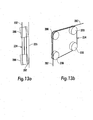
- Various guiding systems may be used, but a simple one, generally designated 224, is schematically shown in Figs. 13a and 13b . As shown in the top view of Fig.
- the rotary sheaves 206 are located in such a manner that their rotational axes are parallel to one another but form an angle close to but deviating from 90 degrees with a vertical plane 225 through identically located points of the four sheaves 206 in the combined overboard and traction unit.
- the vertical plane 225 is parallel to the rotational plane of the support frame 207. Every time the elongate flexible element 202 bends over anyone of the sheaves 206, it is moved sideways.
- the skew is exaggerated for illustration purposes.
- the motors 226 and 227 that are used to control the sheaves 206 and the support frame 207 will typically be electric motors with individual control system for each.
- the control system will control the rotational speed and tension of the sheaves 206 and the support frame 207.
- a slip ring may be included in the support frame 207.
- a common AC power is supplied over the slip rings to the four motors 226, whereas the last motor 227 may be powered directly, without going through the slip ring.
- Figs. 14a to 14d is a sequence of side views of the combined overboard and traction unit in operation, with the flexible element 202 passing the support structure 205 of Fig. 11
- the flexible element 202 is wrapped around the support frame 207 one or more times. In a situation when only the flexible element 202 is deployed, this is done by breaking the support frame 207 to hold it still and simultaneously rotating the sheaves 206. By controlling the tension on each sheave 206, the load is distributed to multiple points on the flexible element 202, and by that the flexible element 202 is less exposed to damage.
- the method and the support structure of the present invention are applicable to eliminate the risk of damaging an elongate flexible element and/or an accessory integrated therein, such as a seismic cable having sensor modules distributed rather densely along the cable and forming therewith stiff sections that risk being damaged, on passing from a generally horizontal/vertical orientation to a generally vertical/horizontal one during subsea laying or retrieving of the cable.
Landscapes
- Engineering & Computer Science (AREA)
- Mechanical Engineering (AREA)
- General Engineering & Computer Science (AREA)
- Chemical & Material Sciences (AREA)
- Combustion & Propulsion (AREA)
- Ocean & Marine Engineering (AREA)
- Laying Of Electric Cables Or Lines Outside (AREA)
- Pulleys (AREA)
Claims (13)
- Un procédé pour empêcher des dommages à un élément souple allongé (2 ; 102 ; 202) comportant un accessoire (3 ; 103 ; 203) solidaire de l'élément et formant avec celui-ci une portion qui risque d'être endommagée lors du passage d'une orientation généralement horizontale / verticale à une orientation généralement verticale / horizontale pendant la pose sous-marine ou la récupération sous-marine de l'élément (2 ; 102 ; 202), caractérisé par :a) le fait d'utiliser d'une structure de support (5 ; 105 ; 205) comprenant au moins quatre poulies rotatives (6 ; 106 ; 206) et un châssis de support rotatif (7 ; 107 ; 207) pour supporter les poulies, avec un espacement équidistant desdites poulies (6 ; 106 ; 206) par rapport à l'axe du châssis tournant (7 ; 107 ; 207) et disposées selon des angles égaux les unes des autres, lesdites au moins quatre poulies (6 ; 106 ; 206) étant espacées les unes des autre d'une distance qui est supérieure à une longueur de l'accessoire (3 ; 103 ; 203) pour permettre à l'élément (2 ; 102 ; 202) avec l'accessoire (3 ; 103 ; 203) solidaire de lui de s'étendre en ligne droite entre deux des quatre poulies (6 ; 106 ; 206), chaque poulie (6 ; 106 ; 206) ayant un axe de rotation (6' ; 206') qui est sensiblement parallèle à un axe de rotation (7' ; 207') du châssis de support (7 ; 107 ; 207),b) le fait d'introduire de l'élément (2 ; 102 ; 202) dans une position dans laquelle il est porté par deux desdites au moins quatre poulies (6 ; 106 ; 206) et dans laquelle l'accessoire (3 ; 103 ; 203) solidaire est situé entre deux desdites quatre poulies (6 ; 106 ; 206) ;c) le fait de faire tourner le châssis de support (7 ; 107 ; 207) sur le quart d'un tour complet de manière que l'accessoire (3 ; 103 ; 203) passe d'une orientation généralement verticale / horizontale à une orientation généralement horizontale / verticale, tout en maintenant l'emplacement de l'accessoire (3 ; 103 ; 203) entre les poulies (6 ; 106 ; 206) ; etd) le fait de poursuivre l'alimentation de l'élément (2 ; 102 ; 202) pour permettre à l'accessoire (3 ; 103 ; 203) de quitter la position entre les poulies (6 ; 106 ; 206), de sorte que l'accessoire (3 ; 103 ; 203) et les portions adjacentes de l'élément (2 ; 102 ; 202) ont changé leur orientation d'un quart de tour complet sans avoir été exposées à des courbures dommageables.
- Un procédé selon la revendication 1, caractérisé par le fait de prévoir les poulies (6 ; 106) avec une gorge circonférentielle (12 ; 112) recevant de façon ajustée l'élément (2 ; 102) qui s'engage sur la poulie (6 ; 106).
- Un procédé selon la revendication 2, caractérisé par le fait de monter les poulies (6 ; 106) et le châssis de support (7 ; 107) de telle sorte qu'ils tournent librement, et de prévoir une unité (4) mise en tension pour maintenir une tension désirée dans l'élément (2 ; 102), de préférence en prévoyant un système de verrouillage (114) pour empêcher le châssis de support (7 ; 107) de tourner lorsqu'il ne doit pas tourner.
- Un procédé selon l'une quelconque des revendications 2 ou 3, caractérisé en ce que lesdites poulies (106) sont en forme de galet et sont précédées et suivies par des poulies supplémentaires (106) en forme de galet, qui forment conjointement un trajet en forme d'arc pour l'élément (102), ledit trajet ayant un rayon de courbure qui est de la même taille que le rayon qu'aurait une seule poulie (6) de plus grand diamètre portée par le châssis de support rotatif (107).
- Un procédé selon la revendication 1, caractérisé par le fait de prévoir les poulies (206) avec une gorge circonférentielle (212) ayant de la place qui permet à plus d'un seul élément (202) de s'engager sur la poulie (206), et de prévoir des moteurs (227 et 226, respectivement) pour l'entraînement du châssis de support (207) et de toutes les poulies (206), de préférence en prévoyant un moteur séparé (227 et 226, respectivement) pour le châssis de support (207) et chacune des poulies (206), et de manière davantage préférée en commandant les moteurs (227, 226) individuellement.
- Un procédé selon l'une quelconque des revendications 4 ou 5, caractérisé par le fait de prévoir un système de guidage (224) pour déplacer l'élément (202) sur la circonférence des poulies (206) depuis un côté du châssis de support (207) vers l'autre côté lorsque les poulies (206) tournent, de manière à permettre à l'élément (202) de s'étendre sur plus d'un tour complet autour du châssis de support (207) tout en empêchant l'élément (202) de s'emmêler sur un côté du châssis de support (207).
- Une structure de support (5 ; 105 ; 205) pour un élément flexible allongé (2 ; 102 ; 202) comportant un accessoire (3 ; 103 ; 203) solidaire de l'élément (2 ; 102 ; 202) et formant avec celui-ci une portion qui risque d'être endommagée lors du passage d'une orientation généralement verticale / horizontale à une orientation généralement horizontale / verticale pendant la pose sous-marine ou la récupération sous-marine de l'élément (2 ; 102 ; 202), caractérisée en ce que ladite structure de support (5 ; 105 ; 205) comprend au moins quatre poulies rotatives (6 ; 106 ; 206) et un châssis de support rotatif (7 ; 107 ; 207) pour porter les poulies (6 ; 106 ; 206), lesdites poulies (6 ; 106 ; 206) étant espacées de façon équidistante par rapport à l'axe de rotation du châssis tournant (7 ; 107 ; 207) et disposées selon des angles égaux les unes des autres, lesdites au moins quatre poulies (6 ; 106 ; 206) étant espacées les unes des autres selon une distance qui est supérieure à une longueur de l'accessoire (3 ; 103 ; 203) pour permettre à l'élément (2 ; 102 ; 202) avec l'accessoire (3 ; 103 ; 203) solidaire de lui de s'étendre en ligne droite entre deux des quatre poulies (6 ; 106 ; 206), chaque poulie (6 ; 106 ; 206) ayant un axe de rotation (6' ; 206') qui est sensiblement parallèle à un axe de rotation (7' ; 207') du châssis de support (7 ; 107 ; 207), et le châssis de support (7 ; 107 ; 207) étant rotatif au moins entre une position dans laquelle l'accessoire (3 ; 103 ; 203) avec les extrémités associées de l'élément (2 ; 102 ; 202) se trouve placé selon une orientation généralement horizontale et est supporté par lesdites poulies (6 ; 10 ; 206) et une position dans laquelle l'accessoire (3 ; 103 ; 203) avec les extrémités associées de l'élément (2 ; 102 ; 202) se trouve placé selon une orientation généralement verticale pendant le support continu opéré par lesdites poulies (6 ; 106 ; 206).
- Une structure de support selon la revendication 7, caractérisée en ce que les poulies (6 ; 106) présentent une gorge circonférentielle (12 ; 112) recevant de façon ajustée l'élément (2 ; 102) qui s'engage sur la poulie (6 ; 106), de préférence en ce que les poulies (6 ; 106) et le châssis de support (7 ; 107) peuvent tourner librement, et de manière encore préférée, en ce qu'une unité de mise sous tension (en 4) est prévue afin de maintenir une tension souhaitée sur l'élément (2, 102) en amont de la structure de support (5 ; 105).
- Une structure de support selon la revendication 8, caractérisée en ce qu'un système de verrouillage (114) est prévu pour empêcher le châssis de support (7 ; 107) de tourner quand il ne doit pas tourner.
- Une structure de support selon la revendication 8, caractérisée en ce que lesdites poulies (106) sont en forme de galets et sont précédées et suivies par des poulies supplémentaires (106) en forme de galets, qui forment conjointement un trajet en forme d'arc pour l'élément (102), ledit trajet ayant un rayon de courbure qui est de la même taille que le rayon qu'aurait une seule poulie (6) de plus grand diamètre portée par le châssis de support rotatif (107), si elle était prévue, de préférence en ce qu'un système de verrouillage (114) est prévu pour empêcher le châssis de support (107) de tourner lorsqu'il ne doit pas tourner, ledit système de verrouillage (114) comprenant un crochet pivotant (115) à deux bras, une tige de poussée (116), un ressort (117) et une roue non rotative (118) formant came, le crochet (115) ayant deux extrémités, dont l'une est aménagée de manière à venir en prise avec une extrémité avant de l'accessoire solidaire (103) arrivant en une position généralement horizontale, la tige de poussée (116) ayant une extrémité reliée de façon pivotante à l'autre extrémité du crochet (115), et le ressort (117) étant agencé pour presser l'autre extrémité de la tige de poussée (116) contre une surface formant came aménagée sur la roue (118) formant came, de sorte que lors de l'engagement de l'accessoire solidaire (103) avec le crochet (115), la force de traction de l'élément flexible allongé (102) amène le châssis de support rotatif (107) à tourner d'abord d'un huitième de tour complet, faisant de ce fait pivoter le crochet (115) en une position hors d'engagement avec l'accessoire (103), et ensuite d'un autre huitième de tour complet pour verrouiller le châssis de support (107) à l'égard d'une rotation supplémentaire et pour permettre à l'accessoire (103) de quitter le châssis de support (107) selon une direction généralement verticale.
- Une structure de support selon l'une quelconque des revendications 9 à 10, caractérisée en ce que les poulies (206) ont une gorge circonférentielle (212) ayant de la place qui permet à plus d'un seul élément (202) de s'engager sur la poulie, et en ce que le châssis de support (207) et toutes les poulies (206) sont entraînées par un moteur, de préférence en ce que le châssis de support (207) et toutes les poulies (206) ont chacun un moteur séparé (227 et 226, respectivement).
- Une structure de support selon la revendication 11, caractérisée en ce que les moteurs (227, 226) sont commandés individuellement.
- Une structure de support selon l'une quelconque des revendications 11 à 12, caractérisée en ce qu'un système de guidage (224) est prévu pour déplacer l'élément (202) sur la circonférence des poulies (206) depuis un côté du châssis de support (207) vers l'autre lorsque les poulies (206) tournent, de manière à permettre à l'élément (202) de s'étendre sur plus d'un tour complet autour du châssis de support (207) tout en empêchant l'élément (202) de s'emmêler sur un côté du châssis.
Applications Claiming Priority (1)
| Application Number | Priority Date | Filing Date | Title |
|---|---|---|---|
| PCT/IB2010/050315 WO2011089479A1 (fr) | 2010-01-25 | 2010-01-25 | Prévention des dommages aux câbles sous-marins et éléments similaires pendant leur pose ou leur récupération |
Publications (3)
| Publication Number | Publication Date |
|---|---|
| EP2529455A1 EP2529455A1 (fr) | 2012-12-05 |
| EP2529455A4 EP2529455A4 (fr) | 2013-07-17 |
| EP2529455B1 true EP2529455B1 (fr) | 2014-11-26 |
Family
ID=44306432
Family Applications (1)
| Application Number | Title | Priority Date | Filing Date |
|---|---|---|---|
| EP10843794.8A Active EP2529455B1 (fr) | 2010-01-25 | 2010-01-25 | Prévention des dommages aux câbles sous-marins et éléments similaires pendant leur pose ou leur récupération |
Country Status (5)
| Country | Link |
|---|---|
| US (1) | US20130189036A1 (fr) |
| EP (1) | EP2529455B1 (fr) |
| BR (1) | BR112012018510A8 (fr) |
| DK (1) | DK2529455T3 (fr) |
| WO (1) | WO2011089479A1 (fr) |
Families Citing this family (8)
| Publication number | Priority date | Publication date | Assignee | Title |
|---|---|---|---|---|
| US8087848B2 (en) * | 2008-08-27 | 2012-01-03 | Fairfield Industries Incorporated | Powered sheave for node deployment and retrieval |
| HRP20150614T1 (hr) | 2011-03-23 | 2015-07-17 | Flamek Ltd | Uređaj za zatezanje užeta |
| NO336453B1 (no) | 2013-05-24 | 2015-08-24 | Ikm Cleandrill As | Anordning for utføring og opptak av en bøyelig slange samt en fremgangsmåte for anvendelse |
| US9429671B2 (en) | 2014-08-07 | 2016-08-30 | Seabed Geosolutions B.V. | Overboard system for deployment and retrieval of autonomous seismic nodes |
| US10126464B2 (en) * | 2015-12-16 | 2018-11-13 | Pgs Geophysical As | Marine streamer handling |
| NO343312B1 (en) * | 2017-03-29 | 2019-01-28 | Rolls Royce Marine As | System and method for seismic node deployment |
| EP3802309B1 (fr) | 2018-06-08 | 2024-04-10 | DigiCourse LLC | Mécanisme de fixation de noeud de capteur et système de récupération de câble |
| CN115924036B (zh) * | 2023-01-06 | 2023-11-07 | 南通市海洋水建工程有限公司 | 一种风电海缆铺设系统及其铺设方法 |
Family Cites Families (11)
| Publication number | Priority date | Publication date | Assignee | Title |
|---|---|---|---|---|
| GB355002A (fr) * | ||||
| US2605536A (en) * | 1947-07-12 | 1952-08-05 | Cyril A Litzler | Reel |
| GB802732A (en) * | 1953-12-05 | 1958-10-08 | Gutehoffnungshuette Sterkrade | Improvements in or relating to rope guides for mine hoist installations |
| US3132844A (en) * | 1961-11-02 | 1964-05-12 | Frank B Gatlin | Wire-rope-connector passing sheave assembly |
| FR2171483A5 (fr) * | 1972-02-01 | 1973-09-21 | Senta | |
| GB1540650A (en) * | 1976-04-06 | 1979-02-14 | Standard Telephones Cables Ltd | Cable transferring equipment |
| FR2580267B1 (fr) | 1985-04-11 | 1988-01-08 | Coflexip | Dispositif de manoeuvre de cables ou conduites tubulaires flexibles passant sur un organe deviateur |
| DE4128513A1 (de) | 1991-02-12 | 1992-08-13 | Abb Patent Gmbh | Verfahren und vorrichtung zum fieren oder einholen des versorgungsleitungskabels einer unterwassereinrichtung |
| GB9303694D0 (en) | 1993-02-24 | 1993-04-14 | Northern Ocean Services Ltd | Apparatus for laying and/or retrieving elongate flexible elements |
| US5906325A (en) * | 1997-10-16 | 1999-05-25 | Northrop Grumman Corporation | Self-synchronizing pulley/winch apparatus and operating method for cable having electronic or other protruding elements spaced along its length |
| US7510349B2 (en) * | 2006-04-20 | 2009-03-31 | Optoplan As | Ocean bottom seismic station installation |
-
2010
- 2010-01-25 EP EP10843794.8A patent/EP2529455B1/fr active Active
- 2010-01-25 US US13/521,677 patent/US20130189036A1/en not_active Abandoned
- 2010-01-25 WO PCT/IB2010/050315 patent/WO2011089479A1/fr not_active Ceased
- 2010-01-25 DK DK10843794.8T patent/DK2529455T3/en active
- 2010-01-25 BR BR112012018510A patent/BR112012018510A8/pt not_active IP Right Cessation
Also Published As
| Publication number | Publication date |
|---|---|
| BR112012018510A8 (pt) | 2016-11-16 |
| DK2529455T3 (en) | 2015-01-19 |
| US20130189036A1 (en) | 2013-07-25 |
| EP2529455A1 (fr) | 2012-12-05 |
| EP2529455A4 (fr) | 2013-07-17 |
| BR112012018510A2 (pt) | 2016-08-23 |
| WO2011089479A1 (fr) | 2011-07-28 |
Similar Documents
| Publication | Publication Date | Title |
|---|---|---|
| EP2529455B1 (fr) | Prévention des dommages aux câbles sous-marins et éléments similaires pendant leur pose ou leur récupération | |
| US9182054B2 (en) | Apparatus and method of laying an elongate article from a vessel | |
| US20140061558A1 (en) | Level winding drum winch | |
| CN102438886A (zh) | 操纵缆绳的方法和设备 | |
| US8814143B2 (en) | Inclined drum arrangement for winch apparatus | |
| TWI764968B (zh) | 用於自一船舶抽取長形可撓物件的裝置及方法與包含此裝置的船舶 | |
| KR20120024746A (ko) | 제 1 선박 및 제 2 선박 사이에 유체를 이송하는 방법 및 상기 방법을 실행하는 이송 시스템 | |
| WO2015011462A1 (fr) | Dévidoir réglable pour un produit sous-marin enroulable | |
| KR101887346B1 (ko) | 세장형 물품에 대한 지지 장치 | |
| EP3573914B1 (fr) | Navire et procédé de manipulation d'un câble de grande longueur sur ledit navire | |
| US9821979B2 (en) | Support device for an elongate article | |
| US6712336B1 (en) | Apparatus and method for use in handling a load | |
| GB2569671A (en) | Overboarding and/or retrieval device | |
| WO2016202809A1 (fr) | Système de distribution de câble flexible pour pose de câbles à deux faces | |
| WO2004035455A2 (fr) | Appareil | |
| WO2004063000A1 (fr) | Unite integree servant a recuperer et a stocker un corps allonge | |
| WO2015011461A1 (fr) | Système tensionneur | |
| OA17106A (en) | A support device for an elongate article. | |
| NO20101505A1 (no) | Anordning og fremgansmate for legging av et langstrakt element fra et fartoy |
Legal Events
| Date | Code | Title | Description |
|---|---|---|---|
| PUAI | Public reference made under article 153(3) epc to a published international application that has entered the european phase |
Free format text: ORIGINAL CODE: 0009012 |
|
| 17P | Request for examination filed |
Effective date: 20120806 |
|
| AK | Designated contracting states |
Kind code of ref document: A1 Designated state(s): AT BE BG CH CY CZ DE DK EE ES FI FR GB GR HR HU IE IS IT LI LT LU LV MC MK MT NL NO PL PT RO SE SI SK SM TR |
|
| DAX | Request for extension of the european patent (deleted) | ||
| A4 | Supplementary search report drawn up and despatched |
Effective date: 20130617 |
|
| RAP1 | Party data changed (applicant data changed or rights of an application transferred) |
Owner name: OCTIO AS |
|
| RIC1 | Information provided on ipc code assigned before grant |
Ipc: F16L 1/12 20060101ALI20130611BHEP Ipc: F16L 1/20 20060101ALI20130611BHEP Ipc: B63B 35/04 20060101ALI20130611BHEP Ipc: B66D 1/74 20060101ALI20130611BHEP Ipc: F16L 1/235 20060101ALI20130611BHEP Ipc: H02G 1/10 20060101AFI20130611BHEP |
|
| 17Q | First examination report despatched |
Effective date: 20140131 |
|
| REG | Reference to a national code |
Ref country code: DE Ref legal event code: R079 Ref document number: 602010020613 Country of ref document: DE Free format text: PREVIOUS MAIN CLASS: H02G0001100000 Ipc: F16L0001160000 |
|
| GRAP | Despatch of communication of intention to grant a patent |
Free format text: ORIGINAL CODE: EPIDOSNIGR1 |
|
| RIC1 | Information provided on ipc code assigned before grant |
Ipc: F16L 1/16 20060101AFI20140523BHEP Ipc: B63B 35/04 20060101ALI20140523BHEP Ipc: F16L 1/20 20060101ALI20140523BHEP Ipc: F16L 1/12 20060101ALI20140523BHEP Ipc: B66D 1/74 20060101ALI20140523BHEP Ipc: F16L 1/235 20060101ALI20140523BHEP Ipc: H02G 1/10 20060101ALI20140523BHEP |
|
| INTG | Intention to grant announced |
Effective date: 20140620 |
|
| GRAS | Grant fee paid |
Free format text: ORIGINAL CODE: EPIDOSNIGR3 |
|
| GRAA | (expected) grant |
Free format text: ORIGINAL CODE: 0009210 |
|
| AK | Designated contracting states |
Kind code of ref document: B1 Designated state(s): AT BE BG CH CY CZ DE DK EE ES FI FR GB GR HR HU IE IS IT LI LT LU LV MC MK MT NL NO PL PT RO SE SI SK SM TR |
|
| REG | Reference to a national code |
Ref country code: GB Ref legal event code: FG4D |
|
| REG | Reference to a national code |
Ref country code: CH Ref legal event code: EP |
|
| REG | Reference to a national code |
Ref country code: AT Ref legal event code: REF Ref document number: 698406 Country of ref document: AT Kind code of ref document: T Effective date: 20141215 |
|
| REG | Reference to a national code |
Ref country code: IE Ref legal event code: FG4D |
|
| REG | Reference to a national code |
Ref country code: DE Ref legal event code: R096 Ref document number: 602010020613 Country of ref document: DE Effective date: 20150108 |
|
| REG | Reference to a national code |
Ref country code: DK Ref legal event code: T3 Effective date: 20150116 |
|
| REG | Reference to a national code |
Ref country code: NL Ref legal event code: T3 |
|
| REG | Reference to a national code |
Ref country code: AT Ref legal event code: MK05 Ref document number: 698406 Country of ref document: AT Kind code of ref document: T Effective date: 20141126 |
|
| REG | Reference to a national code |
Ref country code: LT Ref legal event code: MG4D |
|
| PG25 | Lapsed in a contracting state [announced via postgrant information from national office to epo] |
Ref country code: IS Free format text: LAPSE BECAUSE OF FAILURE TO SUBMIT A TRANSLATION OF THE DESCRIPTION OR TO PAY THE FEE WITHIN THE PRESCRIBED TIME-LIMIT Effective date: 20150326 Ref country code: ES Free format text: LAPSE BECAUSE OF FAILURE TO SUBMIT A TRANSLATION OF THE DESCRIPTION OR TO PAY THE FEE WITHIN THE PRESCRIBED TIME-LIMIT Effective date: 20141126 Ref country code: LT Free format text: LAPSE BECAUSE OF FAILURE TO SUBMIT A TRANSLATION OF THE DESCRIPTION OR TO PAY THE FEE WITHIN THE PRESCRIBED TIME-LIMIT Effective date: 20141126 Ref country code: PT Free format text: LAPSE BECAUSE OF FAILURE TO SUBMIT A TRANSLATION OF THE DESCRIPTION OR TO PAY THE FEE WITHIN THE PRESCRIBED TIME-LIMIT Effective date: 20150326 Ref country code: FI Free format text: LAPSE BECAUSE OF FAILURE TO SUBMIT A TRANSLATION OF THE DESCRIPTION OR TO PAY THE FEE WITHIN THE PRESCRIBED TIME-LIMIT Effective date: 20141126 Ref country code: NO Free format text: LAPSE BECAUSE OF FAILURE TO SUBMIT A TRANSLATION OF THE DESCRIPTION OR TO PAY THE FEE WITHIN THE PRESCRIBED TIME-LIMIT Effective date: 20150226 |
|
| PG25 | Lapsed in a contracting state [announced via postgrant information from national office to epo] |
Ref country code: LV Free format text: LAPSE BECAUSE OF FAILURE TO SUBMIT A TRANSLATION OF THE DESCRIPTION OR TO PAY THE FEE WITHIN THE PRESCRIBED TIME-LIMIT Effective date: 20141126 Ref country code: CY Free format text: LAPSE BECAUSE OF FAILURE TO SUBMIT A TRANSLATION OF THE DESCRIPTION OR TO PAY THE FEE WITHIN THE PRESCRIBED TIME-LIMIT Effective date: 20141126 Ref country code: SE Free format text: LAPSE BECAUSE OF FAILURE TO SUBMIT A TRANSLATION OF THE DESCRIPTION OR TO PAY THE FEE WITHIN THE PRESCRIBED TIME-LIMIT Effective date: 20141126 Ref country code: AT Free format text: LAPSE BECAUSE OF FAILURE TO SUBMIT A TRANSLATION OF THE DESCRIPTION OR TO PAY THE FEE WITHIN THE PRESCRIBED TIME-LIMIT Effective date: 20141126 Ref country code: HR Free format text: LAPSE BECAUSE OF FAILURE TO SUBMIT A TRANSLATION OF THE DESCRIPTION OR TO PAY THE FEE WITHIN THE PRESCRIBED TIME-LIMIT Effective date: 20141126 Ref country code: GR Free format text: LAPSE BECAUSE OF FAILURE TO SUBMIT A TRANSLATION OF THE DESCRIPTION OR TO PAY THE FEE WITHIN THE PRESCRIBED TIME-LIMIT Effective date: 20150227 |
|
| PG25 | Lapsed in a contracting state [announced via postgrant information from national office to epo] |
Ref country code: RO Free format text: LAPSE BECAUSE OF FAILURE TO SUBMIT A TRANSLATION OF THE DESCRIPTION OR TO PAY THE FEE WITHIN THE PRESCRIBED TIME-LIMIT Effective date: 20141126 Ref country code: SK Free format text: LAPSE BECAUSE OF FAILURE TO SUBMIT A TRANSLATION OF THE DESCRIPTION OR TO PAY THE FEE WITHIN THE PRESCRIBED TIME-LIMIT Effective date: 20141126 Ref country code: EE Free format text: LAPSE BECAUSE OF FAILURE TO SUBMIT A TRANSLATION OF THE DESCRIPTION OR TO PAY THE FEE WITHIN THE PRESCRIBED TIME-LIMIT Effective date: 20141126 Ref country code: CZ Free format text: LAPSE BECAUSE OF FAILURE TO SUBMIT A TRANSLATION OF THE DESCRIPTION OR TO PAY THE FEE WITHIN THE PRESCRIBED TIME-LIMIT Effective date: 20141126 |
|
| REG | Reference to a national code |
Ref country code: DE Ref legal event code: R097 Ref document number: 602010020613 Country of ref document: DE |
|
| REG | Reference to a national code |
Ref country code: CH Ref legal event code: PL |
|
| PG25 | Lapsed in a contracting state [announced via postgrant information from national office to epo] |
Ref country code: LU Free format text: LAPSE BECAUSE OF FAILURE TO SUBMIT A TRANSLATION OF THE DESCRIPTION OR TO PAY THE FEE WITHIN THE PRESCRIBED TIME-LIMIT Effective date: 20150125 Ref country code: PL Free format text: LAPSE BECAUSE OF FAILURE TO SUBMIT A TRANSLATION OF THE DESCRIPTION OR TO PAY THE FEE WITHIN THE PRESCRIBED TIME-LIMIT Effective date: 20141126 |
|
| PG25 | Lapsed in a contracting state [announced via postgrant information from national office to epo] |
Ref country code: MC Free format text: LAPSE BECAUSE OF FAILURE TO SUBMIT A TRANSLATION OF THE DESCRIPTION OR TO PAY THE FEE WITHIN THE PRESCRIBED TIME-LIMIT Effective date: 20141126 |
|
| PLBE | No opposition filed within time limit |
Free format text: ORIGINAL CODE: 0009261 |
|
| STAA | Information on the status of an ep patent application or granted ep patent |
Free format text: STATUS: NO OPPOSITION FILED WITHIN TIME LIMIT |
|
| PG25 | Lapsed in a contracting state [announced via postgrant information from national office to epo] |
Ref country code: LI Free format text: LAPSE BECAUSE OF NON-PAYMENT OF DUE FEES Effective date: 20150131 Ref country code: CH Free format text: LAPSE BECAUSE OF NON-PAYMENT OF DUE FEES Effective date: 20150131 |
|
| 26N | No opposition filed |
Effective date: 20150827 |
|
| REG | Reference to a national code |
Ref country code: IE Ref legal event code: MM4A |
|
| PG25 | Lapsed in a contracting state [announced via postgrant information from national office to epo] |
Ref country code: IE Free format text: LAPSE BECAUSE OF NON-PAYMENT OF DUE FEES Effective date: 20150125 |
|
| REG | Reference to a national code |
Ref country code: FR Ref legal event code: PLFP Year of fee payment: 7 |
|
| PG25 | Lapsed in a contracting state [announced via postgrant information from national office to epo] |
Ref country code: SI Free format text: LAPSE BECAUSE OF FAILURE TO SUBMIT A TRANSLATION OF THE DESCRIPTION OR TO PAY THE FEE WITHIN THE PRESCRIBED TIME-LIMIT Effective date: 20141126 |
|
| PGFP | Annual fee paid to national office [announced via postgrant information from national office to epo] |
Ref country code: NL Payment date: 20160121 Year of fee payment: 7 |
|
| PGFP | Annual fee paid to national office [announced via postgrant information from national office to epo] |
Ref country code: DE Payment date: 20160125 Year of fee payment: 7 Ref country code: DK Payment date: 20160122 Year of fee payment: 7 |
|
| PGFP | Annual fee paid to national office [announced via postgrant information from national office to epo] |
Ref country code: FR Payment date: 20160201 Year of fee payment: 7 |
|
| PG25 | Lapsed in a contracting state [announced via postgrant information from national office to epo] |
Ref country code: MT Free format text: LAPSE BECAUSE OF FAILURE TO SUBMIT A TRANSLATION OF THE DESCRIPTION OR TO PAY THE FEE WITHIN THE PRESCRIBED TIME-LIMIT Effective date: 20141126 |
|
| PG25 | Lapsed in a contracting state [announced via postgrant information from national office to epo] |
Ref country code: HU Free format text: LAPSE BECAUSE OF FAILURE TO SUBMIT A TRANSLATION OF THE DESCRIPTION OR TO PAY THE FEE WITHIN THE PRESCRIBED TIME-LIMIT; INVALID AB INITIO Effective date: 20100125 Ref country code: SM Free format text: LAPSE BECAUSE OF FAILURE TO SUBMIT A TRANSLATION OF THE DESCRIPTION OR TO PAY THE FEE WITHIN THE PRESCRIBED TIME-LIMIT Effective date: 20141126 Ref country code: BG Free format text: LAPSE BECAUSE OF FAILURE TO SUBMIT A TRANSLATION OF THE DESCRIPTION OR TO PAY THE FEE WITHIN THE PRESCRIBED TIME-LIMIT Effective date: 20141126 |
|
| PG25 | Lapsed in a contracting state [announced via postgrant information from national office to epo] |
Ref country code: BE Free format text: LAPSE BECAUSE OF NON-PAYMENT OF DUE FEES Effective date: 20150131 |
|
| REG | Reference to a national code |
Ref country code: DE Ref legal event code: R119 Ref document number: 602010020613 Country of ref document: DE |
|
| REG | Reference to a national code |
Ref country code: DK Ref legal event code: EBP Effective date: 20170131 |
|
| PG25 | Lapsed in a contracting state [announced via postgrant information from national office to epo] |
Ref country code: TR Free format text: LAPSE BECAUSE OF FAILURE TO SUBMIT A TRANSLATION OF THE DESCRIPTION OR TO PAY THE FEE WITHIN THE PRESCRIBED TIME-LIMIT Effective date: 20141126 |
|
| REG | Reference to a national code |
Ref country code: NL Ref legal event code: MM Effective date: 20170201 |
|
| REG | Reference to a national code |
Ref country code: FR Ref legal event code: ST Effective date: 20170929 |
|
| PG25 | Lapsed in a contracting state [announced via postgrant information from national office to epo] |
Ref country code: FR Free format text: LAPSE BECAUSE OF NON-PAYMENT OF DUE FEES Effective date: 20170131 |
|
| PG25 | Lapsed in a contracting state [announced via postgrant information from national office to epo] |
Ref country code: NL Free format text: LAPSE BECAUSE OF NON-PAYMENT OF DUE FEES Effective date: 20170201 Ref country code: DE Free format text: LAPSE BECAUSE OF NON-PAYMENT OF DUE FEES Effective date: 20170801 |
|
| PG25 | Lapsed in a contracting state [announced via postgrant information from national office to epo] |
Ref country code: DK Free format text: LAPSE BECAUSE OF NON-PAYMENT OF DUE FEES Effective date: 20170131 |
|
| PG25 | Lapsed in a contracting state [announced via postgrant information from national office to epo] |
Ref country code: MK Free format text: LAPSE BECAUSE OF FAILURE TO SUBMIT A TRANSLATION OF THE DESCRIPTION OR TO PAY THE FEE WITHIN THE PRESCRIBED TIME-LIMIT Effective date: 20141126 |
|
| PGFP | Annual fee paid to national office [announced via postgrant information from national office to epo] |
Ref country code: GB Payment date: 20260120 Year of fee payment: 17 |
|
| PGFP | Annual fee paid to national office [announced via postgrant information from national office to epo] |
Ref country code: IT Payment date: 20260128 Year of fee payment: 17 |