EP2529695A2 - Endoscope pour transfert de gamètes - Google Patents
Endoscope pour transfert de gamètes Download PDFInfo
- Publication number
- EP2529695A2 EP2529695A2 EP12170102A EP12170102A EP2529695A2 EP 2529695 A2 EP2529695 A2 EP 2529695A2 EP 12170102 A EP12170102 A EP 12170102A EP 12170102 A EP12170102 A EP 12170102A EP 2529695 A2 EP2529695 A2 EP 2529695A2
- Authority
- EP
- European Patent Office
- Prior art keywords
- endoscope
- container
- distal end
- shape memory
- memory alloy
- Prior art date
- Legal status (The legal status is an assumption and is not a legal conclusion. Google has not performed a legal analysis and makes no representation as to the accuracy of the status listed.)
- Granted
Links
- 238000012546 transfer Methods 0.000 title description 13
- 238000000034 method Methods 0.000 claims abstract description 42
- 210000003101 oviduct Anatomy 0.000 claims abstract description 30
- 239000007788 liquid Substances 0.000 claims abstract description 22
- 210000004291 uterus Anatomy 0.000 claims abstract description 17
- 241000124008 Mammalia Species 0.000 claims abstract description 11
- 210000005000 reproductive tract Anatomy 0.000 claims abstract description 6
- 210000005002 female reproductive tract Anatomy 0.000 claims abstract description 4
- 229910001285 shape-memory alloy Inorganic materials 0.000 claims description 65
- 210000003679 cervix uteri Anatomy 0.000 claims description 24
- 239000012530 fluid Substances 0.000 claims description 13
- 238000001816 cooling Methods 0.000 claims description 10
- 230000003287 optical effect Effects 0.000 claims description 8
- 239000004820 Pressure-sensitive adhesive Substances 0.000 claims description 2
- 238000003780 insertion Methods 0.000 claims description 2
- 230000037431 insertion Effects 0.000 claims description 2
- 239000011248 coating agent Substances 0.000 claims 1
- 238000000576 coating method Methods 0.000 claims 1
- 238000000684 flow cytometry Methods 0.000 claims 1
- 238000007493 shaping process Methods 0.000 claims 1
- 238000005496 tempering Methods 0.000 claims 1
- 150000001875 compounds Chemical class 0.000 abstract 2
- IJGRMHOSHXDMSA-UHFFFAOYSA-N Atomic nitrogen Chemical compound N#N IJGRMHOSHXDMSA-UHFFFAOYSA-N 0.000 description 18
- 241000283690 Bos taurus Species 0.000 description 15
- 230000009027 insemination Effects 0.000 description 15
- 238000007710 freezing Methods 0.000 description 13
- 241001465754 Metazoa Species 0.000 description 11
- 230000008014 freezing Effects 0.000 description 11
- 239000002184 metal Substances 0.000 description 11
- 229910052757 nitrogen Inorganic materials 0.000 description 9
- PEDCQBHIVMGVHV-UHFFFAOYSA-N Glycerine Chemical compound OCC(O)CO PEDCQBHIVMGVHV-UHFFFAOYSA-N 0.000 description 8
- 244000309464 bull Species 0.000 description 7
- 230000035935 pregnancy Effects 0.000 description 7
- 238000003860 storage Methods 0.000 description 6
- 238000010438 heat treatment Methods 0.000 description 5
- LYCAIKOWRPUZTN-UHFFFAOYSA-N Ethylene glycol Chemical compound OCCO LYCAIKOWRPUZTN-UHFFFAOYSA-N 0.000 description 4
- ZMXDDKWLCZADIW-UHFFFAOYSA-N N,N-Dimethylformamide Chemical compound CN(C)C=O ZMXDDKWLCZADIW-UHFFFAOYSA-N 0.000 description 4
- 241000282849 Ruminantia Species 0.000 description 4
- 238000005452 bending Methods 0.000 description 4
- 230000008602 contraction Effects 0.000 description 4
- 238000001514 detection method Methods 0.000 description 4
- 230000004720 fertilization Effects 0.000 description 4
- 229920001343 polytetrafluoroethylene Polymers 0.000 description 4
- 239000004810 polytetrafluoroethylene Substances 0.000 description 4
- IAZDPXIOMUYVGZ-UHFFFAOYSA-N Dimethylsulphoxide Chemical compound CS(C)=O IAZDPXIOMUYVGZ-UHFFFAOYSA-N 0.000 description 3
- DNIAPMSPPWPWGF-UHFFFAOYSA-N Propylene glycol Chemical compound CC(O)CO DNIAPMSPPWPWGF-UHFFFAOYSA-N 0.000 description 3
- 241000282887 Suidae Species 0.000 description 3
- 230000005540 biological transmission Effects 0.000 description 3
- 230000008859 change Effects 0.000 description 3
- 238000002474 experimental method Methods 0.000 description 3
- 235000011187 glycerol Nutrition 0.000 description 3
- 239000012528 membrane Substances 0.000 description 3
- 210000000287 oocyte Anatomy 0.000 description 3
- FXHOOIRPVKKKFG-UHFFFAOYSA-N N,N-Dimethylacetamide Chemical compound CN(C)C(C)=O FXHOOIRPVKKKFG-UHFFFAOYSA-N 0.000 description 2
- 241001494479 Pecora Species 0.000 description 2
- 230000002528 anti-freeze Effects 0.000 description 2
- 230000006399 behavior Effects 0.000 description 2
- 229960001760 dimethyl sulfoxide Drugs 0.000 description 2
- 238000006073 displacement reaction Methods 0.000 description 2
- 239000000835 fiber Substances 0.000 description 2
- 239000007789 gas Substances 0.000 description 2
- 239000000463 material Substances 0.000 description 2
- 239000013307 optical fiber Substances 0.000 description 2
- 239000005304 optical glass Substances 0.000 description 2
- 239000004033 plastic Substances 0.000 description 2
- 238000003825 pressing Methods 0.000 description 2
- XJMOSONTPMZWPB-UHFFFAOYSA-M propidium iodide Chemical compound [I-].[I-].C12=CC(N)=CC=C2C2=CC=C(N)C=C2[N+](CCC[N+](C)(CC)CC)=C1C1=CC=CC=C1 XJMOSONTPMZWPB-UHFFFAOYSA-M 0.000 description 2
- 230000009467 reduction Effects 0.000 description 2
- 239000010902 straw Substances 0.000 description 2
- 210000001519 tissue Anatomy 0.000 description 2
- DNIAPMSPPWPWGF-GSVOUGTGSA-N (R)-(-)-Propylene glycol Chemical compound C[C@@H](O)CO DNIAPMSPPWPWGF-GSVOUGTGSA-N 0.000 description 1
- 241000283707 Capra Species 0.000 description 1
- CURLTUGMZLYLDI-UHFFFAOYSA-N Carbon dioxide Chemical compound O=C=O CURLTUGMZLYLDI-UHFFFAOYSA-N 0.000 description 1
- 102000002322 Egg Proteins Human genes 0.000 description 1
- 108010000912 Egg Proteins Proteins 0.000 description 1
- 241000283080 Proboscidea <mammal> Species 0.000 description 1
- 239000007983 Tris buffer Substances 0.000 description 1
- 210000001766 X chromosome Anatomy 0.000 description 1
- 210000000683 abdominal cavity Anatomy 0.000 description 1
- 210000003815 abdominal wall Anatomy 0.000 description 1
- 230000003213 activating effect Effects 0.000 description 1
- 230000004913 activation Effects 0.000 description 1
- 239000000853 adhesive Substances 0.000 description 1
- 230000001070 adhesive effect Effects 0.000 description 1
- 238000013459 approach Methods 0.000 description 1
- 230000004888 barrier function Effects 0.000 description 1
- 235000011089 carbon dioxide Nutrition 0.000 description 1
- 238000006243 chemical reaction Methods 0.000 description 1
- 238000009109 curative therapy Methods 0.000 description 1
- 230000006378 damage Effects 0.000 description 1
- 230000001419 dependent effect Effects 0.000 description 1
- 239000003085 diluting agent Substances 0.000 description 1
- 210000002969 egg yolk Anatomy 0.000 description 1
- 235000013345 egg yolk Nutrition 0.000 description 1
- 230000035558 fertility Effects 0.000 description 1
- 238000001943 fluorescence-activated cell sorting Methods 0.000 description 1
- 239000007850 fluorescent dye Substances 0.000 description 1
- 239000003365 glass fiber Substances 0.000 description 1
- 244000144980 herd Species 0.000 description 1
- 239000011261 inert gas Substances 0.000 description 1
- 238000002372 labelling Methods 0.000 description 1
- 230000014759 maintenance of location Effects 0.000 description 1
- 230000007246 mechanism Effects 0.000 description 1
- 238000000968 medical method and process Methods 0.000 description 1
- 208000008634 oligospermia Diseases 0.000 description 1
- -1 polytetrafluoroethylene Polymers 0.000 description 1
- 238000002360 preparation method Methods 0.000 description 1
- 230000008569 process Effects 0.000 description 1
- 230000000284 resting effect Effects 0.000 description 1
- 238000010186 staining Methods 0.000 description 1
- 238000001356 surgical procedure Methods 0.000 description 1
- 230000000451 tissue damage Effects 0.000 description 1
- 231100000827 tissue damage Toxicity 0.000 description 1
- 208000037816 tissue injury Diseases 0.000 description 1
- LENZDBCJOHFCAS-UHFFFAOYSA-N tris Chemical compound OCC(N)(CO)CO LENZDBCJOHFCAS-UHFFFAOYSA-N 0.000 description 1
- 210000001215 vagina Anatomy 0.000 description 1
- 238000003466 welding Methods 0.000 description 1
Images



Classifications
-
- A—HUMAN NECESSITIES
- A61—MEDICAL OR VETERINARY SCIENCE; HYGIENE
- A61D—VETERINARY INSTRUMENTS, IMPLEMENTS, TOOLS, OR METHODS
- A61D19/00—Instruments or methods for reproduction or fertilisation
- A61D19/02—Instruments or methods for reproduction or fertilisation for artificial insemination
- A61D19/027—Devices for injecting semen into animals, e.g. syringes, guns, probes
-
- A—HUMAN NECESSITIES
- A61—MEDICAL OR VETERINARY SCIENCE; HYGIENE
- A61D—VETERINARY INSTRUMENTS, IMPLEMENTS, TOOLS, OR METHODS
- A61D19/00—Instruments or methods for reproduction or fertilisation
- A61D19/04—Instruments or methods for reproduction or fertilisation for embryo transplantation
Definitions
- the present invention relates to a device and to a method practicable with the device for the transfer of gametes, e.g. Oocytes in combination with sperm, in particular only sperm, in the oviduct of a female mammal, in particular up into or behind the utero-tubal connection or in the fallopian tube for non-surgical transmission of gametes into or after the utero-tubal connection or in the Fallopian tubes of female, in particular non-human mammals, in particular for the endoscopic fertilization of female mammals, in particular of ungulates, eg Horses, preferably of cloven-hoofed animals, e.g. of cattle, pigs, sheep and goats.
- gametes e.g. Oocytes in combination with sperm, in particular only sperm
- the oviduct of a female mammal in particular up into or behind the utero-tubal connection or in the fallopian tube for non-surgical transmission of gametes into or after the utero-tubal connection or in the
- the invention relates to methods and apparatus for non-surgical transfer of gamete-containing fluids into the fallopian tubes of female mammals.
- Apparatus and methods according to the invention allow e.g. a fertilization with very low numbers of fertile spermatoids, in particular a maximum of 10%, preferably a maximum of 5%, more preferably a maximum of 1% of the sperm count, which are usually used for artificial insemination in the uterus or in the deep uterine horn.
- Generic catheter devices which are used for the non-surgical transmission of Sperms are used, have a rigid or flexible tube, which can be placed as far as the deep uterine horn, in order to introduce sperm there.
- a transfer into the fallopian tube is so far only surgically or laparoscopically through the abdominal wall and abdominal cavity or parauterin possible.
- the endoscope according to the invention is particularly suitable for use for the transfer of sperm directly into the fallopian tube, especially in the fallopian tube of the bovine (intratubal transfer of sperm) and preferably for the transfer of sex-assorted sperm in cattle.
- the endoscope according to the invention can be arranged exclusively by natural body openings of a female mammal and therefore permits a non-surgical method or a non-medical method for transferring sperm into the fallopian tube, in particular into the section of the fallopian tube which adjoins the utero-tubal connection and / or in a section of the fallopian tube between Fimbrientrichter and utero-tubal connection. Accordingly, the method using the endoscope according to the invention does not constitute a surgical procedure in the animal, since this can be introduced exclusively through natural openings of the female genital tract, i. bloodless or without tissue damage.
- the method of the invention for transferring sperm-containing fluid into the fallopian tube, especially non-human mammals is a non-medical procedure, but may be performed by a technician and is particularly useful for artificial fertilization, e.g. using intratubal gamete transfers.
- the method according to the invention is not a curative treatment but a method for establishing pregnancy, in particular in the non-human mammal.
- the DE 19606925 B4 describes a catheter for the artificial insemination of elephants, which has at its top two separately inflatable balloons.
- the EP 0214043 describes a catheter for surgical insemination, which is to be arranged transperitoneally.
- the DE 29703451 U1 describes a insemination catheter for pigs, which has on its outside a helical coil and can be formed from a cylindrical tube piece, which can serve to guide an endoscope.
- the EP 1177776 B1 describes an insemination catheter, which should be particularly suitable for overcoming the interlocking tissue folds of the cervical canal of, for example, cattle and small ruminants, in order to be able to inseminate deeply in the uterus.
- the catheter has a tube with a spiral outer side, through which a flexible tube can be advanced, which preferably has flexible longitudinal ribs.
- the sperm counts required for artificial insemination can be reduced by insemination deep into the uterine horn.
- further reduction of the required number of sperm can only be achieved in pigs and sheep by introducing sperm directly into the fallopian tube surgically; a non-surgical insemination with lower sperm counts as they are required for insemination deep into the uterine horn, is not yet known, especially in Paarhufern, especially in small ruminants and cattle.
- the object of the invention is to provide a device and a method adapted to non-surgically transfer sperm into the oviduct of the female genital tract, in particular a bovine or other ruminant.
- the device should be able to pass the genital tract of a female ruminant without tissue injury to the fallopian tube, e.g. In cattle, it is necessary to overcome both the interlocking folds of the cervix and the crease-rich uterus and a subsequent uterine horn with a helical or horn-like course.
- the invention achieves the object with the features of the claims and in particular with an endoscope and a procedure that can be carried out using the endoscope, in which the transport of a gamete, in particular sperm, containing liquid in or to behind the utero-tubal connection or into the fallopian tube of a female mammal by means of a container which is connected to one end of a flexible conduit, the container including the line connected thereto being longitudinally displaceable on an endoscope, eg in the working channel the endoscope, which can be advanced advanced with its distal end through the genital tract, since it has at its distal end an optical sensor or detector as a detection device and a leading to the proximal end of the endoscope data line to which a display unit is connected.
- An optical sensor can in particular be an electronic camera chip with a cable as a data line, to which a screen is connected as a display unit or display area.
- a detector may be an optical glass fiber whose cross-sectional area receives an image as an optical sensor or as a detector, wherein the optical fiber forms the data line with, for example, an eyepiece or a camera with a connected screen as a display unit.
- the endoscope By means of a control device, which is arranged at the proximal end of the endoscope, the endoscope can be advanced by the detection device at its distal end through the cervix, the uterus and the uterine horn to the opening of the utero-tubal connection under optical control be so that then by longitudinal displacement of the flexible conduit beyond the endoscope beyond an end of the arranged on the flexible conduit container can be advanced into the utero-tubal connection or into the fallopian tube and then by pressurizing the flexible conduit into the utero-tubal Connection or can be emptied into the fallopian tube.
- the endoscope has a light source at the distal end, for example the outlet cross section of an optical fiber arranged longitudinally through the endoscope or a diode.
- sperm are called representative of gametes, so reference to sperm also includes oocytes or oocytes in combination with sperm.
- the container which is preferably a flexible tube with a proximal and a distal end, is connected at its proximal end to the distal end of the flexible tube, or connected thereto. Since the container contains a liquid containing sperm, this liquid can after positioning the distal end of the container in the utero-tubal connection or in the fallopian tube by pressurizing the flexible conduit, for example with gas or a liquid in the utero-tubal connection or the fallopian tube is emptied.
- the volume of the liquid on the Be limited internal volume of the container which preferably has a volume of 5 to 200 ⁇ L or up to 150 ⁇ L, preferably 10 to 80 ⁇ L, to 60 ⁇ L, in particular ⁇ 50 ⁇ L, preferably 5 to 30 ⁇ L, in particular 10 to 20 ⁇ L, while the inner volume of the flexible conduit is filled with a preferably inert medium which contains no sperm, but only serves to pressurize the container.
- the fluid contained therein contains a small number of spermatozoa, for example in the bovine in the range of 10,000 to 1 millionsperm, preferably up to 500,000 or 200,000 sperm, more preferably 10,000 to 100,000 sperm in total, which is therefore much lower than even for insemination deep into the uterine horn required number of sperm, which is in the range of about 3.5 million in cattle ,
- the method provides that a liquid containing spermatozoa is filled into the container, frozen for a storage period in the container, in particular frozen, thawed and connected to the flexible conduit after opening at the proximal end, and after opening the distal container end, is arranged before or after connection to the flexible conduit, in the working channel of the endoscope, wherein the container is still completely disposed within the working channel of the endoscope and, for example does not protrude beyond the distal end of the endoscope.
- the distal end of the container in the utero-tubal connection or into the fallopian tube After moving the distal end of the endoscope through the genital tract to before the opening of the utero-tubal connection in the uterine horn, the distal end of the container in the utero-tubal connection or into the fallopian tube by moving the flexible conduit along the working channel of the endoscope advanced and then emptied by pressurization.
- the container may e.g. have an inner diameter of 0.2 to 6 mm, preferably 0.25 to 0.8 mm, more preferably 0.4 to 0.6 mm, with a wall thickness in the range of 0.1 to 0.5 mm, preferably 0.15 to 0.4 mm, more preferably 0.2 to 0.3 mm.
- the flexible conduit preferably has the same outer diameter as the container and may have the same inner diameter.
- the container and the flexible conduit are each plastic tube sections, e.g. made of polytetrafluoroethylene (PTFE).
- a preferred container according to the invention from a tube with a maximum of 1 mm inner diameter each terminal is closed.
- the container may be contained within a larger container as a casing, for example a piece of tubing of 2 to 3 mm outer diameter, the space between the container and the tube piece used as the casing being gas-filled, for example with air or CO 2 , the one used as the casing Hose is preferably end-closed on both sides.
- a casing is advantageous for handling, in particular during filling, for cooling and storage, as well as for the labeling of small-diameter containers.
- connection sleeve in which the distal end of the flexible conduit and the proximal end of the container are sealingly connected to each other, for example positively and / or. or non-positively coupled to each other.
- the connection takes place in that the sleeve is arranged in the receiving recess of a positioning aid, which has guide funnels at both ends of the receiving recess.
- the guide funnels can each be peripherally closed or proportionately formed, e.g. with a U-shaped cross section tapering towards the receiving recess.
- the distal end of the flexible conduit is inserted through the one guide funnel into the sleeve disposed in the receiving recess and the proximal end of the container is inserted through the opposite guide funnel into the connection sleeve.
- connection sleeve may have on its inside adhesive, in particular pressure-sensitive adhesive or a mechanical retaining element and / or be connected by deformation by means of the positioning aid with the flexible conduit and / or the container, in particular jammed.
- deformation of the connection sleeve by means of the positioning aid can be effected by pressing one or two pressure bodies, which are pivotally mounted on the positioning aid, against the connection sleeve.
- a mechanical retention element for example a barb, can be formed by bending over a wall region or edge region of the connection sleeve, so that the wall region or edge region projects into the interior of the connection sleeve.
- connection sleeve has arranged at their end portions and directed towards their center mechanical retaining elements.
- a connecting sleeve approximately in its longitudinal center on a proportionate or circumferential groove, which reduces the inner cross section of the sleeve in the middle and when using the sleeve for Connection of the container with the flexible pipe forms a stop.
- the invention also relates to a system comprising the endoscope and a positioning aid, which comprises a receiving recess for a connecting sleeve, and two guide surfaces directed onto the cross section of the receiving recess.
- This cooling method is preferred, as it has been found that the methods used for the deep-freezing of conventional containers used for artificial insemination (outer diameter 2 mm, length 133 mm, for about 230 to 250 ⁇ L inner volume or 3 mm outer diameter , 133 mm length for 500 ⁇ L internal volume), for freezing the According to the invention preferred very thin container with very low internal volume are not suitable.
- the container may be formed integrally with the flexible line or form the distal section of the flexible line. This is preferred when the gamete, especially sperm-containing, fluid is filled or retracted immediately prior to insertion of the endoscope with the flexible conduit through the genital tract into the distal portion of the flexible conduit forming the container.
- the method of overcoming the cervix envisages stiffening the endoscope at least in the portion extending from the proximal end to the vagina and through the cervix to advance the endoscope.
- the device has an endoscope with a distal and an optical detection device arranged at the proximal end, which is connected by means of a data line running up to the proximal end to a display unit, which is particularly preferably arranged at the proximal end of the endoscope.
- a display unit which is particularly preferably arranged at the proximal end of the endoscope.
- this has at least 2, preferably 3, more preferably 4 longitudinally extending control or tension elements, which are also referred to as control wires regardless of the material.
- the controls are connected in a distal portion of the endoscope with the jacket and at the proximal end with an actuator as actuator, which cause a manual or electronically controlled reduction and possibly the elongation of a parallel opposing control element, so that upon actuation of the control device, the distal end of the endoscope is bent.
- control wires are connected in opposite directions to a common actuator or individual actuators, for example.
- a common actuator for two control wires may be formed as a hand wheel, with which preferably two respectively arranged on opposite wall portions of the endoscope control wires are connected, which are connected in opposite directions with a handwheel.
- an actuator may be a controllable servo motor, which is controllable in particular by means of a manually controllable control.
- the control wires preferably extend in guides along the endoscope.
- the endoscope has a working channel extending along the endoscope, within which the flexible conduit is displaceably arranged.
- the working channel can be arranged on the jacket, preferably within the jacket of the endoscope.
- the endoscope has at least in a section, preferably over its entire length at a distance from its longitudinal central axis arranged elements which are axially spaced from each other in an operating condition, and a longitudinally disposed along the endoscope element, the at least partially from a shape memory alloy which is also referred to as a shape memory alloy element.
- the arranged at a distance from the longitudinal center axis of the endoscope elements are preferably axially spaced apart and axially movable relative to each other and can also be referred to as axially spaced and axially mutually movable wall elements or wall sections.
- the portion of the shape memory alloy element made of shape memory alloy extends maximally across the axial portion of the endoscope over which the axially spaced and axially mutually movable wall portions extend so as to heat the shape memory alloy member as it flows through the axial portion occurs over which these wall sections extend.
- these advantageously provide a barrier against the transfer of heat to the outer surface of the endoscope and, therefore, in use, reduce the heating of surrounding tissue.
- the shape memory alloy element may be made of shape memory alloy in a portion adjacent, in particular, the proximal end of the endoscope, and the adjacent portion may be substantially non-temperature dependent shape changeable material, eg metal or plastic, extending toward the distal end of the Endoscope extends.
- the element with shape memory alloy for example by heating by means of current flow to a temperature beyond its switching temperature, the spaced elements along the axis of the endoscope are pulled against each other, or in a second variant, the element with shape memory alloy puts frictionally and / or positively against the spaced Elements which are particularly preferably formed in one piece in the form of a first spiral.
- the axially spaced elements may be formed in the form of axially spaced rings or in the form of one or more helices which are arranged within the shell in each case at an axial distance about the longitudinal axis of the endoscope.
- the shape memory alloy element may form one or more puller wires extending along the endoscope such that upon actuation of the one-piece or multi-part shape memory alloy element, it shortens and axially displaces the axially spaced elements against each other so that they are fixed against each other by frictional engagement Actuation of the shape memory alloy element, which leads to a lengthening of the shape memory alloy element along the endoscope, the adhesion between the axially spaced elements is repealed and the endoscope by the displaceability of the axially spaced elements against each other is flexible.
- control wires are integrally formed with the elements of shape memory alloy, so that the control wires at least partially consist of a shape memory alloy, in particular in an adjacent to the proximal end portion of the endoscope.
- the longitudinally disposed within the endoscope actuators consist of control wires, preferably 2 to 4 control wires, which consist at least partially or completely of shape memory alloy with an actuator for controlled temperature control of at least the portion of shape memory alloy and at the proximal end of the Endoscopes are connected to a control device.
- control wires formed in sections or completely from shape memory alloy are preferably controlled in parallel by the actuating device, so that the control wires are simultaneously shortened or lengthened when the switching temperature is exceeded or fallen short of.
- the shape memory alloy element extends only within the axial region of the endoscope over which the wall sections extend and is disposed inside or outside the wall sections.
- the shape memory alloy element extends, for example, along the longitudinal axis of the endoscope, in particular parallel to it, and along the wall sections, the shape memory alloy element being arranged with its direction of movement parallel to the direction in which the wall sections are displaceable relative to one another, thereby providing actuation for Length change of the element with shape memory alloy leads, whose direction of movement is parallel to the direction in which the wall sections are mutually displaceable.
- the shape memory alloy element is arranged with its direction of movement against the wall sections, whereby an operation for the change in length of the element with shape memory alloy for placement or for pressing the element with shape memory alloy against the wall sections leads.
- the actuation of the shape memory alloy element results in stiffening of the portion of the endoscope over which the wall portions extend.
- the shape memory alloy element is adapted to generate a stiffening of the axial portion over which the wall portions extend, in particular by the shape memory alloy element being configured to axially pull or pull the wall portions against each other when actuated to press radially against them.
- the element with shape memory alloy is therefore adapted to exert pressure on the wall sections when actuated, for example in the current state, eg with respect to the longitudinal axis of the endoscope section in which the wall sections are arranged, pressure in the axial and / or radial direction. and in the non-actuated state, for example in the current-free state, exert no pressure on the wall sections.
- the shape memory metal preferably has a switching behavior which, when the switching temperature is exceeded, causes a stiffening of the endoscope, in particular a contraction of the element with shape memory metal.
- the heating of the shape memory metal element required to exceed the switching temperature is limited to the portion which extends from the proximal end of the endoscope to at least the portion which is pushed through the cervix.
- the shape memory metal element in which the shape memory metal element is a coil coaxially disposed within a first spiral, which is particularly made of conventional non-memory metal, the shape memory metal may have a switching behavior that exhibits expansion when the switching temperature is exceeded.
- the switching temperature when the switching temperature is exceeded, a stiffening of the endoscope takes place due to the frictional connection between the first spiral and the spiral element of shape memory metal.
- the actuator for the shape memory alloy elements is preferably an electronic control device for controlling the temperature of these elements, in particular for the simultaneous activation of the elements with shape memory alloy, for example for the controlled application of current for heating elements with shape memory alloy to a temperature above the switching temperature.
- the shape memory alloy element is a spiral which is arranged coaxially with a first spiral which is formed in one piece from the elements arranged at a distance from the longitudinal central axis.
- the frictional approach of the shape memory alloy helical member against the first helix results in stiffening of the endoscope, e.g. upon expansion of the shape memory alloy spiral shaped element when placed within the first spiral and upon contraction of the shape memory alloy spiral shape element located outside the first spiral.
- the portion of the endoscope that is disposed through the cervix is stiffened by a guide member that is at least partially circumferentially and longitudinally displaceable about the endoscope.
- a guide element with, for example, a semicircular, U-shaped or closed profile, preferably with an annular cross-section, accommodates the flexible endoscope in its inner cross section, so that the passage of the cervix guides the guide element through the cervix while the endoscope is arranged in the guide element is or is advanced by the guide element after placement of the guide element in the cervix.
- the guide element with a stylet arranged therein is preferably first arranged through the cervix, then the stylet is withdrawn and then the endoscope is advanced through the guide element.
- the guide element has at its to the uterus end of the cervix distal end on a spreadable holding member which is spread after advancement of the guide member through the cervix and before pulling out the stylet to fix the guide member on one side against the cervix.
- the holding element may comprise, for example, an inflatable balloon or an expandable clip, which is connected, for example, with a longitudinally displaceable wire or tube resting on the guide element and spread or applied longitudinally to the guide element by displacement of this wire or tube.
- Such an endoscope for the transport of a gamete-containing fluid into the fallopian tube of a female mammal can be used in the method according to the invention, wherein the endoscope has at least one actuator provided with a control wire and a flexible conduit having a distal end displaceable in a working channel extending along the endoscope, a light source disposed at its distal end, a sensor surface disposed at its distal end and connected to a display unit by a data line along the endoscope; distal end of the flexible conduit is connected to the proximal end of a container open at both ends and is pressurizable by the flexible conduit and wherein the endoscope is longitudinally displaceable in a rigid guide member.
- the endoscope has at its distal end at least one expandable element, which is preferably partially or completely circumferentially radially expandable from the shell of the endoscope.
- an element can, for example, have an inflatable balloon which is arranged annularly around the distal end of the endoscope or clasps which can be spread apart from one side to a star.
- Such an expandable member is spread in positioning the distal end of the endoscope in front of the utero-tubal connection within the uterine horn to fix the endoscope within the uterine horn or against the uterine horn, in particular before and during the advancement of the flexible conduit with the sperm container to at least before or into the utero-tubal connection.
- the endoscope preferably has a conduit for supplying a medium for insufflation, preferably opening into a distal section of the endoscope and having an inlet opening at the proximal end of the endoscope, on its jacket or within its jacket.
- the conduit for supplying a medium for insufflation may be integrally formed with the working channel, so that the working channel or the clear cross section between the working channel and the flexible line arranged therein forms the conduit for insufflation medium.
- the working channel at its end at the proximal end of the endoscope preferably has a fitting with 2 access openings, eg a Y-piece, which connects a source of insufflation medium connected to one access opening to the working channel and through the other access opening the flexible conduit can be inserted into the working channel.
- 2 access openings eg a Y-piece
- the guide element may comprise a longitudinal conduit for supplying a medium for insufflation, which opens at the distal end of the guide element and preferably comprises an inlet opening at the proximal end of the guide element, which faces the proximal end of the endoscope, or at the proximal end of the Endoscope is arranged.
- the device for actuating or activating the shape memory alloy element 8 is not shown in the figures and may generally be a current source or a thermocouple.
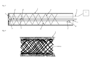
- FIG. 1 shows a first embodiment of the endoscope according to the invention, which shows within a shell 1 axially spaced rings 2, which extend at a radial distance about the longitudinal central axis of the endoscope and which are arranged over at least part of the length of the endoscope. In the sectional plane, the rings 2 are cut and shown below in plan view.
- a sensor surface 5 of a detection device arranged, in particular an optical detector or the end face of an optical glass fiber.
- the sensor surface 5 is connected by means of a data line 6, which is for example an electrical cable or a glass fiber, and is arranged along the endoscope, with a screen 7 as a display unit.
- At least one shape memory alloy element 8 is arranged, which is fastened to the distal end 3 of the endoscope and in the region of the proximal end 4.
- the Endopskop is flexible in the extended state of the element 8 with shape memory alloy, since the rings 2 are spaced apart and movable relative to each other, while contracted state of the shape memory alloy element, the rings 2 are arranged non-positively and / or positively against each other, and the endoscope has a higher stiffness.
- the endoscope of this embodiment has higher flexibility or lower rigidity than in the contracted state of the shape memory alloy element.
- the latter For bending at least the portion of the endoscope adjacent to the distal end 3, the latter has at least one control wire 9 extending along the endoscope, which can be tensioned by means of an actuator 10, which is preferably arranged at the proximal end 4 of the endoscope. Because of the eccentric arrangement of the control wire 9, the application of a voltage to the control wire 9 by means of the actuator 10 leads to a bending of the endoscope.
- the working channel 11 runs along the endoscope and, as shown, can be arranged within the casing 1 or inside the endoscope, preferably coaxially in the endoscope, or rest on the outside of the casing 1.
- the container 12 is arranged, the proximal end 13 of which is connected to the distal end 15 of the flexible conduit 16, preferably by means of a connecting sleeve 14, the container 12 at its proximal end 13 and the flexible conduit 16 at its distal end 15 surrounds.
- the container 12 has at its proximal end 13 an inlet port connected to the volume of the flexible conduit 16, and at its opposite distal end 17 a Outlet opening through which emerges when pressurizing the flexible conduit 16 from the proximal end 4 of the endoscope containing the sperm contained in the container 12 liquid.
- FIG. 2 shows an alternative embodiment of the endoscope, in which the radially spaced from the longitudinal axis of the endoscope elements, each axially spaced, are integrally formed in the form of a first spiral 18.
- the contraction of an element 8 with shape memory alloy leads to the frictional and / or form-fitting arrangement of the respective end faces of the spiral 18 against each other, and thus to a higher rigidity of the endoscope.
- the higher rigidity of the endoscope is set at least in the portion extending from the proximal end of the endoscope to the portion located within the cervix to allow it to pass and advance the endoscope, while the shape memory alloy element in the endoscope Section, which is located uterus side of the cervix, or within the uterus, within a uterine horn to the utero-tubal connection is present in the first embodiment in the expanded or non-contracted state, so that there the endoscope is flexible to use the Actuation of a control wire 9 by means of an actuator 10, the curvature of the endoscope is controllable.
- the optical control of the positioning of the endoscope is effected by means of the image displayed on the screen 7 as a display unit, which is received by the sensor surface 5.
- the uterus is insufflated during the procedure, and accordingly the endoscope according to the invention preferably has an insufflation line 19 arranged along the endoscope, which serves to transport a medium for insufflation, and in particular opens at the distal end 3 of the endoscope.
- the conduit 19 may be placed outside the jacket 1 for insufflation, or inside the jacket 1.
- FIG. 3 FIG. 12 shows the embodiment in which the endoscope is stiffenable by integrally forming the axially spaced apart axially spaced elements integrally in the form of a first spiral 18 and the shape memory alloy element 8 forming a coaxial spiral therein, integrally or externally formed radially spaced from the longitudinal central axis of the endoscope elements 18.
- the stiffening mechanism of the endoscope may consist of only the shape memory alloy helical element 8 and the opposing first helix 18 which integrally form the axially spaced elements.
- stiffening of the endoscope is achieved by frictionally placing the shape memory alloy helical member 8 against the first helix 18 in a state while spacing the helical shaped memory alloy member 8 from the first helix 18, the endoscope has greater flexibility ,
- the endoscope can be stiffened by means of an element 8 made of shape memory metal that adjacent to or within the shell 1, a braid of wires or elements 8 of a shape memory alloy is arranged.
- the forming elements of the endoscope or the longitudinal stiffness of the endoscope determining elements of this embodiment of the mantle comprised braid of elements 8 made of shape memory alloy, at least one control wire 9, which is disposed within the braid of elements 8 with shape memory alloy, wherein the Control wire 9 is connected at its one end to the endoscope and is connected at its other end to an actuator 10, which can exert a controlled force on the control wire 9.
- the working channel 11 is arranged, in which the flexible conduit 16 is longitudinally displaceable, at the distal end 15 of which the container 12 containing sperm-containing fluid is located, at the distal end 3 of the endoscope a sensor surface 5 is arranged, which is connected by means of a longitudinally extending through the endoscope data line 6 with a screen 7;
- the endoscope of this embodiment also preferably has a line 19 extending along the endoscope for an insufflation medium whose outlet opening is arranged in a section adjoining the distal end 3 of the endoscope, preferably at the distal end 3 of the endoscope.
- the insufflation medium conduit 19 may be formed by the clear cross section between the working channel 11 and the flexible conduit 16 disposed therein.
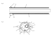
- FIG. 5 shows a rigid guide member 30 in longitudinal section with coaxially therein longitudinally guided endoscope.
- the guide member according to the preferred embodiment, at the end, the uterus paragraph arranged against the cervix is, an expandable as an inflatable balloon 31 or spreadable clip 32 trained expandable element 31, 32.
- the stiffness required for the passage of the cervix Z is created for the endoscope by placing the rigid guide member 30 around the endoscope so that the endoscope can be permanently flexible and the portionwise stiffness is created by the rigid guide member 30 ,
- the clasp 32 can be actuated, for example, by a puller wire 33 which runs along the guide element 30.
- the balloon 31 may be actuated, for example, by a hose 34 running along the guide element 30.
- FIG. 6 shown cross-section through the distal end of the endoscope with optionally the endoscope at least partially comprehensive rigid guide member 30 shows the sensor surface 5 and formed by the distal end 17 of the container 12 for the sperm-containing liquid within the spaced from the longitudinal axis of the endoscope elements, as Rings 2 or in one piece may be formed as a first spiral 18, for example with guided in eyelets 21 elements 8 with shape memory alloy.
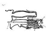
- FIG. 7 schematically shows the arrangement of the rigid guide member 30 through the cervix Z of a bovine until the distally mounted at the distal end of the rigid guide member 30 Absp Dahlbare element 31, 32 U against the cervix Z abuts.
- the expandable element 31, 32 preferably serves to seal the uterus U during its insufflation.
- the spanned by the rigid guide member 30 cross-section through the cervix Z is used for longitudinally displaceable recording of the endoscope.
- FIGS. 8 and 9 show optional interlocking projections and recesses 20, each of which can be arranged opposite one another on end faces of the rings 2, by means of which spaced from the longitudinal central axis of the endoscope, axially spaced elements form-fit interlock with contraction of a shape memory alloy element 8 and stiffen the endoscope.
- FIG. 10 schematically shows a positioning aid with a receiving recess 40 which is formed in a base plate 41.
- On both sides of the receiving recess 40 at least partially formed guide funnel or guide surfaces 42, 43 are formed.
- the connecting sleeve 14 is arranged in the receiving recess 40, wherein the container 12 and the flexible conduit 16 respectively along the surface a proportionate guide funnel 42, 43 are guided in the direction of the receiving recess 40, and thus in the connecting sleeve 14.
- pressure body 44 pressure on the connecting sleeve 14 can be exerted while it is arranged in the receiving recess 40 .
- the pressure body 44 are preferably mounted on a pivotally mounted on the base plate 41 carrier 45.
- Example 1 Deep freezing of bull sperm in containers made of PTFE with 0.4 to 0.56 mm inner diameter, 0.23 mm wall thickness
- Freshly collected bull sperm were diluted to 500,000 sperm per 20 ⁇ L in standard Tris egg yolk diluent, cooled to 5 ° C and then added with antifreeze (glycerol) to 2 to 15% and into PTFE tubing having an inner diameter of about 0.5 mm retracted, total volume about 20 ⁇ L.
- the container was ultrasonically sealed on both sides and placed in a conventional container for artificial insemination (Straw) with 2 mm inner diameter, which was also sealed on both sides by welding.
- the containers were stored for 45 minutes in a tempered at 12 ° C refrigerator, then for 2 h in a refrigerator of 5 ° C.
- the freezing was carried out by cooling at a rate of -2 ° C / min to -8 ° C and then at a rate of -10 ° C / min in nitrogen vapor to -130 ° C, followed by transfer to liquid nitrogen.
- the containers were removed from the liquid nitrogen and allowed to thaw by incubating in air at room temperature for 1 to 5 minutes.
- the diluted sperm were measured before freezing and after freezing after staining with the fluorescent dye SYBR14 in combination with PI (propidium iodide) by FACS to check their membrane integrity (PI-negative have undamaged membranes), and the Mobility was determined in the automated procedure according to CASA.
- a sperm-containing liquid can be cooled and deep-frozen in a container with a very small inner diameter, in particular with a diameter of less than 0.6 mm, and then thawed so that fertile spermatozoa are contained in the container.
- insemination rates for artificial insemination depend on farm, cattle herd and bulls
- three control groups of conventional artificial insemination were included in the uterine body in parallel, each with 15 million sperm in the experimental month (parallel), in the previous month (before) and in the month Month after the experiment (after), a total of 578 animals. These sperm came from all bulls used on the farm. With the method according to the invention, a total of 60 animals were occupied, each with 850,000 to 1.1 million sperm, which were placed in the utero-tubal connection.
- the positive pregnancy examination shows that with the method according to the invention for the bull a mean pregnancy rate of 30% was achieved, while in all three control groups a pregnancy rate of 31.8% was achieved. This demonstrates that pregnancy using a significantly lower number of spermatozoa was possible with the method of the invention, at approximately comparable pregnancy rates.
- Example 3 Transfer of sperm into the fallopian tube with low sperm count
Landscapes
- Life Sciences & Earth Sciences (AREA)
- Health & Medical Sciences (AREA)
- Veterinary Medicine (AREA)
- Animal Husbandry (AREA)
- Reproductive Health (AREA)
- Engineering & Computer Science (AREA)
- Wood Science & Technology (AREA)
- Zoology (AREA)
- Animal Behavior & Ethology (AREA)
- General Health & Medical Sciences (AREA)
- Public Health (AREA)
- Endoscopes (AREA)
Applications Claiming Priority (1)
| Application Number | Priority Date | Filing Date | Title |
|---|---|---|---|
| DE201110076844 DE102011076844A1 (de) | 2011-05-31 | 2011-05-31 | Endoskop zum Gametentransfer |
Publications (3)
| Publication Number | Publication Date |
|---|---|
| EP2529695A2 true EP2529695A2 (fr) | 2012-12-05 |
| EP2529695A3 EP2529695A3 (fr) | 2013-03-06 |
| EP2529695B1 EP2529695B1 (fr) | 2016-10-26 |
Family
ID=46245852
Family Applications (1)
| Application Number | Title | Priority Date | Filing Date |
|---|---|---|---|
| EP12170102.3A Not-in-force EP2529695B1 (fr) | 2011-05-31 | 2012-05-30 | Endoscope pour transfert de gamètes |
Country Status (2)
| Country | Link |
|---|---|
| EP (1) | EP2529695B1 (fr) |
| DE (1) | DE102011076844A1 (fr) |
Cited By (1)
| Publication number | Priority date | Publication date | Assignee | Title |
|---|---|---|---|---|
| FR3027509A1 (fr) * | 2014-10-28 | 2016-04-29 | Herritech | Appareil d'aide a la penetration vaginale d'animaux comportant un systeme de vision, notamment pour localiser le col de l'uterus |
Citations (5)
| Publication number | Priority date | Publication date | Assignee | Title |
|---|---|---|---|---|
| EP0214043A1 (fr) | 1985-08-19 | 1987-03-11 | Etablissement public dit: INSTITUT NATIONAL DE LA RECHERCHE AGRONOMIQUE | Instrument et procédé pour l'insémination artificielle, la transplantation d'embryons in-utéro ou le prélèvement de liquide folliculaire par voie transpéritonéale chez les animaux |
| DE29703451U1 (de) | 1997-02-26 | 1998-06-25 | Minitüb Abfüll- und Labortechnik GmbH & Co KG, 84184 Tiefenbach | Besamungskatheter, insbesondere für Schweine |
| EP1177776B1 (fr) | 2000-01-20 | 2004-05-06 | Universidad de Murcia | Dispositif et methode permettant d'introduire et/ou de prelever des fluides a l'interieur de l'uterus d'un animal |
| WO2006029653A1 (fr) | 2004-09-16 | 2006-03-23 | Masterrind Gmbh | Procede de preservation et de selection specifique au sexe de spermatozoides de mammiferes |
| DE19606925B4 (de) | 1995-02-13 | 2006-03-23 | Schnorrenberg, Arno | Besteck zur künstlichen Besamung von Elefanten und dessen Verwendung |
Family Cites Families (6)
| Publication number | Priority date | Publication date | Assignee | Title |
|---|---|---|---|---|
| FR2713492B1 (fr) * | 1993-12-09 | 1996-02-16 | Microfil Ind Sa | Guide tubulaire orientable, notamment pour un dispositif médico-chirurgical. |
| US6749560B1 (en) * | 1999-10-26 | 2004-06-15 | Circon Corporation | Endoscope shaft with slotted tube |
| AU2001276941A1 (en) * | 2000-07-14 | 2002-01-30 | Dennis D. Gourley | Apparatus and method for artificial insemination and embryo transfer of animals |
| US20040031071A1 (en) * | 2000-10-05 | 2004-02-12 | Xy, Inc. | System of hysteroscopic insemination of mares |
| US6527703B2 (en) * | 2001-06-14 | 2003-03-04 | Minitube Of America, Inc. | Device for sow-intra-uterine insemination and embryo transfer |
| JP2011045521A (ja) * | 2009-08-27 | 2011-03-10 | Hoya Corp | 内視鏡の可撓管とその製造方法 |
-
2011
- 2011-05-31 DE DE201110076844 patent/DE102011076844A1/de not_active Withdrawn
-
2012
- 2012-05-30 EP EP12170102.3A patent/EP2529695B1/fr not_active Not-in-force
Patent Citations (5)
| Publication number | Priority date | Publication date | Assignee | Title |
|---|---|---|---|---|
| EP0214043A1 (fr) | 1985-08-19 | 1987-03-11 | Etablissement public dit: INSTITUT NATIONAL DE LA RECHERCHE AGRONOMIQUE | Instrument et procédé pour l'insémination artificielle, la transplantation d'embryons in-utéro ou le prélèvement de liquide folliculaire par voie transpéritonéale chez les animaux |
| DE19606925B4 (de) | 1995-02-13 | 2006-03-23 | Schnorrenberg, Arno | Besteck zur künstlichen Besamung von Elefanten und dessen Verwendung |
| DE29703451U1 (de) | 1997-02-26 | 1998-06-25 | Minitüb Abfüll- und Labortechnik GmbH & Co KG, 84184 Tiefenbach | Besamungskatheter, insbesondere für Schweine |
| EP1177776B1 (fr) | 2000-01-20 | 2004-05-06 | Universidad de Murcia | Dispositif et methode permettant d'introduire et/ou de prelever des fluides a l'interieur de l'uterus d'un animal |
| WO2006029653A1 (fr) | 2004-09-16 | 2006-03-23 | Masterrind Gmbh | Procede de preservation et de selection specifique au sexe de spermatozoides de mammiferes |
Cited By (5)
| Publication number | Priority date | Publication date | Assignee | Title |
|---|---|---|---|---|
| FR3027509A1 (fr) * | 2014-10-28 | 2016-04-29 | Herritech | Appareil d'aide a la penetration vaginale d'animaux comportant un systeme de vision, notamment pour localiser le col de l'uterus |
| WO2016066962A1 (fr) * | 2014-10-28 | 2016-05-06 | Herritech | Appareil pour la pénétration vaginale d'animaux comportant un système de vision, notamment pour localiser le col de l'utérus |
| CN107072763A (zh) * | 2014-10-28 | 2017-08-18 | Imv技术股份有限公司 | 包括特别用于定位宫颈的观察系统的用于动物阴道深入的器具 |
| US10687928B2 (en) | 2014-10-28 | 2020-06-23 | Imv Technologies | Apparatus for vaginal penetration of animals comprising a viewing system, in particular for locating the cervix of the uterus |
| CN107072763B (zh) * | 2014-10-28 | 2021-11-09 | Imv技术股份有限公司 | 包括特别用于定位宫颈的观察系统的用于动物阴道深入的器具 |
Also Published As
| Publication number | Publication date |
|---|---|
| DE102011076844A1 (de) | 2012-12-06 |
| EP2529695A3 (fr) | 2013-03-06 |
| EP2529695B1 (fr) | 2016-10-26 |
Similar Documents
| Publication | Publication Date | Title |
|---|---|---|
| DE60010455T2 (de) | Vorrichtung und verfahren zum einbringen oder entnehmen von flüssigkeiten aus dem inneren des uterus eines tieres | |
| DE69128824T2 (de) | Injektionskatheter | |
| DE60109935T2 (de) | Kälteerzeugender ballonkatheter | |
| EP2326272B1 (fr) | Instrument cryochirurgical pour l'obtention d'un échantillon de tissu | |
| DE69423295T2 (de) | Katheter zur Kryo-Abtragung | |
| DE4419726C2 (de) | Vorrichtung zur künstlichen Befruchtung und Embryonenüberführung | |
| DE69618810T2 (de) | Fassvorrichtung zum einführen in ein körpergefäss | |
| DE2559571C3 (de) | Vorrichtung zum Lokalisieren und Entfernen eines Fremdkörpers aus einem Hohlorgan oder Kanal des Korpers eines Lebewesens | |
| AT504989B1 (de) | Punktionsvorrichtung für die entnahme einer organischen probe, sowie führungsadapter zur befestigung einer punktionsvorrichtung an einem ultraschallkopf | |
| DE2540120A1 (de) | Vorrichtung zum herausspuelen von eizellen aus kuehen oder stuten | |
| DE2804058A1 (de) | Medizinisches geraet zur entfernung von fremdkoerpern aus einem koerperhohlraum | |
| DE2359085A1 (de) | Perinealer retraktor | |
| DE2033665A1 (de) | Medizinisches Instrument lnsbe sondere zur Fetal Blutentnahme | |
| DE2426781C3 (de) | Vorrichtung zum Durchtrennen des verengten Schließmuskels der Mündung des Gallenganges in den Zwölffingerdarm | |
| DE60119744T2 (de) | Vorrichtung zur abnahme von tierischer samenflüssigkeit | |
| DE69811653T2 (de) | Vorrichtung zür künstlichen befruchtung von zuchttieren sowie, insbesondere, säuen | |
| EP2401020B1 (fr) | Cathéter | |
| DE102012104381A1 (de) | Medizinisches System zum endovaskulären Temperieren von Blut und medizinischer Katheter | |
| DE29813921U1 (de) | Vorrichtung zur Besamung von Tieren, insbesondere Sauen | |
| EP2529695B1 (fr) | Endoscope pour transfert de gamètes | |
| DE102013212448A1 (de) | Führungskatheter mit Verankerungsmechanismus und Verfahren zum Einführen eines Führungskatheters | |
| EP2329793B1 (fr) | Cathéter pour insémination artificielle | |
| EP1721579B1 (fr) | Cathéter pour transfert d'embryon | |
| DE102014008187B4 (de) | Hochdruck-Reinigungsinstrument und Reinigungsverfahren | |
| DE69906320T2 (de) | Kryochirurgisches instrument |
Legal Events
| Date | Code | Title | Description |
|---|---|---|---|
| PUAI | Public reference made under article 153(3) epc to a published international application that has entered the european phase |
Free format text: ORIGINAL CODE: 0009012 |
|
| AK | Designated contracting states |
Kind code of ref document: A2 Designated state(s): AL AT BE BG CH CY CZ DE DK EE ES FI FR GB GR HR HU IE IS IT LI LT LU LV MC MK MT NL NO PL PT RO RS SE SI SK SM TR |
|
| AX | Request for extension of the european patent |
Extension state: BA ME |
|
| PUAL | Search report despatched |
Free format text: ORIGINAL CODE: 0009013 |
|
| AK | Designated contracting states |
Kind code of ref document: A3 Designated state(s): AL AT BE BG CH CY CZ DE DK EE ES FI FR GB GR HR HU IE IS IT LI LT LU LV MC MK MT NL NO PL PT RO RS SE SI SK SM TR |
|
| AX | Request for extension of the european patent |
Extension state: BA ME |
|
| RIC1 | Information provided on ipc code assigned before grant |
Ipc: A61D 19/02 20060101AFI20130128BHEP |
|
| 17P | Request for examination filed |
Effective date: 20130906 |
|
| RBV | Designated contracting states (corrected) |
Designated state(s): AL AT BE BG CH CY CZ DE DK EE ES FI FR GB GR HR HU IE IS IT LI LT LU LV MC MK MT NL NO PL PT RO RS SE SI SK SM TR |
|
| 17Q | First examination report despatched |
Effective date: 20150213 |
|
| GRAP | Despatch of communication of intention to grant a patent |
Free format text: ORIGINAL CODE: EPIDOSNIGR1 |
|
| INTG | Intention to grant announced |
Effective date: 20160506 |
|
| GRAS | Grant fee paid |
Free format text: ORIGINAL CODE: EPIDOSNIGR3 |
|
| GRAA | (expected) grant |
Free format text: ORIGINAL CODE: 0009210 |
|
| AK | Designated contracting states |
Kind code of ref document: B1 Designated state(s): AL AT BE BG CH CY CZ DE DK EE ES FI FR GB GR HR HU IE IS IT LI LT LU LV MC MK MT NL NO PL PT RO RS SE SI SK SM TR |
|
| REG | Reference to a national code |
Ref country code: GB Ref legal event code: FG4D Free format text: NOT ENGLISH |
|
| REG | Reference to a national code |
Ref country code: CH Ref legal event code: EP |
|
| REG | Reference to a national code |
Ref country code: AT Ref legal event code: REF Ref document number: 839444 Country of ref document: AT Kind code of ref document: T Effective date: 20161115 |
|
| REG | Reference to a national code |
Ref country code: IE Ref legal event code: FG4D Free format text: LANGUAGE OF EP DOCUMENT: GERMAN |
|
| REG | Reference to a national code |
Ref country code: DE Ref legal event code: R096 Ref document number: 502012008615 Country of ref document: DE |
|
| REG | Reference to a national code |
Ref country code: LT Ref legal event code: MG4D |
|
| PG25 | Lapsed in a contracting state [announced via postgrant information from national office to epo] |
Ref country code: LV Free format text: LAPSE BECAUSE OF FAILURE TO SUBMIT A TRANSLATION OF THE DESCRIPTION OR TO PAY THE FEE WITHIN THE PRESCRIBED TIME-LIMIT Effective date: 20161026 |
|
| REG | Reference to a national code |
Ref country code: NL Ref legal event code: MP Effective date: 20161026 |
|
| PG25 | Lapsed in a contracting state [announced via postgrant information from national office to epo] |
Ref country code: LT Free format text: LAPSE BECAUSE OF FAILURE TO SUBMIT A TRANSLATION OF THE DESCRIPTION OR TO PAY THE FEE WITHIN THE PRESCRIBED TIME-LIMIT Effective date: 20161026 Ref country code: GR Free format text: LAPSE BECAUSE OF FAILURE TO SUBMIT A TRANSLATION OF THE DESCRIPTION OR TO PAY THE FEE WITHIN THE PRESCRIBED TIME-LIMIT Effective date: 20170127 Ref country code: SE Free format text: LAPSE BECAUSE OF FAILURE TO SUBMIT A TRANSLATION OF THE DESCRIPTION OR TO PAY THE FEE WITHIN THE PRESCRIBED TIME-LIMIT Effective date: 20161026 Ref country code: NO Free format text: LAPSE BECAUSE OF FAILURE TO SUBMIT A TRANSLATION OF THE DESCRIPTION OR TO PAY THE FEE WITHIN THE PRESCRIBED TIME-LIMIT Effective date: 20170126 |
|
| PG25 | Lapsed in a contracting state [announced via postgrant information from national office to epo] |
Ref country code: PL Free format text: LAPSE BECAUSE OF FAILURE TO SUBMIT A TRANSLATION OF THE DESCRIPTION OR TO PAY THE FEE WITHIN THE PRESCRIBED TIME-LIMIT Effective date: 20161026 Ref country code: RS Free format text: LAPSE BECAUSE OF FAILURE TO SUBMIT A TRANSLATION OF THE DESCRIPTION OR TO PAY THE FEE WITHIN THE PRESCRIBED TIME-LIMIT Effective date: 20161026 Ref country code: PT Free format text: LAPSE BECAUSE OF FAILURE TO SUBMIT A TRANSLATION OF THE DESCRIPTION OR TO PAY THE FEE WITHIN THE PRESCRIBED TIME-LIMIT Effective date: 20170227 Ref country code: IS Free format text: LAPSE BECAUSE OF FAILURE TO SUBMIT A TRANSLATION OF THE DESCRIPTION OR TO PAY THE FEE WITHIN THE PRESCRIBED TIME-LIMIT Effective date: 20170226 Ref country code: HR Free format text: LAPSE BECAUSE OF FAILURE TO SUBMIT A TRANSLATION OF THE DESCRIPTION OR TO PAY THE FEE WITHIN THE PRESCRIBED TIME-LIMIT Effective date: 20161026 Ref country code: ES Free format text: LAPSE BECAUSE OF FAILURE TO SUBMIT A TRANSLATION OF THE DESCRIPTION OR TO PAY THE FEE WITHIN THE PRESCRIBED TIME-LIMIT Effective date: 20161026 Ref country code: FI Free format text: LAPSE BECAUSE OF FAILURE TO SUBMIT A TRANSLATION OF THE DESCRIPTION OR TO PAY THE FEE WITHIN THE PRESCRIBED TIME-LIMIT Effective date: 20161026 Ref country code: NL Free format text: LAPSE BECAUSE OF FAILURE TO SUBMIT A TRANSLATION OF THE DESCRIPTION OR TO PAY THE FEE WITHIN THE PRESCRIBED TIME-LIMIT Effective date: 20161026 |
|
| REG | Reference to a national code |
Ref country code: DE Ref legal event code: R097 Ref document number: 502012008615 Country of ref document: DE |
|
| PG25 | Lapsed in a contracting state [announced via postgrant information from national office to epo] |
Ref country code: SK Free format text: LAPSE BECAUSE OF FAILURE TO SUBMIT A TRANSLATION OF THE DESCRIPTION OR TO PAY THE FEE WITHIN THE PRESCRIBED TIME-LIMIT Effective date: 20161026 Ref country code: RO Free format text: LAPSE BECAUSE OF FAILURE TO SUBMIT A TRANSLATION OF THE DESCRIPTION OR TO PAY THE FEE WITHIN THE PRESCRIBED TIME-LIMIT Effective date: 20161026 Ref country code: DK Free format text: LAPSE BECAUSE OF FAILURE TO SUBMIT A TRANSLATION OF THE DESCRIPTION OR TO PAY THE FEE WITHIN THE PRESCRIBED TIME-LIMIT Effective date: 20161026 Ref country code: EE Free format text: LAPSE BECAUSE OF FAILURE TO SUBMIT A TRANSLATION OF THE DESCRIPTION OR TO PAY THE FEE WITHIN THE PRESCRIBED TIME-LIMIT Effective date: 20161026 Ref country code: CZ Free format text: LAPSE BECAUSE OF FAILURE TO SUBMIT A TRANSLATION OF THE DESCRIPTION OR TO PAY THE FEE WITHIN THE PRESCRIBED TIME-LIMIT Effective date: 20161026 |
|
| PG25 | Lapsed in a contracting state [announced via postgrant information from national office to epo] |
Ref country code: IT Free format text: LAPSE BECAUSE OF FAILURE TO SUBMIT A TRANSLATION OF THE DESCRIPTION OR TO PAY THE FEE WITHIN THE PRESCRIBED TIME-LIMIT Effective date: 20161026 Ref country code: SM Free format text: LAPSE BECAUSE OF FAILURE TO SUBMIT A TRANSLATION OF THE DESCRIPTION OR TO PAY THE FEE WITHIN THE PRESCRIBED TIME-LIMIT Effective date: 20161026 Ref country code: LU Free format text: LAPSE BECAUSE OF NON-PAYMENT OF DUE FEES Effective date: 20170531 Ref country code: BG Free format text: LAPSE BECAUSE OF FAILURE TO SUBMIT A TRANSLATION OF THE DESCRIPTION OR TO PAY THE FEE WITHIN THE PRESCRIBED TIME-LIMIT Effective date: 20170126 |
|
| PLBE | No opposition filed within time limit |
Free format text: ORIGINAL CODE: 0009261 |
|
| STAA | Information on the status of an ep patent application or granted ep patent |
Free format text: STATUS: NO OPPOSITION FILED WITHIN TIME LIMIT |
|
| 26N | No opposition filed |
Effective date: 20170727 |
|
| PG25 | Lapsed in a contracting state [announced via postgrant information from national office to epo] |
Ref country code: SI Free format text: LAPSE BECAUSE OF FAILURE TO SUBMIT A TRANSLATION OF THE DESCRIPTION OR TO PAY THE FEE WITHIN THE PRESCRIBED TIME-LIMIT Effective date: 20161026 |
|
| REG | Reference to a national code |
Ref country code: CH Ref legal event code: PL |
|
| GBPC | Gb: european patent ceased through non-payment of renewal fee |
Effective date: 20170530 |
|
| PG25 | Lapsed in a contracting state [announced via postgrant information from national office to epo] |
Ref country code: MC Free format text: LAPSE BECAUSE OF FAILURE TO SUBMIT A TRANSLATION OF THE DESCRIPTION OR TO PAY THE FEE WITHIN THE PRESCRIBED TIME-LIMIT Effective date: 20161026 |
|
| REG | Reference to a national code |
Ref country code: IE Ref legal event code: MM4A |
|
| PG25 | Lapsed in a contracting state [announced via postgrant information from national office to epo] |
Ref country code: LI Free format text: LAPSE BECAUSE OF NON-PAYMENT OF DUE FEES Effective date: 20170531 Ref country code: CH Free format text: LAPSE BECAUSE OF NON-PAYMENT OF DUE FEES Effective date: 20170531 |
|
| REG | Reference to a national code |
Ref country code: FR Ref legal event code: ST Effective date: 20180131 |
|
| PG25 | Lapsed in a contracting state [announced via postgrant information from national office to epo] |
Ref country code: LU Free format text: LAPSE BECAUSE OF NON-PAYMENT OF DUE FEES Effective date: 20170530 |
|
| REG | Reference to a national code |
Ref country code: BE Ref legal event code: MM Effective date: 20170531 |
|
| PG25 | Lapsed in a contracting state [announced via postgrant information from national office to epo] |
Ref country code: GB Free format text: LAPSE BECAUSE OF NON-PAYMENT OF DUE FEES Effective date: 20170530 Ref country code: IE Free format text: LAPSE BECAUSE OF NON-PAYMENT OF DUE FEES Effective date: 20170530 |
|
| PG25 | Lapsed in a contracting state [announced via postgrant information from national office to epo] |
Ref country code: FR Free format text: LAPSE BECAUSE OF NON-PAYMENT OF DUE FEES Effective date: 20170531 |
|
| REG | Reference to a national code |
Ref country code: AT Ref legal event code: MM01 Ref document number: 839444 Country of ref document: AT Kind code of ref document: T Effective date: 20170530 |
|
| PG25 | Lapsed in a contracting state [announced via postgrant information from national office to epo] |
Ref country code: BE Free format text: LAPSE BECAUSE OF NON-PAYMENT OF DUE FEES Effective date: 20170531 Ref country code: AT Free format text: LAPSE BECAUSE OF NON-PAYMENT OF DUE FEES Effective date: 20170530 |
|
| PG25 | Lapsed in a contracting state [announced via postgrant information from national office to epo] |
Ref country code: MT Free format text: LAPSE BECAUSE OF FAILURE TO SUBMIT A TRANSLATION OF THE DESCRIPTION OR TO PAY THE FEE WITHIN THE PRESCRIBED TIME-LIMIT Effective date: 20161026 |
|
| PG25 | Lapsed in a contracting state [announced via postgrant information from national office to epo] |
Ref country code: HU Free format text: LAPSE BECAUSE OF FAILURE TO SUBMIT A TRANSLATION OF THE DESCRIPTION OR TO PAY THE FEE WITHIN THE PRESCRIBED TIME-LIMIT; INVALID AB INITIO Effective date: 20120530 |
|
| PG25 | Lapsed in a contracting state [announced via postgrant information from national office to epo] |
Ref country code: CY Free format text: LAPSE BECAUSE OF NON-PAYMENT OF DUE FEES Effective date: 20161026 |
|
| PG25 | Lapsed in a contracting state [announced via postgrant information from national office to epo] |
Ref country code: MK Free format text: LAPSE BECAUSE OF FAILURE TO SUBMIT A TRANSLATION OF THE DESCRIPTION OR TO PAY THE FEE WITHIN THE PRESCRIBED TIME-LIMIT Effective date: 20161026 |
|
| PG25 | Lapsed in a contracting state [announced via postgrant information from national office to epo] |
Ref country code: TR Free format text: LAPSE BECAUSE OF FAILURE TO SUBMIT A TRANSLATION OF THE DESCRIPTION OR TO PAY THE FEE WITHIN THE PRESCRIBED TIME-LIMIT Effective date: 20161026 |
|
| PG25 | Lapsed in a contracting state [announced via postgrant information from national office to epo] |
Ref country code: AL Free format text: LAPSE BECAUSE OF FAILURE TO SUBMIT A TRANSLATION OF THE DESCRIPTION OR TO PAY THE FEE WITHIN THE PRESCRIBED TIME-LIMIT Effective date: 20161026 |
|
| PGFP | Annual fee paid to national office [announced via postgrant information from national office to epo] |
Ref country code: DE Payment date: 20220523 Year of fee payment: 11 |
|
| REG | Reference to a national code |
Ref country code: DE Ref legal event code: R119 Ref document number: 502012008615 Country of ref document: DE |
|
| PG25 | Lapsed in a contracting state [announced via postgrant information from national office to epo] |
Ref country code: DE Free format text: LAPSE BECAUSE OF NON-PAYMENT OF DUE FEES Effective date: 20231201 |