EP2529843A2 - Rückflussdüse zur Erzeugung einer Kavitation oder Impulsstrahlen - Google Patents
Rückflussdüse zur Erzeugung einer Kavitation oder Impulsstrahlen Download PDFInfo
- Publication number
- EP2529843A2 EP2529843A2 EP11181273A EP11181273A EP2529843A2 EP 2529843 A2 EP2529843 A2 EP 2529843A2 EP 11181273 A EP11181273 A EP 11181273A EP 11181273 A EP11181273 A EP 11181273A EP 2529843 A2 EP2529843 A2 EP 2529843A2
- Authority
- EP
- European Patent Office
- Prior art keywords
- mixing chamber
- main
- nozzle
- channel
- flow
- Prior art date
- Legal status (The legal status is an assumption and is not a legal conclusion. Google has not performed a legal analysis and makes no representation as to the accuracy of the status listed.)
- Granted
Links
Images

Classifications
-
- B—PERFORMING OPERATIONS; TRANSPORTING
- B05—SPRAYING OR ATOMISING IN GENERAL; APPLYING FLUENT MATERIALS TO SURFACES, IN GENERAL
- B05B—SPRAYING APPARATUS; ATOMISING APPARATUS; NOZZLES
- B05B1/00—Nozzles, spray heads or other outlets, with or without auxiliary devices such as valves, heating means
- B05B1/02—Nozzles, spray heads or other outlets, with or without auxiliary devices such as valves, heating means designed to produce a jet, spray, or other discharge of particular shape or nature, e.g. in single drops, or having an outlet of particular shape
- B05B1/08—Nozzles, spray heads or other outlets, with or without auxiliary devices such as valves, heating means designed to produce a jet, spray, or other discharge of particular shape or nature, e.g. in single drops, or having an outlet of particular shape of pulsating nature, e.g. delivering liquid in successive separate quantities
Definitions
- the present invention relates generally to nozzles and, in particular, to nozzles for generating cavitating or pulsed jets.
- Cavitating jet generating devices have been known and documented in the technical literature. A number of patents have also issued pertaining to various cavitating jet systems.
- U.S. Patents 5,217,163 ; 5,154,347 ; 5,125,582 ; and 5,086,974 are examples of technologies already known in the art. Cavitation has been known as a deleterious factor, for example, in the marine industry where it may severely damage propellers and other underwater components of ships. When cavitation bubbles collapse on a surface, the collapsing bubbles produce very high-speed micro-jets which are responsible for the damage to the surface by erosion. The same erosive power of cavitation is beneficial when used in certain applications, for example fragmenting ore-bearing hard rocks in the mining industry or removing solid particles from a substrate, to name but a few possible applications.
- cavitating waterjet systems only produce effective high-speed cavitating jets when submerged.
- a high-speed continuous waterjet When a high-speed continuous waterjet is fully submerged in quiescent water, shear layers develop in the mixing zone of the jet and the still water. These shear layers produce vortices which give rise to cavitation bubbles (containing water vapor, not air) in the high-speed waterjet.
- Prior-art cavitating jets in air usually experience a loss of cavitating power due to a partial collapse of the vapor bubbles present in the cavitating jet after it leaves the nozzle. Because so much power is lost before it reaches the target object, the cavitating action on the surface of the target object is undesirably low.
- High-pressure non-cavitating jets can be used in the applications mentioned above (fragmenting, surface cleaning, etc.); it is known, however, that a cavitating jet can achieve the same erosive effect as a non-cavitating jet using considerably less pressure and hydraulic power. Therefore, employing cavitating jets can not only reduce the costs but also enhance operational safety.
- the reverse-flow nozzles disclosed in these publications utilized a continuous jet inlet and distinct lateral inlets for the reverse jet and the shroud jet.
- the nozzle design was thus complex as it required separate lateral inlets for the reverse jet and shroud jet.
- a simpler, more efficient, more practical and more cost-effective reverse-flow nozzle thus remained highly desirable.
- a solution to this technical problem is disclosed herein.
- the embodiments of the present invention provide an innovative nozzle and method for generating cavitating or pulsed jets of liquid, for example water, wherein the jets can be produced in an open atmosphere, without the need for submersion.
- the embodiments of the present invention also provide an innovative nozzle and method for generating cavitating jets of liquid wherein the jets retain, when reaching the target, a significant fraction of the cavitating bubbles initially present when discharged from the nozzle.
- one aspect of the present invention is a nozzle for generating a cavitating jet of pressurized liquid by generating cavitating vapor bubbles in a pressurized stream of the liquid supplied to the nozzle from a source of the pressurized liquid.
- This nozzle for generating a cavitating jet of pressurized liquid includes a main channel extending through the body of the nozzle.
- the main channel has a main inlet for receiving the pressurized liquid and a main outlet for discharging the pressurized liquid from the nozzle.
- the main channel includes a mixing chamber disposed between the inlet and the outlet.
- the nozzle also includes a flow-reversing channel having a first liquid-diverting inlet for diverting a portion of the pressurized liquid from a main stream flowing through the main channel.
- the flow-reversing channel includes a reverse-flow outlet connected to the mixing chamber for discharging a reverse flow of pressurized liquid into the mixing chamber.
- the reverse flow creates shear forces between the main stream and the reverse flow which generate cavitating bubbles in the main stream of pressurized liquid in the mixing chamber. This generates the cavitating jet.
- the nozzle further includes a shroud-generating channel having a second liquid-diverting inlet for receiving pressurized liquid from the mixing chamber and a shroud-jet outlet disposed radially outwardly of the main outlet of the main channel.
- the shroud-jet outlet discharges an annular shroud jet that enshrouds the cavitating jet discharging from the main outlet.
- the nozzle has a body comprising a main channel extending through the body.
- the main channel has an inlet for receiving the pressurized liquid and an outlet for discharging the pressurized liquid from the nozzle.
- the main channel includes a mixing chamber disposed between the inlet and the outlet.
- the nozzle also includes a flow-reversing channel having a first liquid-diverting inlet for diverting a portion of the pressurized liquid from a main stream flowing through the main channel and a reverse-flow outlet connected to the mixing chamber for discharging an angled reverse flow of pressurized liquid into the mixing chamber at an angle relative to the main stream to thereby intermittently interrupt the main stream, thereby generating the naturally pulsed jet.
- the nozzle further includes a shroud-generating channel having a second liquid-diverting inlet for receiving pressurized liquid from the mixing chamber and a shroud-jet outlet disposed radially outwardly of the main outlet of the main channel, the shroud-jet outlet discharging an annular shroud jet that enshrouds the pulsed jet discharged from the main outlet.
- the nozzle includes a nozzle body having a main inlet for receiving a stream of the pressurized liquid, a main channel extending through the nozzle body from the main inlet to a main outlet, and a flow-reversing channel in fluid communication with the main channel at a point upstream of a mixing chamber.
- This channel diverts into the flow-reversing channel a diverted portion of the liquid from the main channel and returns the diverted liquid to the mixing chamber as a reverse-flow jet relative to a main stream of liquid flowing toward the outlet.
- the reverse-flow jet interacts with the main stream to generate the cavitating jet that discharges from the main outlet.
- the nozzle includes a nozzle body having a main inlet for receiving a stream of the pressurized liquid, a main channel extending through the nozzle body from the main inlet to a main outlet, and a flow-reversing channel in fluid communication with the main channel at a point upstream of a mixing chamber for diverting into the flow-reversing channel a diverted portion of the liquid from the main channel and for returning the diverted liquid to the mixing chamber as a reverse-flow jet that is both reversed and angled relative to a main stream of liquid flowing toward the outlet.
- the reverse-flow jet intermittently interrupts the main stream to generate the naturally pulsed jet that discharges from the main outlet.
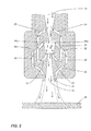
- Fig. 1 is a cross-sectional view of a nozzle in accordance with an embodiment of the present invention
- Fig. 2 is an enlarged cross-sectional view of the nozzle of Fig. 1 , schematically depicting flow patterns inside the nozzle;
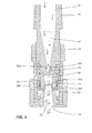
- Fig. 3 is a cross-sectional view of another nozzle in accordance with another embodiment of the present invention.
- Fig. 4 is a cross-sectional assembly view of the nozzle of Fig. 3 ;
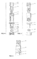
- Fig. 5 is an assembly view of the nozzle of Fig. 3 ;
- Fig. 6 is a view of the assembled nozzle of Fig. 3 .
- the nozzles disclosed herein create an internal reverse flow to generate a cavitating jet, a naturally pulsed jet or a combination of the two by virtue of the interaction between the main jet (main stream) and the reverse-flow jet (e.g. by virtue of shear forces at the interface).
- the nozzles may generate a cavitating or pulsed jet with or without a surrounding or annular shroud jet.
- the nozzle has a body (or nozzle body) comprising a main channel (which may be a central fluid flow channel) extending from a main inlet of the nozzle body to a main outlet of the nozzle body.
- the main inlet is disposed at an upstream end of the body for receiving a main stream (or main jet) of the pressurized liquid.
- pressurized liquid flows into the nozzle through the main inlet.
- the main outlet is disposed at a downstream end of the body for discharging the cavitating and/or pulsed jet of the pressurized fluid from the nozzle.
- the cavitating jet or pulsed jet discharges or exits from the nozzle through the main outlet.
- the main channel may be formed substantially centrally or axially through the body of the nozzle (i.e. the main channel may be a fluid passage that extends along a longitudinal central axis of the body).
- the main channel (central flow channel) includes or defines a mixing chamber disposed intermediate the main inlet and the main outlet. Interaction between the main jet and reverse-flow jet in the mixing chamber is what generates the cavitating and/or naturally pulsed jet.
- a first channel i.e. a flow-reversing channel
- This flow-reversing channel has an inlet (i.e. a liquid-diverting inlet) for diverting a portion of the pressurized liquid from the main stream or main jet.
- the diverted liquid flows through a loopshaped channel that reverses its direction of flow.
- An outlet of this channel i.e. a reverse-flow outlet
- the diverted liquid is discharged back into the mixing chamber in a direction reverse to the main stream, i.e. generally oppositely (counter-currently) to a direction of flow of the main stream of liquid.
- the reverse-flow jet provided by the flow-reversing channel creates shear forces and resulting cavitation bubbles in the liquid in the mixing chamber.
- An optional second channel may be provided in the nozzle body.
- This second (shroud-generating) channel has a second (liquid-diverting) inlet for receiving pressurized liquid from the mixing chamber.
- the second channel also has a shroud-jet outlet disposed radially outwardly of the main outlet of the main channel.
- the shroud-jet outlet discharges an annular shroud jet that enshrouds the cavitating jet discharged from the main outlet.
- the outlet may be disposed proximate the main outlet of the main channel and may be in a converging relationship to a longitudinal axis of the main channel in the direction of flow of the liquid through the main channel.
- the outlet is disposed such as to direct a stream of liquid towards, and generally co-currently with the direction of, the main stream of liquid discharged from the central channel.
- the shroud jet is discharged in the same direction as the cavitating or pulsed jet exiting the main outlet such that the shroud jet envelops or enshrouds the cavitating or pulsed jet.
- the liquid-diverting inlet of the first (flow-reversing) channel may be connected to a portion of the main channel upstream of the mixing chamber.
- the liquid-diverting inlet of the flow-reversing channel is connected (in fluid communication with) a converging section between the main inlet and the mixing chamber.
- the second liquid-diverting inlet of the second (shroud-generating) channel may be connected to the mixing chamber in a manner to receive pressurized liquid from the mixing chamber and discharge this liquid from the nozzle as an annular shroud of liquid surrounding and protecting the cavitating jet.
- the outlet of the second channel is disposed peripherally or tangentially to the main outlet of the main channel such as to provide a circumfluent stream of liquid towards the cavitating or pulsed jet leaving the central channel in a manner to envelop or enshroud the central stream.
- the outlet portion of the second channel is annular and concentric with the axis of the main channel at the main outlet of the nozzle.
- the outlet of the first channel is disposed at an angle of about 3 degrees to about 10 degrees to the longitudinal axis of the main channel. This results in the annular stream from the first channel "gently" contacting the central stream of fluid in the mixing chamber without significantly impairing the kinetic energy of the central stream while creating shear forces and resulting cavitational vapor bubbles at the interface of the two streams.
- the annular end portion (outlet) of the second channel is disposed at a small (highly oblique) angle to the axis of the main channel.
- the angle should be such as to enable the annular stream of fluid from the second annular channel to merge with, and envelop or enshroud, the central stream of fluid to protect the cavitational bubbles therein so that the bubbles remain within the jet until impact with the target.
- the shroud jet thus protects or retains the bubbles within the jet without significantly disturbing the main jet or impairing its kinetic energy.
- the cross-sectional dimensions (e.g. diameter) of the mixing chamber are, in one embodiment, significantly greater than the diameter of the narrowest spot ("the throat") of the converging section of the central channel, for two reasons: first, to create, in operation, a partial vacuum in the mixing chamber (according to the Bernoulli Theorem), and secondly, to accommodate, in operation, an increased flow of fluid, caused by the additional stream from the first channel.
- the diameter of the mixing chamber at its upstream end is greater than at its downstream end.
- cavitation can occur in any liquid.
- the dimensional number used to determine whether cavitation occurs or not is the "cavitation number," which is a function of local velocity and the dynamic pressure of the flow of liquid. Cavitation number, in turn, can depend on Reynolds number, etc.
- the occurrence of cavitation depends on the intensity of turbulence between the main (central flow) and the reverse flow, because turbulence, by definition, consists of eddies, and the pressure at the center of eddies can be quite low. If this pressure is equivalent to the vapor pressure of the liquid at the local temperature, then the liquid can flash into vapor, forming cavitation bubbles.
- Fig. 1 depicts a cross-sectional view of a nozzle body, generally designated by reference numeral 10, with a main channel (defined by various sections 12, 14, 16, 20, 18, 22 to be described below) extending through the nozzle body.
- the main channel which may have various different circular and varying cross-sections throughout its length, has a main inlet 12 and a main outlet 18 for, respectively, receiving a stream of pressurized liquid from a source of pressurized liquid (e.g. pump, not shown) and discharging the stream of pressurized liquid towards a target 38 (or surface, object, work-piece, etc) shown in Fig. 2 .
- the direction of liquid flow through the main channel is indicated by arrows in Fig. 1 and Fig. 2 .
- the main channel may have a converging section 14 which converges (e.g. tapers linearly) in the direction of flow which extends into a cylindrical or tubular throat 16 (i.e. a tubular passageway of uniform circular cross-sectional area) which, in turn, extends into a mixing chamber 20, which may be a frustaconical mixing chamber 20.
- the angle of convergence, ⁇ can be from about 10 degrees to 45 degrees and preferably about 13 degrees to 25 degrees.
- Downstream of the mixing chamber 20 is an outlet section 22 of the central channel which terminates with the main outlet 18.
- the outlet section 22 leading to the main outlet 18 may have a diverging shape, as illustrated by way of example in Fig. 1 , with the angle of divergence being, for example, from about 10 degrees to about 25 degrees.
- the diameter of the mixing chamber 20 is greater than the diameter of the main channel on each of its ends adjacent the mixing chamber 20.
- the nozzle (or the nozzle body) includes a flow-reversing channel 24, 26, 28, 29 having first liquid-diverting inlets 24a, 26a for diverting a portion of the pressurized liquid from a main stream flowing through the main channel.
- the flow-reversing channels 24, 26, 28, 29 also include respective reverse-flow outlets 28a, 29a connected to the mixing chamber for discharging a reverse flow of pressurized liquid into the mixing chamber relative to the main stream to thereby generate the cavitating or naturally pulsed jet.
- the flow-reversing channels may include angled channel portions 24, 26 followed by parallel channel portions (parallel to a longitudinal axis of the main channel) and looped or curved channel portions 28, 29 that reverse the flow back into the mixing chamber.
- the nozzle includes two tubular channels 24, 26 that extend from the converging section 14, at a point near but upstream of the throat 16, into respective annular channels 28, 29 which reverse the flow and discharge the flow into the mixing chamber 20 at the downstream end of the mixing chamber 20.
- Curved or looped channel portions 28, 29 surround concentrically an upstream portion of the outlet section 22 of the main channel.
- the channel portions 28, 29 are disposed to direct a reverse-flow jet of liquid into the mixing chamber 20 at an angle ⁇ which may be from about 3 to 7 degrees. While Fig.
- each of the annular channel portions 28, 29 shows the cross-sectional dimension, or width D', of each of the annular channel portions 28, 29 to be similar to the diameter of the inlet channel portions 24, 26, it will be understood that the former, in order to retain the linear velocity of the stream of fluid carried therethrough, should be much smaller than the latter since the curved channel portions 28, 29 carry the same flow as the two inlet channel portions 24, 26.
- the channels 24, 26, 28, 29 together form the flow-reversing channel(s).
- the main channel provides a straight (linear) path of liquid flow through the converging section 14, the throat 16 and the mixing chamber 20, while channels 24, 26, 28 and 29 provide an alternative fluid flow route between the converging section 14 and the mixing chamber 20.
- two shroud-generating channels (collectively designated by reference numerals 30, 32, 34, 35, 36) have second liquid-diverting inlets 34a that draw liquid from an upstream end of the mixing chamber 20 into angled inlet channel portions 30, 32 which deliver the liquid to substantially parallel annular channel portions 34 which in turn deliver the liquid into curved, converging channel portions 35.
- These curved, converging channel portions 35 terminate in shroud-jet outlets 36 for discharging an annular shroud jet.
- the shroud-generating channels are radially spaced from the flow-reversing channels.
- the actual dimension D" of the channel portion 35 is smaller than the diameter of the channel portions 30, 34. This relationship prevents a significant reduction of the velocity of fluid flow in the annular channel 35 compared to the velocity of flow in the channels 30, 34.
- the diameters, or widths, of all the channels described and illustrated herein are selected so that, in operation, the velocity of flow of liquid discharged towards the target surface 38 from the outlet 18 of the central channel is substantially equal to the velocity of the stream discharged from the outlet 36. This enables the two streams to merge relatively smoothly, without the central stream of liquid losing much energy, while the annular stream of liquid from outlet(s) 36 envelops (or enshrouds) the central stream (main jet) and protects the cavitating bubbles therein.
- the annular channel portion 35 has an outlet 36 substantially adjacent or very near (i.e. in very close proximity to) the main outlet 18 of the central (main) channel. As shown by way of example, the channel portion 35 may taper in a curved and converging manner towards the main outlet 18. In the embodiment illustrated herein, the annular channel portion 35 at its outlet 36 surrounds concentrically the main outlet 18 of the central (main) channel and is spaced therefrom by a very small amount.
- the outlet 36 of the annular channel portion 35 merges partly or entirely with the main outlet 18 of the central (main) channel, provided that the angle ⁇ , defined by the directions of flow through the shroud-jet outlet 36 and the main outlet 18 is small, e.g. in the order of 5-10 degrees, such that the two streams, one from the central channel and the other annular stream from the channel 35, can merge smoothly without undue disturbance.
- Fig. 2 illustrates the fluid flow within the exemplary nozzle of Fig. 1 .
- a pressurized stream of liquid e.g. water
- a source e.g. a pump
- the main stream is diverted near the downstream end of the converging section 14 into a main axial, central stream (a main jet) and two (or more) shunted (bypass) streams which are forced by the pressure of water in the converging section 14 to pass through the flow-reversing channels.
- an annular stream of liquid e.g.
- This reverse-flow jet may be substantially parallel or slightly angled relative to the longitudinal axis of the main jet flowing through the central channel and mixing chamber.
- the two counter-current streams shear against each other as they merge thereby creating shear forces dependent on the pressure of liquid and the dimensions and configuration of the channel(s) and the mixing chamber.
- the shear forces at the interface of the main jet and the reverse-flow jet create cavitation in the liquid.
- the cavitating liquid contains vapor bubbles, the bubbles being immediately carried by the central stream of liquid towards the main outlet of the main channel.
- the excess pressure and volume of liquid in the mixing chamber caused by the annular stream from the reverse-flow channel result in some fluid from the mixing chamber being forced through the channels 30, 32 which are connected to the mixing chamber at its upstream end, and through the collecting channel 34 and the curved annular channel 35 to its outlet 36 located near the main outlet 18 of the central main channel.
- the converging shape of the channel portion 35 combined with a small angle ⁇ between the shroud jet and main jet causes the annular stream discharged from the shroud-jet outlet(s) 36 to create a sheath, envelope or shroud of fluid around the central stream of fluid discharged from the main outlet 18.
- the shroud jet protects the cavitation bubbles in the main cavitating jet in a manner similar to that of the surrounding liquid in a submerged jet.
- the protection is effective for a substantial stand-off distance, enabling the cavitating nozzle to be used in open air (i.e. without being submerged as required by the prior-art designs).
- a nozzle in accordance with another embodiment of the present invention is illustrated in Fig. 3 to Fig. 6 .
- the nozzle body 10 has a main channel (which may be a central or axial flow channel) which defines a main inlet 12, a converging section 14, a mixing chamber 20 and a main outlet 18.
- the nozzle may have a linearly diverging outlet section 22 leading from the mixing chamber 20 to the main outlet 18.
- the nozzle depicted in Fig. 3 to Fig. 6 includes only the flow-reversing channel(s) but not the shroud-generating channel(s) disclosed and depicted with reference to the nozzle of Fig. 1 and Fig. 2 .
- This nozzle may be used to generate a cavitating jet without a shroud jet.
- This nozzle (or "reverse-flow cavitation nozzle”) includes a nozzle body 10 having a main inlet 12 for receiving a stream of the pressurized liquid.
- a main channel extends through the nozzle body 10 from the main inlet 12 to a main outlet 18.
- a flow-reversing channel 24, 26 in fluid communication with the main channel at a point upstream of a mixing chamber 20 diverts into the flow-reversing channel 24, 26 a diverted portion of the liquid from the main channel.
- This diverted liquid is returned to the mixing chamber as a reverse-flow jet relative to a main stream of liquid flowing toward the main outlet 18.
- the reverse-flow jet interacts with the main stream to generate the cavitating jet that discharges from the main outlet 18.
- the reverse-flow cavitation nozzle comprises a converging section 14 between the main inlet 12 and the mixing chamber 20.
- the liquid-diverting inlet(s) 24a, 26a of the flow-reversing channel(s) 24, 26 may be in fluid communication with the converging section 14.
- the nozzle of Fig. 3 may include a throat 16 of uniform circular cross-sectional area downstream of the converging section 14, and a frustaconical mixing chamber 20 downstream of the throat 16.
- the liquid-diverting inlet(s) 24a, 26a of the flow-reversing channel 24, 26 are in fluid communication with the converging section 14 while the reverse-flow outlet(s) 28a, 29a of the flow-reversing channel(s) 24, 26 are in fluid communication with a downstream end of the mixing chamber 20.
- the channels 24, 26 discharge into an annular space 27 concentric to an upstream portion of the outlet section 22. Liquid flows back from this annular space 27 into the mixing chamber 20 or into an intermediate chamber 20a disposed between the mixing chamber 20 and the outlet section 22.
- the intermediate chamber may have an outwardly curved (diverging) shape as shown by way of example in Fig. 3 and Fig. 4 .
- the top (upstream) end of the male insert 25 protrudes into the intermediate chamber.
- the intermediate chamber and mixing chamber may be formed within the female insert 19 as shown by way of example in Fig. 4 .
- the mixing chamber 20 may have a frustaconical shape disposed axially along a direction of fluid flow. In one embodiment, a diameter of the mixing chamber 20 at the upstream end of the mixing chamber is greater than a diameter of the mixing chamber at the downstream end of the mixing chamber.
- a variant of the nozzle depicted in Fig. 3 may be used as a reverse-flow nozzle for generating a naturally pulsed jet of pressurized liquid.
- the variant (pulse-generating) nozzle uses a reverse-flow jet that is both reversed and angled relative to a main stream of liquid flowing toward the main outlet.
- the angled reverse-flow jet intermittently interrupts the main stream to generate the naturally pulsed jet.
- Fig. 4 to Fig. 6 show exemplary components that can be used to assemble the nozzle of Fig. 3 (in cross-section in Fig. 4 , as an exploded (assembly) view in Fig. 5 and as an assembled view in Fig. 6 ).
- the nozzle includes an upper nozzle body (or inlet fixture) 10 having external threads, an O-ring, gasket or other sealing element 13, a housing 15 having internal and external threads, a jam nut 17, a female insert 19, an O-ring, gasket or other sealing element 21, a male insert 23 and a positioning nut 25.
- the components presented in Fig. 4 to Fig. 6 represent the best mode of manufacturing the nozzle (i.e. the most cost-effective way of machining the various parts). However, it should be appreciated that the nozzle of Fig. 3 to Fig. 6 may be manufactured in other ways with parts that are machined, cast or otherwise made of other forms or using other fabrication techniques.
- the nozzle depicted by way of example in Fig. 3 to Fig. 6 may generate a cavitating jet or a naturally pulsed jet or a jet that is both cavitating and pulsed (or that fluctuates between these two modes).
- a pulsed jet may form instead of a cavitating jet depending on how the reverse flow occurs through the narrow passages in the nozzle. It is believed that if the reverse flow is truly parallel to the main flow, cavitation is the dominant mechanism. Cavitation is believed to occur at the interface of the two mixing layers, i.e. at the interface of the central stream and the reverse-flow annular stream.
- the reverse flow impinges (that is, flows) at a slight angle to the central jet, then the reverse flow may momentarily interrupt the main jet, causing the formation of an interrupted jet.
- the momentary interruptions in the main jet create a pulsed jet (referred to herein as a natural pulsed jet because it occurs basically due to the interaction between the two streams, without any external excitation, that is, not forced as is the case with forced pulsed waterjet (FPWJ) such as disclosed in U.S. Patent Serial Number 7,594,614 (Ultrasonic Waterjet Apparatus).
- FPWJ forced pulsed waterjet
- cavitation occurs or pulses occur (or an intermittent combination of both).
- an assumption can be made that cavitation dominates (using the nozzles disclosed herein) because of the signature bell-shaped erosion curve as a function of standoff distance.
- this bell-shaped erosion curve is usually associated with cavitation.
- the nozzles disclosed herein can thus be used (or adapted or modified for use) to generate not only a cavitating jet but also a (natural) pulsed jet.
- the jet may be purely cavitating while in other cases the jet may be purely pulsed.
- the jet may be a hybrid, i.e. simultaneously both cavitating and pulsed.
- Each of the nozzles described above and depicted in the accompanying figures is a single device that generates, using a single source of pressurized liquid, a cavitating or naturally pulsed stream that may be optionally surrounded by a protective envelope or shroud in the form of a shroud jet.
- This cavitating or pulsed jet can thus be projected through air (i.e. it need not be submerged).
- This cavitating or pulsed jet may be used to cut, fracture, or abrade materials.
- the nozzle may be used for cavitation shotless peening (CSP), i.e. waterjet peening that does not require shot.
- CSP cavitation shotless peening
- This technology may be used for a wide variety of applications, including surface preparation, coating removal, cutting materials, fracturing matter like rocks, etc.
- the nozzle may be designed for pulsed and/or cavitating jets, with or without a shroud jet.
- an aspect of the invention is a reverse-flow cavitation nozzle for generating a cavitating jet of pressurized liquid, the nozzle comprising a nozzle body having a main inlet for receiving a stream of the pressurized liquid; a main channel extending through the nozzle body from the main inlet to a main outlet; a flow-reversing channel in fluid communication with the main channel at a point upstream of a mixing chamber for diverting into the flow-reversing channel a diverted portion of the liquid from the main channel and for returning the diverted liquid to the mixing chamber as a reverse-flow jet relative to a main stream of liquid flowing toward the outlet, wherein the reverse-flow jet interacts with the main stream to generate the cavitating jet that discharges from the main outlet.
- the reverse-flow cavitation nozzle comprises a converging section between the main inlet and the mixing chamber.
- a liquid-diverting inlet of the flow-reversing channel is in fluid communication with the converging section.
- the reverse-flow cavitation nozzle comprises a converging section between the main inlet and the mixing chamber, a throat of uniform cross-sectional area downstream of the converging section, and a frustaconical mixing chamber downstream of the throat.
- a liquid-diverting inlet of the flow-reversing channel is in fluid communication with the converging section and a reverse-flow outlet of the flow-reversing channel with a downstream end of the mixing chamber.
- the mixing chamber has a frustaconical shape disposed axially along a direction of fluid flow, wherein a diameter of the mixing chamber at the upstream end of the mixing chamber is greater than a diameter of the mixing chamber at the downstream end of the mixing chamber.
- a reverse-flow nozzle for generating a naturally pulsed jet of pressurized liquid
- the nozzle comprising a nozzle body having a main inlet for receiving a stream of the pressurized liquid; a main channel extending through the nozzle body from the main inlet to a main outlet; a flow-reversing channel in fluid communication with the main channel at a point upstream of a mixing chamber for diverting into the flow-reversing channel a diverted portion of the liquid from the main channel and for returning the diverted liquid to the mixing chamber as a reverse-flow jet that is both reversed and angled relative to a main stream of liquid flowing toward the outlet, wherein the reverse-flow jet intermittently interrupts the main stream to generate the naturally pulsed jet that discharges from the main outlet.
- the reverse-flow nozzle comprises a converging section between the main inlet and the mixing chamber.
- a liquid-diverting inlet of the flow-reversing channel is in fluid communication with the converging section.
- the reverse-flow nozzle comprises a converging section between the main inlet and the mixing chamber, a throat of uniform cross-sectional area downstream of the converging section, and a frustaconical mixing chamber downstream of the throat.
- a liquid-diverting inlet of the flow-reversing channel is in fluid communication with the converging section and a reverse-flow outlet of the flow-reversing channel with a downstream end of the mixing chamber.
- the mixing chamber in the reverse-flow nozzle, has a frustaconical shape disposed axially along a direction of fluid flow, wherein a diameter of the mixing chamber at the upstream end of the mixing chamber is greater than a diameter of the mixing chamber at the downstream end of the mixing chamber.
Applications Claiming Priority (1)
| Application Number | Priority Date | Filing Date | Title |
|---|---|---|---|
| CA2742060A CA2742060C (en) | 2011-05-31 | 2011-05-31 | Reverse-flow nozzle for generating cavitating or pulsed jets |
Publications (3)
| Publication Number | Publication Date |
|---|---|
| EP2529843A2 true EP2529843A2 (de) | 2012-12-05 |
| EP2529843A3 EP2529843A3 (de) | 2014-05-07 |
| EP2529843B1 EP2529843B1 (de) | 2016-11-23 |
Family
ID=44910117
Family Applications (1)
| Application Number | Title | Priority Date | Filing Date |
|---|---|---|---|
| EP11181273.1A Active EP2529843B1 (de) | 2011-05-31 | 2011-09-14 | Rückflussdüse zur Erzeugung einer Kavitation oder Impulsstrahlen |
Country Status (3)
| Country | Link |
|---|---|
| US (1) | US8297540B1 (de) |
| EP (1) | EP2529843B1 (de) |
| CA (1) | CA2742060C (de) |
Cited By (2)
| Publication number | Priority date | Publication date | Assignee | Title |
|---|---|---|---|---|
| CN104226499A (zh) * | 2013-06-08 | 2014-12-24 | 陈欢娟 | 一种易洗的增压花洒 |
| KR20180067250A (ko) | 2016-12-12 | 2018-06-20 | 주식회사 포스코 | 노즐 장치 및 이를 포함하는 피닝 장치 |
Families Citing this family (44)
| Publication number | Priority date | Publication date | Assignee | Title |
|---|---|---|---|---|
| EP4272694A3 (de) | 2006-04-20 | 2024-01-03 | Sonendo, Inc. | Vorrichtung zur behandlung von wurzelkanälen von zähnen |
| US12114924B2 (en) | 2006-08-24 | 2024-10-15 | Pipstek, Llc | Treatment system and method |
| US7980854B2 (en) | 2006-08-24 | 2011-07-19 | Medical Dental Advanced Technologies Group, L.L.C. | Dental and medical treatments and procedures |
| JP5470259B2 (ja) * | 2008-09-29 | 2014-04-16 | パナソニック株式会社 | 排他操作制御装置及び方法 |
| JP5902096B2 (ja) | 2009-11-13 | 2016-04-13 | ソネンド インコーポレイテッド | 歯科治療のための液体噴射装置および方法 |
| BR112013009708A2 (pt) | 2010-10-21 | 2016-07-19 | Sonendo Inc | aparelhos, métodos e composições para tratamento endodôntico |
| JP5834853B2 (ja) * | 2011-01-26 | 2015-12-24 | Jfeスチール株式会社 | 鋼板のスケール除去用ノズルおよび鋼板のスケール除去装置並びに鋼板のスケール除去方法 |
| US10128090B2 (en) | 2012-02-22 | 2018-11-13 | Lam Research Corporation | RF impedance model based fault detection |
| US9197196B2 (en) | 2012-02-22 | 2015-11-24 | Lam Research Corporation | State-based adjustment of power and frequency |
| US10157729B2 (en) | 2012-02-22 | 2018-12-18 | Lam Research Corporation | Soft pulsing |
| US9842725B2 (en) | 2013-01-31 | 2017-12-12 | Lam Research Corporation | Using modeling to determine ion energy associated with a plasma system |
| US9114666B2 (en) | 2012-02-22 | 2015-08-25 | Lam Research Corporation | Methods and apparatus for controlling plasma in a plasma processing system |
| US9462672B2 (en) | 2012-02-22 | 2016-10-04 | Lam Research Corporation | Adjustment of power and frequency based on three or more states |
| US11173019B2 (en) | 2012-03-22 | 2021-11-16 | Sonendo, Inc. | Apparatus and methods for cleaning teeth |
| IL219169A0 (en) | 2012-04-15 | 2012-07-31 | Yehuda Darshan | Apparatus for cleaning tissues from root canal by spinning liquid jet |
| EP2991576B1 (de) | 2013-05-01 | 2022-12-28 | Sonendo, Inc. | Vorrichtung und system zur behandlung von zähnen |
| US9877801B2 (en) | 2013-06-26 | 2018-01-30 | Sonendo, Inc. | Apparatus and methods for filling teeth and root canals |
| EP2871002B1 (de) | 2013-11-08 | 2016-02-17 | VLN Advanced Technologies Inc. | Integriertes Flüssigkeitsstrahlsystem zum Abtragen, Vorbehandeln und Beschichten eines Bauteils |
| US9594105B2 (en) | 2014-01-10 | 2017-03-14 | Lam Research Corporation | Cable power loss determination for virtual metrology |
| US10950421B2 (en) | 2014-04-21 | 2021-03-16 | Lam Research Corporation | Using modeling for identifying a location of a fault in an RF transmission system for a plasma system |
| EP3218116A4 (de) * | 2014-11-10 | 2018-06-20 | dlhBowles Inc. | Sprühdüse für hochviskose (z. b. öl) sprühbeschichten mit gleichmässiger sprühverteilung |
| CA2890401C (en) | 2015-01-21 | 2015-11-03 | Vln Advanced Technologies Inc. | Electrodischarge apparatus for generating low-frequency powerful pulsed and cavitating waterjets |
| US9761459B2 (en) | 2015-08-05 | 2017-09-12 | Lam Research Corporation | Systems and methods for reverse pulsing |
| CA2921675C (en) | 2016-02-24 | 2017-12-05 | Vln Advanced Technologies Inc. | Electro-discharge system for neutralizing landmines |
| CA2972284C (en) * | 2016-07-05 | 2019-05-14 | Vln Advanced Technologies Inc. | Apparatus and method for preparing graphene by exfoliation of graphite using a pulsed or cavitating waterjet |
| CA2999011C (en) | 2017-03-24 | 2020-04-21 | Vln Advanced Technologies Inc. | Compact ultrasonically pulsed waterjet nozzle |
| US10144394B1 (en) | 2017-11-08 | 2018-12-04 | Uber Technologies, Inc. | Nozzles and systems for cleaning vehicle sensors |
| EP4353363A3 (de) | 2017-11-28 | 2024-07-17 | Ohio State Innovation Foundation | Fluidischer oszillator mit variablen eigenschaften und fluidischem oszillator mit dreidimensionalem ausgabestrahl und zugehörige verfahren |
| JP2019220560A (ja) | 2018-06-19 | 2019-12-26 | キオクシア株式会社 | 半導体製造装置および半導体装置の製造方法 |
| CN109621569B (zh) * | 2019-01-10 | 2024-02-02 | 中国石油大学(北京) | 自调向周期性脉冲射流喷嘴及过滤器 |
| WO2020243274A2 (en) | 2019-05-29 | 2020-12-03 | Ohio State Innovation Foundation | Out-of-plane curved fluidic oscillator |
| CN110342607B (zh) * | 2019-07-22 | 2021-01-15 | 浙江大学 | 一种基于空化现象的曲型自净水装置及净水方法 |
| EP4058203B1 (de) | 2019-11-14 | 2023-08-23 | Ohio State Innovation Foundation | Fluidische oszillatoranordnung mit zerstäubter ausgabe |
| EP4058202A1 (de) | 2019-11-14 | 2022-09-21 | Ohio State Innovation Foundation | Kehrstrahlgerät mit multidirektionalem ausgang |
| WO2021145905A1 (en) * | 2020-01-13 | 2021-07-22 | Ohio State Innovation Foundation | Fluidic oscillator device with three-dimensional output |
| USD997355S1 (en) | 2020-10-07 | 2023-08-29 | Sonendo, Inc. | Dental treatment instrument |
| CN113083535A (zh) * | 2021-03-12 | 2021-07-09 | 武汉大学 | 双剪切式空化喷嘴 |
| JP7143540B1 (ja) | 2022-02-03 | 2022-09-28 | 日本タングステン株式会社 | ファインバブル生成器 |
| CN117231154A (zh) * | 2022-06-06 | 2023-12-15 | 中国石油天然气集团有限公司 | 井筒波动冲击射流固相破碎装置及方法 |
| USD1118938S1 (en) | 2022-09-23 | 2026-03-17 | Sonendo, Inc. | Dental console |
| DE102022211480A1 (de) * | 2022-10-28 | 2024-05-08 | Fraunhofer-Gesellschaft zur Förderung der angewandten Forschung eingetragener Verein | Vorrichtung und Verfahren zum Erzeugen eines pulsierenden und Kavitationsblasen enthaltenden Flüssigkeitsstrahles zum hohlraumbildenden Abtragen von Material von Festkörpern, insbesondere Gesteinen |
| CN115569748B (zh) * | 2022-12-09 | 2023-03-28 | 北京科技大学 | 一种水射流自振喷嘴及射流试验装置 |
| US20260027570A1 (en) * | 2024-07-26 | 2026-01-29 | Abc Technologies, Inc. | Five island fluidic circuit for low temperature performance of alcohol-based aqueous mixtures |
| CN119747102A (zh) * | 2024-12-21 | 2025-04-04 | 中国矿业大学 | 一种微细粒矿物射流矿化浮选设备 |
Citations (5)
| Publication number | Priority date | Publication date | Assignee | Title |
|---|---|---|---|---|
| US5086974A (en) | 1990-12-18 | 1992-02-11 | Nlb Corp. | Cavitating jet nozzle |
| US5125582A (en) | 1990-08-31 | 1992-06-30 | Halliburton Company | Surge enhanced cavitating jet |
| US5154347A (en) | 1991-02-05 | 1992-10-13 | National Research Council Canada | Ultrasonically generated cavitating or interrupted jet |
| US5217163A (en) | 1990-12-18 | 1993-06-08 | Nlb Corp. | Rotating cavitating jet nozzle |
| US7594614B2 (en) | 2003-11-03 | 2009-09-29 | Vln Advanced Technologies, Inc. | Ultrasonic waterjet apparatus |
Family Cites Families (37)
| Publication number | Priority date | Publication date | Assignee | Title |
|---|---|---|---|---|
| US2949900A (en) | 1958-06-02 | 1960-08-23 | Albert G Bodine | Sonic liquid sprayer |
| US3729871A (en) | 1971-08-05 | 1973-05-01 | Acme Cleveland Corp | Abrasive cleaning |
| JPS599378B2 (ja) * | 1976-06-29 | 1984-03-02 | 東京測範株式会社 | 散布式ウオツシヤ装置 |
| US4463904A (en) * | 1978-11-08 | 1984-08-07 | Bowles Fluidics Corporation | Cold weather fluidic fan spray devices and method |
| JPS5852467A (ja) | 1981-09-21 | 1983-03-28 | Kyushu Refract Co Ltd | 水プラズマ溶射により溶射層を形成してなる機械部材 |
| JPS5970757A (ja) | 1982-10-13 | 1984-04-21 | Kyushu Refract Co Ltd | 柱状組織を有する溶射構造体 |
| JPS6137955A (ja) | 1984-07-28 | 1986-02-22 | Osaka Fuji Kogyo Kk | 溶融金属溶用ロール及びその製造方法 |
| US4666083A (en) | 1985-11-21 | 1987-05-19 | Fluidyne Corporation | Process and apparatus for generating particulate containing fluid jets |
| US5334019A (en) | 1991-12-06 | 1994-08-02 | American Dental Technologies, Inc. | Dental air abrasive system |
| FR2710866B1 (fr) | 1993-10-08 | 1995-12-29 | Entrepose Montalev | Procédé et installation de nettoyage de pièces revêtues. |
| US5598730A (en) | 1994-08-30 | 1997-02-04 | Snap-On Technologies, Inc. | Pre-forge aluminum oxide blasting of forging billets as a scale resistance treatment |
| US5643058A (en) | 1995-08-11 | 1997-07-01 | Flow International Corporation | Abrasive fluid jet system |
| NL1004157C1 (nl) | 1996-10-01 | 1998-04-02 | Vms Holding Ag | Werkwijze en inrichting voor het door middel van stralen aanbrengen van een laag beschermend metaal. |
| JP3369418B2 (ja) | 1996-11-25 | 2003-01-20 | 大日本スクリーン製造株式会社 | 超音波振動子、超音波洗浄ノズル、超音波洗浄装置、基板洗浄装置、基板洗浄処理システムおよび超音波洗浄ノズル製造方法 |
| DE19810382C1 (de) | 1998-03-11 | 1999-11-18 | Daimler Chrysler Ag | Flammspritzverfahren zur Vorbehandlung und Beschichtung von Oberflächen und Anwendung des Verfahrens |
| US6000308A (en) | 1998-03-23 | 1999-12-14 | Flow International Corporation | Screw drive method and apparatus |
| EP1016735A1 (de) | 1998-12-28 | 2000-07-05 | Siemens Aktiengesellschaft | Verfahren zum Beschichten eines Erzeugnisses |
| US6240945B1 (en) * | 1999-06-17 | 2001-06-05 | Bowles Fluidics Corporation | Method and apparatus for yawing the sprays issued from fluidic oscillators |
| KR20020029120A (ko) | 1999-09-01 | 2002-04-17 | 칼 하인쯔 호르닝어 | 부품의 표면처리를 위한 방법 및 장치 |
| US6874214B1 (en) | 2000-05-30 | 2005-04-05 | Meritor Suspension Systems Company | Anti-corrosion coating applied during shot peening process |
| US6491208B2 (en) | 2000-12-05 | 2002-12-10 | Siemens Westinghouse Power Corporation | Cold spray repair process |
| US6444259B1 (en) | 2001-01-30 | 2002-09-03 | Siemens Westinghouse Power Corporation | Thermal barrier coating applied with cold spray technique |
| DE10158622A1 (de) | 2001-11-29 | 2003-06-12 | Benteler Automobiltechnik Gmbh | Verfahren zur Entfernung von oxidischen Belägen auf Stahlteilen und Erzeugung einer Beschichtung |
| CZ12485U1 (cs) * | 2002-06-25 | 2002-07-24 | Hydrosystem Group, A.S. | Fluidická tryska |
| US6976507B1 (en) * | 2005-02-08 | 2005-12-20 | Halliburton Energy Services, Inc. | Apparatus for creating pulsating fluid flow |
| US7108585B1 (en) | 2005-04-05 | 2006-09-19 | Dorfman Benjamin F | Multi-stage abrasive-liquid jet cutting head |
| US20070098912A1 (en) | 2005-10-27 | 2007-05-03 | Honeywell International, Inc. | Method for producing functionally graded coatings using cold gas-dynamic spraying |
| DE102005061401A1 (de) | 2005-12-22 | 2007-06-28 | Robert Bosch Gmbh | Verfahren zur Mikrostrukturierung einer Oberfläche eines Werkstücks |
| US20080160332A1 (en) | 2006-12-28 | 2008-07-03 | General Electric Company | Method of applying braze filler metal powders to substrates for surface cleaning and protection |
| US7757971B2 (en) * | 2007-05-11 | 2010-07-20 | Schlumberger Technology Corporation | Diamond nozzle |
| US7830070B2 (en) | 2008-02-12 | 2010-11-09 | Bacoustics, Llc | Ultrasound atomization system |
| US9272297B2 (en) | 2008-03-04 | 2016-03-01 | Sono-Tek Corporation | Ultrasonic atomizing nozzle methods for the food industry |
| JP5349820B2 (ja) * | 2008-03-25 | 2013-11-20 | 株式会社ミツバ | ノズルおよびその製造方法、ならびにウォッシャノズル |
| CA2880203C (en) | 2008-07-16 | 2017-02-21 | Vln Advanced Technologies Inc. | Method and apparatus for prepping surfaces with a high-frequency forced pulsed waterjet using a rotatable nozzle |
| US8308525B2 (en) | 2008-11-17 | 2012-11-13 | Flow Internationl Corporation | Processes and apparatuses for enhanced cutting using blends of abrasive materials |
| EP2277664B1 (de) | 2009-07-14 | 2012-03-28 | OEMMEBI di Massimo Brusa | Automatische Niederdruck-Strahlpistole zum Ausstoss von Flüssigkeiten |
| US8389066B2 (en) | 2010-04-13 | 2013-03-05 | Vln Advanced Technologies, Inc. | Apparatus and method for prepping a surface using a coating particle entrained in a pulsed waterjet or airjet |
-
2011
- 2011-05-31 CA CA2742060A patent/CA2742060C/en active Active
- 2011-08-10 US US13/206,786 patent/US8297540B1/en active Active
- 2011-09-14 EP EP11181273.1A patent/EP2529843B1/de active Active
Patent Citations (5)
| Publication number | Priority date | Publication date | Assignee | Title |
|---|---|---|---|---|
| US5125582A (en) | 1990-08-31 | 1992-06-30 | Halliburton Company | Surge enhanced cavitating jet |
| US5086974A (en) | 1990-12-18 | 1992-02-11 | Nlb Corp. | Cavitating jet nozzle |
| US5217163A (en) | 1990-12-18 | 1993-06-08 | Nlb Corp. | Rotating cavitating jet nozzle |
| US5154347A (en) | 1991-02-05 | 1992-10-13 | National Research Council Canada | Ultrasonically generated cavitating or interrupted jet |
| US7594614B2 (en) | 2003-11-03 | 2009-09-29 | Vln Advanced Technologies, Inc. | Ultrasonic waterjet apparatus |
Non-Patent Citations (3)
| Title |
|---|
| M. M. VIJAY, C. BAI, W. YAN, A. TIEU: "Jetting Technology", 2000, BHR GROUP, article "Reverse flow nozzle generating natural cavitating or pulsed water-jets - Basic Study and Applications", pages: 243 - 252 |
| M. M. VIJAY, R. J. PUCHALA, N. PAQUETTE: "Study of a Novel Device for Generating Cavitating and Pulsed Water Jets, Proc. 13th International Conference on Jetting Technology, Sardinia, Italy, 29-31 October 1996", 29 October 1996, BHR GROUP LIMITED |
| R. HOULSTON, G.W VICKERS, SURFACE CLEANING USING WATER-JET CAVITATION AND DROPLET EROSION. PROC. 4TH INT. SYMP. ON JET CUTTING TECHNOLOGY, 1978 |
Cited By (2)
| Publication number | Priority date | Publication date | Assignee | Title |
|---|---|---|---|---|
| CN104226499A (zh) * | 2013-06-08 | 2014-12-24 | 陈欢娟 | 一种易洗的增压花洒 |
| KR20180067250A (ko) | 2016-12-12 | 2018-06-20 | 주식회사 포스코 | 노즐 장치 및 이를 포함하는 피닝 장치 |
Also Published As
| Publication number | Publication date |
|---|---|
| EP2529843A3 (de) | 2014-05-07 |
| CA2742060C (en) | 2013-09-10 |
| CA2742060A1 (en) | 2012-11-30 |
| EP2529843B1 (de) | 2016-11-23 |
| US8297540B1 (en) | 2012-10-30 |
Similar Documents
| Publication | Publication Date | Title |
|---|---|---|
| EP2529843B1 (de) | Rückflussdüse zur Erzeugung einer Kavitation oder Impulsstrahlen | |
| US4798339A (en) | Submerged jet injection nozzle | |
| CN101835562B (zh) | 流体/磨料射流切割装置 | |
| US7100844B2 (en) | High impact waterjet nozzle | |
| ES2788743T3 (es) | Boquilla de atomización | |
| CN106660842B (zh) | 微气泡喷嘴 | |
| FI109883B (fi) | Laajasuihkusuutin suurpaineista puhdistuslaitetta varten | |
| RU2376193C1 (ru) | Способ гидродинамической очистки поверхностей объектов под водой и устройство для его осуществления | |
| CZ307860B6 (cs) | Více-trysková abrazivní hlavice | |
| JP2006122834A (ja) | キャビテーション安定器 | |
| JP5167040B2 (ja) | 穴内面照射用噴射ノズル | |
| NO342478B1 (en) | Combined jacket ejector and centre ejector pump | |
| KR102098439B1 (ko) | 노즐 장치 및 이를 포함하는 피닝 장치 | |
| CZ307862B6 (cs) | Abrazivní hlavice s vloženou tryskou | |
| KR101233756B1 (ko) | 연마재 워터젯 절단장치 | |
| CZ307832B6 (cs) | Nástroj pro řezání vysokorychlostním abrazivním kapalinovým paprskem | |
| JP2017155621A (ja) | エジェクタ | |
| RU2524070C1 (ru) | Устройство для разработки и удаления грунта под водой | |
| JPS59188099A (ja) | 吸上、破砕、圧送装置 | |
| RU2618883C1 (ru) | Гидродинамический смеситель | |
| KR101595418B1 (ko) | 건식 세척장치용 분사노즐 | |
| JPH0350597B2 (de) | ||
| WO2025064679A1 (en) | An abrasivejet cutting head system | |
| JP2025006741A (ja) | 流体処理装置、マイクロバブル発生装置およびシャワーヘッド | |
| RU86278U1 (ru) | Форсунка с кольцевым соплом |
Legal Events
| Date | Code | Title | Description |
|---|---|---|---|
| PUAI | Public reference made under article 153(3) epc to a published international application that has entered the european phase |
Free format text: ORIGINAL CODE: 0009012 |
|
| AK | Designated contracting states |
Kind code of ref document: A2 Designated state(s): AL AT BE BG CH CY CZ DE DK EE ES FI FR GB GR HR HU IE IS IT LI LT LU LV MC MK MT NL NO PL PT RO RS SE SI SK SM TR |
|
| AX | Request for extension of the european patent |
Extension state: BA ME |
|
| PUAL | Search report despatched |
Free format text: ORIGINAL CODE: 0009013 |
|
| RIC1 | Information provided on ipc code assigned before grant |
Ipc: B05B 1/08 20060101ALI20140325BHEP Ipc: B05B 1/34 20060101AFI20140325BHEP |
|
| AK | Designated contracting states |
Kind code of ref document: A3 Designated state(s): AL AT BE BG CH CY CZ DE DK EE ES FI FR GB GR HR HU IE IS IT LI LT LU LV MC MK MT NL NO PL PT RO RS SE SI SK SM TR |
|
| AX | Request for extension of the european patent |
Extension state: BA ME |
|
| RIC1 | Information provided on ipc code assigned before grant |
Ipc: B05B 1/34 20060101AFI20140401BHEP Ipc: B05B 1/08 20060101ALI20140401BHEP |
|
| 17P | Request for examination filed |
Effective date: 20140812 |
|
| RBV | Designated contracting states (corrected) |
Designated state(s): AL AT BE BG CH CY CZ DE DK EE ES FI FR GB GR HR HU IE IS IT LI LT LU LV MC MK MT NL NO PL PT RO RS SE SI SK SM TR |
|
| 17Q | First examination report despatched |
Effective date: 20160208 |
|
| GRAP | Despatch of communication of intention to grant a patent |
Free format text: ORIGINAL CODE: EPIDOSNIGR1 |
|
| INTG | Intention to grant announced |
Effective date: 20160811 |
|
| GRAS | Grant fee paid |
Free format text: ORIGINAL CODE: EPIDOSNIGR3 |
|
| GRAA | (expected) grant |
Free format text: ORIGINAL CODE: 0009210 |
|
| AK | Designated contracting states |
Kind code of ref document: B1 Designated state(s): AL AT BE BG CH CY CZ DE DK EE ES FI FR GB GR HR HU IE IS IT LI LT LU LV MC MK MT NL NO PL PT RO RS SE SI SK SM TR |
|
| REG | Reference to a national code |
Ref country code: GB Ref legal event code: FG4D |
|
| REG | Reference to a national code |
Ref country code: CH Ref legal event code: EP |
|
| REG | Reference to a national code |
Ref country code: IE Ref legal event code: FG4D |
|
| REG | Reference to a national code |
Ref country code: AT Ref legal event code: REF Ref document number: 847387 Country of ref document: AT Kind code of ref document: T Effective date: 20161215 |
|
| REG | Reference to a national code |
Ref country code: DE Ref legal event code: R096 Ref document number: 602011032637 Country of ref document: DE |
|
| PG25 | Lapsed in a contracting state [announced via postgrant information from national office to epo] |
Ref country code: LV Free format text: LAPSE BECAUSE OF FAILURE TO SUBMIT A TRANSLATION OF THE DESCRIPTION OR TO PAY THE FEE WITHIN THE PRESCRIBED TIME-LIMIT Effective date: 20161123 |
|
| REG | Reference to a national code |
Ref country code: LT Ref legal event code: MG4D |
|
| REG | Reference to a national code |
Ref country code: NL Ref legal event code: MP Effective date: 20161123 |
|
| REG | Reference to a national code |
Ref country code: AT Ref legal event code: MK05 Ref document number: 847387 Country of ref document: AT Kind code of ref document: T Effective date: 20161123 |
|
| PG25 | Lapsed in a contracting state [announced via postgrant information from national office to epo] |
Ref country code: NL Free format text: LAPSE BECAUSE OF FAILURE TO SUBMIT A TRANSLATION OF THE DESCRIPTION OR TO PAY THE FEE WITHIN THE PRESCRIBED TIME-LIMIT Effective date: 20161123 Ref country code: GR Free format text: LAPSE BECAUSE OF FAILURE TO SUBMIT A TRANSLATION OF THE DESCRIPTION OR TO PAY THE FEE WITHIN THE PRESCRIBED TIME-LIMIT Effective date: 20170224 Ref country code: LT Free format text: LAPSE BECAUSE OF FAILURE TO SUBMIT A TRANSLATION OF THE DESCRIPTION OR TO PAY THE FEE WITHIN THE PRESCRIBED TIME-LIMIT Effective date: 20161123 Ref country code: NO Free format text: LAPSE BECAUSE OF FAILURE TO SUBMIT A TRANSLATION OF THE DESCRIPTION OR TO PAY THE FEE WITHIN THE PRESCRIBED TIME-LIMIT Effective date: 20170223 Ref country code: SE Free format text: LAPSE BECAUSE OF FAILURE TO SUBMIT A TRANSLATION OF THE DESCRIPTION OR TO PAY THE FEE WITHIN THE PRESCRIBED TIME-LIMIT Effective date: 20161123 |
|
| PG25 | Lapsed in a contracting state [announced via postgrant information from national office to epo] |
Ref country code: HR Free format text: LAPSE BECAUSE OF FAILURE TO SUBMIT A TRANSLATION OF THE DESCRIPTION OR TO PAY THE FEE WITHIN THE PRESCRIBED TIME-LIMIT Effective date: 20161123 Ref country code: RS Free format text: LAPSE BECAUSE OF FAILURE TO SUBMIT A TRANSLATION OF THE DESCRIPTION OR TO PAY THE FEE WITHIN THE PRESCRIBED TIME-LIMIT Effective date: 20161123 Ref country code: AT Free format text: LAPSE BECAUSE OF FAILURE TO SUBMIT A TRANSLATION OF THE DESCRIPTION OR TO PAY THE FEE WITHIN THE PRESCRIBED TIME-LIMIT Effective date: 20161123 Ref country code: FI Free format text: LAPSE BECAUSE OF FAILURE TO SUBMIT A TRANSLATION OF THE DESCRIPTION OR TO PAY THE FEE WITHIN THE PRESCRIBED TIME-LIMIT Effective date: 20161123 Ref country code: PL Free format text: LAPSE BECAUSE OF FAILURE TO SUBMIT A TRANSLATION OF THE DESCRIPTION OR TO PAY THE FEE WITHIN THE PRESCRIBED TIME-LIMIT Effective date: 20161123 Ref country code: ES Free format text: LAPSE BECAUSE OF FAILURE TO SUBMIT A TRANSLATION OF THE DESCRIPTION OR TO PAY THE FEE WITHIN THE PRESCRIBED TIME-LIMIT Effective date: 20161123 Ref country code: PT Free format text: LAPSE BECAUSE OF FAILURE TO SUBMIT A TRANSLATION OF THE DESCRIPTION OR TO PAY THE FEE WITHIN THE PRESCRIBED TIME-LIMIT Effective date: 20170323 |
|
| PG25 | Lapsed in a contracting state [announced via postgrant information from national office to epo] |
Ref country code: CZ Free format text: LAPSE BECAUSE OF FAILURE TO SUBMIT A TRANSLATION OF THE DESCRIPTION OR TO PAY THE FEE WITHIN THE PRESCRIBED TIME-LIMIT Effective date: 20161123 Ref country code: RO Free format text: LAPSE BECAUSE OF FAILURE TO SUBMIT A TRANSLATION OF THE DESCRIPTION OR TO PAY THE FEE WITHIN THE PRESCRIBED TIME-LIMIT Effective date: 20161123 Ref country code: EE Free format text: LAPSE BECAUSE OF FAILURE TO SUBMIT A TRANSLATION OF THE DESCRIPTION OR TO PAY THE FEE WITHIN THE PRESCRIBED TIME-LIMIT Effective date: 20161123 Ref country code: SK Free format text: LAPSE BECAUSE OF FAILURE TO SUBMIT A TRANSLATION OF THE DESCRIPTION OR TO PAY THE FEE WITHIN THE PRESCRIBED TIME-LIMIT Effective date: 20161123 Ref country code: DK Free format text: LAPSE BECAUSE OF FAILURE TO SUBMIT A TRANSLATION OF THE DESCRIPTION OR TO PAY THE FEE WITHIN THE PRESCRIBED TIME-LIMIT Effective date: 20161123 |
|
| REG | Reference to a national code |
Ref country code: DE Ref legal event code: R097 Ref document number: 602011032637 Country of ref document: DE |
|
| PG25 | Lapsed in a contracting state [announced via postgrant information from national office to epo] |
Ref country code: SM Free format text: LAPSE BECAUSE OF FAILURE TO SUBMIT A TRANSLATION OF THE DESCRIPTION OR TO PAY THE FEE WITHIN THE PRESCRIBED TIME-LIMIT Effective date: 20161123 Ref country code: BG Free format text: LAPSE BECAUSE OF FAILURE TO SUBMIT A TRANSLATION OF THE DESCRIPTION OR TO PAY THE FEE WITHIN THE PRESCRIBED TIME-LIMIT Effective date: 20170223 Ref country code: IT Free format text: LAPSE BECAUSE OF FAILURE TO SUBMIT A TRANSLATION OF THE DESCRIPTION OR TO PAY THE FEE WITHIN THE PRESCRIBED TIME-LIMIT Effective date: 20161123 Ref country code: BE Free format text: LAPSE BECAUSE OF FAILURE TO SUBMIT A TRANSLATION OF THE DESCRIPTION OR TO PAY THE FEE WITHIN THE PRESCRIBED TIME-LIMIT Effective date: 20161123 |
|
| REG | Reference to a national code |
Ref country code: FR Ref legal event code: PLFP Year of fee payment: 7 |
|
| PLBE | No opposition filed within time limit |
Free format text: ORIGINAL CODE: 0009261 |
|
| STAA | Information on the status of an ep patent application or granted ep patent |
Free format text: STATUS: NO OPPOSITION FILED WITHIN TIME LIMIT |
|
| 26N | No opposition filed |
Effective date: 20170824 |
|
| PG25 | Lapsed in a contracting state [announced via postgrant information from national office to epo] |
Ref country code: SI Free format text: LAPSE BECAUSE OF FAILURE TO SUBMIT A TRANSLATION OF THE DESCRIPTION OR TO PAY THE FEE WITHIN THE PRESCRIBED TIME-LIMIT Effective date: 20161123 |
|
| REG | Reference to a national code |
Ref country code: CH Ref legal event code: PL |
|
| PG25 | Lapsed in a contracting state [announced via postgrant information from national office to epo] |
Ref country code: MC Free format text: LAPSE BECAUSE OF FAILURE TO SUBMIT A TRANSLATION OF THE DESCRIPTION OR TO PAY THE FEE WITHIN THE PRESCRIBED TIME-LIMIT Effective date: 20161123 |
|
| REG | Reference to a national code |
Ref country code: IE Ref legal event code: MM4A |
|
| PG25 | Lapsed in a contracting state [announced via postgrant information from national office to epo] |
Ref country code: LU Free format text: LAPSE BECAUSE OF NON-PAYMENT OF DUE FEES Effective date: 20170914 |
|
| PG25 | Lapsed in a contracting state [announced via postgrant information from national office to epo] |
Ref country code: LI Free format text: LAPSE BECAUSE OF NON-PAYMENT OF DUE FEES Effective date: 20170930 Ref country code: CH Free format text: LAPSE BECAUSE OF NON-PAYMENT OF DUE FEES Effective date: 20170930 Ref country code: IE Free format text: LAPSE BECAUSE OF NON-PAYMENT OF DUE FEES Effective date: 20170914 |
|
| REG | Reference to a national code |
Ref country code: FR Ref legal event code: PLFP Year of fee payment: 8 |
|
| PG25 | Lapsed in a contracting state [announced via postgrant information from national office to epo] |
Ref country code: MT Free format text: LAPSE BECAUSE OF NON-PAYMENT OF DUE FEES Effective date: 20170914 |
|
| PG25 | Lapsed in a contracting state [announced via postgrant information from national office to epo] |
Ref country code: HU Free format text: LAPSE BECAUSE OF FAILURE TO SUBMIT A TRANSLATION OF THE DESCRIPTION OR TO PAY THE FEE WITHIN THE PRESCRIBED TIME-LIMIT; INVALID AB INITIO Effective date: 20110914 |
|
| PG25 | Lapsed in a contracting state [announced via postgrant information from national office to epo] |
Ref country code: CY Free format text: LAPSE BECAUSE OF NON-PAYMENT OF DUE FEES Effective date: 20161123 |
|
| PG25 | Lapsed in a contracting state [announced via postgrant information from national office to epo] |
Ref country code: MK Free format text: LAPSE BECAUSE OF FAILURE TO SUBMIT A TRANSLATION OF THE DESCRIPTION OR TO PAY THE FEE WITHIN THE PRESCRIBED TIME-LIMIT Effective date: 20161123 |
|
| PG25 | Lapsed in a contracting state [announced via postgrant information from national office to epo] |
Ref country code: TR Free format text: LAPSE BECAUSE OF FAILURE TO SUBMIT A TRANSLATION OF THE DESCRIPTION OR TO PAY THE FEE WITHIN THE PRESCRIBED TIME-LIMIT Effective date: 20161123 |
|
| PG25 | Lapsed in a contracting state [announced via postgrant information from national office to epo] |
Ref country code: AL Free format text: LAPSE BECAUSE OF FAILURE TO SUBMIT A TRANSLATION OF THE DESCRIPTION OR TO PAY THE FEE WITHIN THE PRESCRIBED TIME-LIMIT Effective date: 20161123 Ref country code: IS Free format text: LAPSE BECAUSE OF FAILURE TO SUBMIT A TRANSLATION OF THE DESCRIPTION OR TO PAY THE FEE WITHIN THE PRESCRIBED TIME-LIMIT Effective date: 20170323 |
|
| PGFP | Annual fee paid to national office [announced via postgrant information from national office to epo] |
Ref country code: DE Payment date: 20250916 Year of fee payment: 15 |
|
| PGFP | Annual fee paid to national office [announced via postgrant information from national office to epo] |
Ref country code: GB Payment date: 20250911 Year of fee payment: 15 |
|
| PGFP | Annual fee paid to national office [announced via postgrant information from national office to epo] |
Ref country code: FR Payment date: 20250922 Year of fee payment: 15 |