EP2529862A1 - Spannzange zur Greifung einer Stange in einer Zuführvorrichtung für automatische Drehbänke - Google Patents
Spannzange zur Greifung einer Stange in einer Zuführvorrichtung für automatische Drehbänke Download PDFInfo
- Publication number
- EP2529862A1 EP2529862A1 EP12169859A EP12169859A EP2529862A1 EP 2529862 A1 EP2529862 A1 EP 2529862A1 EP 12169859 A EP12169859 A EP 12169859A EP 12169859 A EP12169859 A EP 12169859A EP 2529862 A1 EP2529862 A1 EP 2529862A1
- Authority
- EP
- European Patent Office
- Prior art keywords
- collet
- bar
- sleeve
- internal cavity
- slot
- Prior art date
- Legal status (The legal status is an assumption and is not a legal conclusion. Google has not performed a legal analysis and makes no representation as to the accuracy of the status listed.)
- Withdrawn
Links
- 230000008878 coupling Effects 0.000 claims abstract description 3
- 238000010168 coupling process Methods 0.000 claims abstract description 3
- 238000005859 coupling reaction Methods 0.000 claims abstract description 3
- 230000015572 biosynthetic process Effects 0.000 claims description 2
- 238000010438 heat treatment Methods 0.000 claims description 2
- 238000003825 pressing Methods 0.000 claims description 2
- 238000005496 tempering Methods 0.000 claims description 2
- AFJYYKSVHJGXSN-KAJWKRCWSA-N selamectin Chemical compound O1[C@@H](C)[C@H](O)[C@@H](OC)C[C@@H]1O[C@@H]1C(/C)=C/C[C@@H](O[C@]2(O[C@@H]([C@@H](C)CC2)C2CCCCC2)C2)C[C@@H]2OC(=O)[C@@H]([C@]23O)C=C(C)C(=N\O)/[C@H]3OC\C2=C/C=C/[C@@H]1C AFJYYKSVHJGXSN-KAJWKRCWSA-N 0.000 description 3
- 230000008901 benefit Effects 0.000 description 2
- 239000000463 material Substances 0.000 description 2
- 230000009471 action Effects 0.000 description 1
- 230000003247 decreasing effect Effects 0.000 description 1
- 230000001419 dependent effect Effects 0.000 description 1
- 239000000284 extract Substances 0.000 description 1
- 238000003780 insertion Methods 0.000 description 1
- 230000037431 insertion Effects 0.000 description 1
- 238000004519 manufacturing process Methods 0.000 description 1
- 238000012986 modification Methods 0.000 description 1
- 230000004048 modification Effects 0.000 description 1
- 230000009467 reduction Effects 0.000 description 1
- 238000007669 thermal treatment Methods 0.000 description 1
Images
Classifications
-
- B—PERFORMING OPERATIONS; TRANSPORTING
- B23—MACHINE TOOLS; METAL-WORKING NOT OTHERWISE PROVIDED FOR
- B23B—TURNING; BORING
- B23B13/00—Arrangements for automatically conveying or chucking or guiding stock
- B23B13/12—Accessories, e.g. stops, grippers
- B23B13/123—Grippers, pushers or guiding tubes
Definitions
- the present invention refers to an improved collet of the type used for clamping the rear of a bar inside a loader for lathes.
- automatic loaders for lathes are known provided with a motorized pusher which is, in turn, equipped at the front with a collet to clamp the rear end of a bar.
- the forward movement of the pusher feeds the bar to the lathe, whereas the subsequent return of the pusher extracts from the lathe the remaining piece of the bar after being worked.
- Collets made according to the state of the art are usually provided with elastic fingers which project at the front, so as to automatically clamp the tail-end of the bar when such a bar is pushed against the collet.
- the flexibility of the elastic sectors or fingers does not always satisfy the requirements of a good hold on the bar. This translates, ultimately, in an increase of the vibrations and, at times, in the breaking of the elastic sectors.
- the fact that the elastic fingers are open in the front part of the collet can be harmful or dangerous, since the front part of the collet can operate as a cutting blade inside the guide of the lathe loader.
- a similar support device although operating as a counter-collet for moving the bar forwards inside the spindle of the lathe, it has however been found as not suitable for providing an improved hold and a reduction of the vibrations if used as a rear hold collet, since the entire structure is elastic and the thrust that a bar exerts on the narrow section causes a continuous elastic distortion of the entire support device. Moreover, the thrusts against the narrow section, formed by inclined strips of material, generate a twisting force that tends to make the two ends of the device rotate axially, in opposite directions. All this causes an increase in the vibrations, with consequent decrease and worsening of the guide functions of the device.
- document GB 2 200 860 A illustrates a support device formed by a hollow cylindrical element on the outer wall of which, oblique through grooves are obtained.
- the hollow cylindrical element is completely deformed in its central part.
- the outer diameter of the hollow cylindrical element measured at its central part is considerably smaller with respect to the maximum outer diameter, that is to say measured at the ends (regions in which the oblique through grooves are not provided).
- the support device illustrated in document GB 2 200 860 A is therefore completely squashed in its central part, thus having the same drawbacks as the support device illustrated in the aforementioned document US 4 093 246 .
- a similar sleeve collet still has some drawbacks.
- One first drawback is due to the fact that the collet is not capable of guaranteeing a particularly strong hold force, due to the elasticity of the strips.
- Another drawback is due to the possibility of breaking due to fatigue of the strips, since the vibrations induced by the lathe to the bar being worked are always very strong.
- the purpose of the present invention is therefore that of making an improved collet, of the type used for clamping the rear of a bar inside a loader for lathes, which is capable of solving the aforementioned drawbacks of the prior art in an extremely simple, cost-effective and particularly functional manner.
- one purpose of the present invention is that of making an improved collet for clamping bars inside a loader for lathes that is capable of ensuring a strong hold force on the bar.
- Another purpose of the invention is that of making an improved collet for clamping bars inside a loader for lathes that is capable of minimising the possibility of breaking due to fatigue of the collet itself.
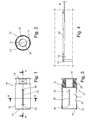
- an improved collet is shown wholly indicated with reference numeral 10.
- the collet 10 is configured to clamp the rear end of a bar inside a bar loader for lathes (not shown).
- the collet 10 comprises a body or sleeve 12, having a generic cylindrical shape and a wall thickness that is suitable for providing a substantially rigid behaviour under the action of the normal forces which are exerted on the collet 10 during use.
- the body 12 is provided with a first front open end 14, configured for inletting into it the end of a bar to be clamped, and a second rear end 16, configured for coupling with the head of a pusher of the loader.
- the body 12 of the collet 10 is moreover provided with a first internal cavity 18, placed at the first front open end 14 and able to receive and keep the end of the bar, and a second internal cavity 20, placed at the second rear end 16 and preferably threaded in order to obtain the assembly of the collet 10 on the pusher of the loader.
- the first internal cavity 18 has a diameter D that is substantially constant for the entire length L of the first internal cavity 18 itself.
- each through slot 22 is formed substantially having a longitudinal development.
- the length of each through slot 22 is preferably equal to around two thirds of the length L of the first internal cavity 18.
- Each through slot 22 is moreover preferably arranged at the central part of the first internal cavity 18.
- the surface region of the body 12 arranged around each through slot 22 is bent towards the inside of the first internal cavity 18 according to a predetermined distance K, so as to create, exclusively around each through slot 22, a corresponding deformed area 24 ( figure 5 ).
- the union of the separate deformed areas 24 generates a bottleneck on the body 12 which retains the tail-end of the bar when the latter is introduced in the collet 10.
- each deformed area 24 extends from the relative through slot 22 according to a maximum distance equal to around 1/6 of the diameter D of the first internal cavity 18.
- each deformed area 24 extends from the relative through slot 22 according to a distance in the range from 5 mm to 10 mm.
- the predetermined distance K is equal to around 1/50 of the length L of the first internal cavity 18.
- Each deformed area 24 can be obtained through pressing, for example with a roller R ( figure 5 ), before the hardening heat treatment phase and the possible tempering phase of the collet 10.
- a roller R figure 5
- the first open front end 14 has a circumferential edge that is completely closed or, in other words, each through slot 22 does not open frontally with respect to the body 12.
- the first open front end 14 of the collet 10 is perfectly cylindrical and is not deformed by the movements of the bar while working in the lathe, as occurs on the other hand, with common collets that are provided at the front with elastic sectors or fingers.
- the body 12 of the collet 10 can thus have a thickness that is also very thin, in any case guaranteeing a strong hold force and an excellent strength.
- the collet 10 With respect to collets equipped with elastic strips that project inwards with respect to the sleeve, the collet 10 according to the invention has the advantage of having a deformed area the total extension of which is much greater than that of the elastic strips.
- the arrangement of the deformed areas 24 on the surface of the body 12 guarantees a strong holding force and a low probability of breaking through fatigue of the collet 10.
- each through slot 22 respective enlarged holes 26 and 28 can be provided, substantially round shaped.
- the function of the holes 26 and 28 is that of reducing the probability of the formation of cracks on the body 12 from the ends of the through slots 22.
- each through slot 22 is preferably oriented in the axial direction of the body 12 of the collet 10.
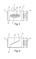
- each through slot 22 can be arranged obliquely with respect to the rotation axis of the body 12, so as to guarantee the hold on the corners of the bar (see figure 6 ).
- the number of through slots 22 to be made on the surface of the body 12 substantially depends on the dimensions of the collet 10. For example, for collets 10 having an outer diameter equal to 30 mm, three through slots 22 and three respective deformed areas 24 are provided on the body 12, disposed symmetrically and mutually spaced one from the other. For collets 10 having an outer diameter of between 30 mm and 60 mm four through slots 22 and four respective deformed areas 24 are provided, again disposed symmetrically and mutually spaced one from the other. Finally, for collets 10 having an outer diameter of above 60 mm, five through slots 22 and respective deformed areas 24 can be provided.
Landscapes
- Engineering & Computer Science (AREA)
- Mechanical Engineering (AREA)
- Turning (AREA)
- Accessories And Tools For Shearing Machines (AREA)
- Gripping On Spindles (AREA)
Applications Claiming Priority (1)
| Application Number | Priority Date | Filing Date | Title |
|---|---|---|---|
| IT000992A ITMI20110992A1 (it) | 2011-05-31 | 2011-05-31 | Pinza perfezionata per l'afferramento di barre in un caricatore per torni |
Publications (1)
| Publication Number | Publication Date |
|---|---|
| EP2529862A1 true EP2529862A1 (de) | 2012-12-05 |
Family
ID=44509977
Family Applications (1)
| Application Number | Title | Priority Date | Filing Date |
|---|---|---|---|
| EP12169859A Withdrawn EP2529862A1 (de) | 2011-05-31 | 2012-05-29 | Spannzange zur Greifung einer Stange in einer Zuführvorrichtung für automatische Drehbänke |
Country Status (2)
| Country | Link |
|---|---|
| EP (1) | EP2529862A1 (de) |
| IT (1) | ITMI20110992A1 (de) |
Citations (12)
| Publication number | Priority date | Publication date | Assignee | Title |
|---|---|---|---|---|
| US1538442A (en) * | 1924-05-31 | 1925-05-19 | Margaret Jane Mann | Feed collet |
| US1597404A (en) * | 1925-09-12 | 1926-08-24 | Jesse D Crossley | Collet |
| US1783039A (en) * | 1930-02-18 | 1930-11-25 | Frank E Green | Feed chuck |
| US2087868A (en) * | 1936-02-17 | 1937-07-20 | Baxendale Samuel | Feed collet |
| US2228863A (en) * | 1939-01-03 | 1941-01-14 | Clarence M Sutton | Feeding device |
| US2521099A (en) * | 1947-07-05 | 1950-09-05 | Irving H Sheffer | Feed collet |
| US2680623A (en) * | 1950-10-28 | 1954-06-08 | Ambrose A Hasselblad | Feed collet |
| US3672060A (en) * | 1968-07-24 | 1972-06-27 | Kaltenbach & Voigt | Dental instrument |
| US4093246A (en) | 1977-08-09 | 1978-06-06 | Frederick Goff | Universal feed finger device |
| JPS5890403A (ja) * | 1981-11-16 | 1983-05-30 | Tsuguo Shiratori | 加工素材の把持用チヤツク |
| GB2200860A (en) | 1986-11-20 | 1988-08-17 | Peter Leslie Windley | Bar stock feed device |
| ITMI990502U1 (it) * | 1999-08-06 | 2001-02-06 | Cucchi Pietro Spa | Pinza di afferramento elastico di barre in un caricatore per torni |
-
2011
- 2011-05-31 IT IT000992A patent/ITMI20110992A1/it unknown
-
2012
- 2012-05-29 EP EP12169859A patent/EP2529862A1/de not_active Withdrawn
Patent Citations (12)
| Publication number | Priority date | Publication date | Assignee | Title |
|---|---|---|---|---|
| US1538442A (en) * | 1924-05-31 | 1925-05-19 | Margaret Jane Mann | Feed collet |
| US1597404A (en) * | 1925-09-12 | 1926-08-24 | Jesse D Crossley | Collet |
| US1783039A (en) * | 1930-02-18 | 1930-11-25 | Frank E Green | Feed chuck |
| US2087868A (en) * | 1936-02-17 | 1937-07-20 | Baxendale Samuel | Feed collet |
| US2228863A (en) * | 1939-01-03 | 1941-01-14 | Clarence M Sutton | Feeding device |
| US2521099A (en) * | 1947-07-05 | 1950-09-05 | Irving H Sheffer | Feed collet |
| US2680623A (en) * | 1950-10-28 | 1954-06-08 | Ambrose A Hasselblad | Feed collet |
| US3672060A (en) * | 1968-07-24 | 1972-06-27 | Kaltenbach & Voigt | Dental instrument |
| US4093246A (en) | 1977-08-09 | 1978-06-06 | Frederick Goff | Universal feed finger device |
| JPS5890403A (ja) * | 1981-11-16 | 1983-05-30 | Tsuguo Shiratori | 加工素材の把持用チヤツク |
| GB2200860A (en) | 1986-11-20 | 1988-08-17 | Peter Leslie Windley | Bar stock feed device |
| ITMI990502U1 (it) * | 1999-08-06 | 2001-02-06 | Cucchi Pietro Spa | Pinza di afferramento elastico di barre in un caricatore per torni |
Also Published As
| Publication number | Publication date |
|---|---|
| ITMI20110992A1 (it) | 2012-12-01 |
Similar Documents
| Publication | Publication Date | Title |
|---|---|---|
| JP5895648B2 (ja) | ヘッド交換式切削工具 | |
| JP6446367B2 (ja) | プレロード型緩衝システム | |
| RU2541329C2 (ru) | Зажимной механизм режущего инструмента и способ его сборки | |
| JP2013519416A5 (de) | ||
| EP2322303B1 (de) | Bohrer | |
| WO2010045054A3 (en) | Cutting tap and method of making same | |
| KR101608006B1 (ko) | 연장 그루브를 갖는 수축 끼워맞춤 척 | |
| ES2609964T5 (es) | Método, herramienta y máquina para calibrar casquillos | |
| CN104043860A (zh) | 用于孔锯的圆柱形钻体 | |
| JP6869536B2 (ja) | 工具ホルダ | |
| JP6618010B2 (ja) | とりわけ根管に穿孔するための歯内治療器具 | |
| EP3250147B1 (de) | Scankörpersystem zur bestimmung einer positionierung und ausrichtung eines dentalimplantats | |
| JP2018192565A5 (de) | ||
| US20150314375A1 (en) | Drill chuck | |
| KR100869138B1 (ko) | 맨드렐 척 | |
| US8523471B2 (en) | Writing implement comprising a slide-on end member | |
| JP2012071391A (ja) | ヘッド交換式切削工具用ホルダおよびヘッド交換式切削工具 | |
| EP3900669A1 (de) | Verfahren zur herstellung eines interdentalreinigungsinstruments | |
| TWI387446B (zh) | 根管阻塞物移除器具 | |
| EP3520733B1 (de) | Drehschutzstruktur zur verwendung bei einem griff eines ultraschall-dentalentkalkers | |
| KR102408291B1 (ko) | 조립식 호브 | |
| CA2455517C (en) | Spacer element for a collet chuck and collet chuck | |
| RU2018143990A (ru) | Зуб с ограниченным сцеплением конической поверхности | |
| CZ2017803A3 (cs) | Upínací zařízení | |
| FI3312489T3 (fi) | Tartuntarengas |
Legal Events
| Date | Code | Title | Description |
|---|---|---|---|
| PUAI | Public reference made under article 153(3) epc to a published international application that has entered the european phase |
Free format text: ORIGINAL CODE: 0009012 |
|
| AK | Designated contracting states |
Kind code of ref document: A1 Designated state(s): AL AT BE BG CH CY CZ DE DK EE ES FI FR GB GR HR HU IE IS IT LI LT LU LV MC MK MT NL NO PL PT RO RS SE SI SK SM TR |
|
| AX | Request for extension of the european patent |
Extension state: BA ME |
|
| STAA | Information on the status of an ep patent application or granted ep patent |
Free format text: STATUS: THE APPLICATION IS DEEMED TO BE WITHDRAWN |
|
| 18D | Application deemed to be withdrawn |
Effective date: 20130606 |