EP2529887A2 - Agrégat de ponçage avec un arbre à excentrique placé dans une broche porte-meule - Google Patents
Agrégat de ponçage avec un arbre à excentrique placé dans une broche porte-meule Download PDFInfo
- Publication number
- EP2529887A2 EP2529887A2 EP12004118A EP12004118A EP2529887A2 EP 2529887 A2 EP2529887 A2 EP 2529887A2 EP 12004118 A EP12004118 A EP 12004118A EP 12004118 A EP12004118 A EP 12004118A EP 2529887 A2 EP2529887 A2 EP 2529887A2
- Authority
- EP
- European Patent Office
- Prior art keywords
- eccentric shaft
- grinding
- sanding
- grinding spindle
- unit according
- Prior art date
- Legal status (The legal status is an assumption and is not a legal conclusion. Google has not performed a legal analysis and makes no representation as to the accuracy of the status listed.)
- Granted
Links
Images



Classifications
-
- B—PERFORMING OPERATIONS; TRANSPORTING
- B24—GRINDING; POLISHING
- B24B—MACHINES, DEVICES, OR PROCESSES FOR GRINDING OR POLISHING; DRESSING OR CONDITIONING OF ABRADING SURFACES; FEEDING OF GRINDING, POLISHING, OR LAPPING AGENTS
- B24B41/00—Component parts such as frames, beds, carriages, headstocks
- B24B41/04—Headstocks; Working-spindles; Features relating thereto
- B24B41/047—Grinding heads for working on plane surfaces
Definitions
- the invention relates to a grinding unit with an eccentric shaft arranged in a grinding spindle for supporting a sanding disc bearing an abrasive.
- an electric hand grinder in which in an enclosure, an electric motor via an eccentric shaft occupied with an abrasive grinding disc placed in an oscillating oscillatory motion.
- the sanding pad is suspended on the housing so that it is mounted to oscillate transversely to the eccentric shaft.
- the center of the grinding plate is supported by means of a rolling bearing on the eccentric pin.
- the present invention is based on the problem to develop a eincicbares grinding unit, which has a simple and robust construction with a small space.
- the balanced eccentric shaft is mounted in a torsionally rigid and longitudinally displaceable manner on or in the grinding spindle.
- freely movable - sanding pad is mounted directly or by means of a sanding disk housing over at least one rolling, sliding or air bearings.
- an abrasive aggregate which i.a. suitable for processing large-area wood or wood substitute surfaces.
- the sanding pad of the grinding aggregate contributes thereto e.g. exchangeable grinding wheels, polishing wheels or corresponding brushes.
- the grinding unit adapted to the supporting machine tool via a known tool interface carries its sanding pad on a spring-mounted eccentric shaft.
- the sanding pad is in this case freely rotatably mounted on the eccentric shaft, so that the abrasive moves with respect to the eccentric shaft driving aggregate-own grinding spindle on a circular path with no or almost no self-rotation.
- the diameter of the circular path is 2 to 25 mm.
- the circular path of the tool center point is distorted in a transverse movement of the grinding spindle in a regular trajectory.
- the tool is pressed by arranged in the grinding unit spring elements against the workpiece surface to be machined.
- the spring elements such as disc springs, which are combined into stacks or packages.
- the disc springs and coil springs can be used.
- a resilient contact pressure can also be effected via a pneumatic spring.
- the weight of the eccentric shaft and the grinding plate can be sufficient to achieve the necessary contact pressure.
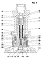
- FIGS. 1 and 2 show as a tool unit a eincicbares grinding unit, which can also be referred to as a grinding head.
- a hollow grinding spindle (10) in which an eccentric shaft (50), for example, by a stroke of 6.5 mm is mounted longitudinally displaceable and torsionally rigid.
- an eccentric shaft (50) for example, by a stroke of 6.5 mm is mounted longitudinally displaceable and torsionally rigid.
- a sanding pad housing (100) sits on whose threaded pin (113) a sanding pad (140) is arranged together with an abrasive carrier (160) and a grinding wheel (170).
- the hollow grinding spindle (10) consists essentially of a tool interface and a tubular guide section (15). It has, for example, a total length of 111 mm, with about 46% of the length attributable to the tool interface.
- the tool interface here is a hollow shank taper (11) with face abutment (HSK) according to DIN 69893.
- HSK face abutment
- Morse taper according to DIN 228, ISO steep taper according to DIN 2080 or DIN 69871, Capto ® interfaces or the like can be used.
- the guide section (15) has a radial outer wall (23) which at the end remote from the hollow shank taper (11) has a e.g. 12 mm wide, precision machined sealing seat area (24).
- the latter has an outer diameter of about 53 mm.
- the guide section (15) has on the inside a cylindrical bearing bore (16) with a flat bottom (17).
- the finely machined bearing bore (16) has an inner diameter of 38 mm.
- the center lines lie on the mantle of an abstract cylinder whose center line coincides with the center line (29) of the grinding spindle (10).
- the center line (29) is at the same time the center line of the short shaft taper (11).
- the small diameter of the cylinder counterbore (13) has e.g. a 5 mm diameter.
- the bearing bore (16) has an inner ring groove (19) for receiving a securing ring (47).
- the one-piece driving pin (30) On the bottom (17) of the bearing bore (16) by means of four countersunk screws (45) has a driving pin (30) attached.
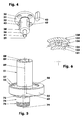
- the one-piece driving pin (30), see. FIG. 4 consists of a flange (31), a pin (33) with three longitudinal grooves (42) and a spring guide tube (36).
- the flange (31) has four through holes (32) with 90 ° counterbores.
- the centrally formed on the flange (31) pin (33), for example, at a length of 31 mm has a diameter of 18 mm, has as longitudinal grooves, for example, three circumferentially equidistantly distributed keyways (42), in each case a corresponding, made of plastic produced key (43) is pressed with a tight fit.
- a spring guide tube (36) connects, which has a length of 14 mm, for example, at a diameter of 7.1 mm.
- the spring guide tube (36) carries at its free end a 1.5 * 15 ° bevel.
- a flat collar Between the pin (33) and the spring guide tube (36) is a flat collar, which is aligned normal to the center line (29).
- the driving pin (30) has a two-stage through hole (41), the first - located in the region of the flange (31) - quarter is a cylinder counterbore.
- the eccentric shaft (50) In the guide section (15) of the grinding spindle (10) sits in a ball cage (46), the eccentric shaft (50).
- the ball cage (46) has a length of 54 mm, for example. He stores here in 24 rows 264 balls, for example, have a diameter of 4 mm.
- the eccentric shaft (50), cf. also FIG. 5 Is at the same time along the driving pin (30). It is like the grinding spindle (10) and the driving pin (30) made of the insert steel 16 MnCr5, consists of an externally machined bearing section (51), a mass balance section (53), a sealing seat portion (72), a bearing seat portion (74) and a Threaded section (75).
- the mass balancing section (53) adjoins the bearing section (51) via a ring-channel-like recess (57) which is, for example, 11 mm deep and concentric with the center line (29), cf. also Figures 2 and 3 ,
- the inner diameter of the recess (57) measures, for example 53.5 mm, so that the sealing seat portion (24) of the radial outer wall (23) of the grinding spindle (10) fits with play.
- the radial inner wall of this section (53) has an inner ring groove (58) for receiving a sealing ring in the form of an O or quad ring (59).
- the radial outer wall (23) of the mass balance section (53) has a center line (65) according to FIG. 2 offset by several millimeters, for example 3.55 mm, to the right eccentric. In the embodiment according to FIG. 3 is dispensed with an off-center outer wall.
- the local outer wall (56) is concentric with the center line (29) aligned.
- a mass balance section (54) In order to be able to function as a mass balance section (54), it has, for example, a bow-shaped or crescent-shaped unbalance recess (63). The latter is on the side of the eccentric shaft (50), on which the center line (79) is located.
- a lid such as a clamping lid (64)
- the finely machined sealing seat portion (72) has a diameter of 32 mm, for example, at a width of 6 mm.
- a planar stop collar (73) is arranged between the seal seat portion (72) and the bearing seat portion (74) .
- the eccentric shaft (50) terminates with the 7 mm threaded portion (75), eg an M25 * 1.5 thread, for receiving a shaft nut (123).
- the deep groove ball bearing (122) is axially clamped.
- the eccentric shaft (50) has a multi-stepped through-hole (80), cf. FIG. 3 and 5 whose center line (89) is congruent to the center line (29).
- the first HSK-near zone is the 26 mm long dead zone (81), for example.
- the finely worked area-wise cylindrical inner wall of this zone (81) has, for example, only 0.1 mm smaller diameter than the outer diameter of the pin (33).
- three longitudinal grooves (82) are arranged, in which the feather keys (43) of the pin (33) - to form a shaft-hub connection - are guided in sliding seats.
- feather keys (43) can be between the pin (33) and the eccentric shaft (50), for example also a wedge and hub profile with internal centering 18 * 22 * 6 according to DIN 5471 or a serrated profile 17 * 20 according to DIN 5481-1 can be used.
- the entrainment zone (81) serves a spatially subordinate, e.g. At least 6.5 mm long puncture zone (83). Their length is greater than the stroke of the eccentric shaft (50) in the grinding spindle (10).
- the puncture zone (83) ends in a plan reason.
- the next zone is the e.g. 43 mm spring return zone (84) whose diameter is e.g. 14.1 mm. It has a flat bottom that serves as the spring pad.
- the spring guide zone (84) is followed by a threaded zone (86). It is e.g. an M5 internal thread according to DIN 13-1.
- the eccentric shaft (50) to the left of the internal thread (86) has a parallel to the center line (29) extending air guide bore (77) which intersects with a short cylindrical air guide zone (85).
- the deep groove ball bearing (122) supports the sanding pad (140) by means of the substantially cylindrical sanding pad housing (100) made of an aluminum alloy.
- the latter consists of an upper and a lower part (101, 111).
- the top (101) is in the form of a sleeve with a central, single stepped bore (102).
- a lip seal (121) is pressed, the upwardly oriented Sealing lip on the sealing seat portion (72) of the eccentric shaft (50) rests.
- the cylindrical recess of the upper part (101) has, for example, an inner diameter of 47 mm.
- the lid-shaped lower part (111) carries on its flat lower end face a threaded pin (113) with an M16 thread and six holes (114) with cylinder counterbores. In these holes (114) sit the cylinder screws (125), which hold the lower part (111) in the threaded holes (103) of the upper part (101) and axially fix the rolling bearing (122) via the centering collar (112).
- the lower part (111) On the side facing the upper part (101), the lower part (111) has a short cylindrical recess (115) into which the shaft end of the eccentric shaft (50) projects with the shaft nut (123).
- the mounted sanding pad housing (100), without consideration of the threaded pin (113) has a height of e.g. 30 mm.
- FIG. 3 To FIG. 3 is the sanding pad housing (100) over the variant of the FIGS. 1 and 2 about 12 mm longer.
- a freewheel (130) On the Seating seat portion (72) of the eccentric shaft (50) sits between the stop collar (73) and the rolling bearing (122) has a freewheel (130) whose inner ring (131) on the sealing seat portion (72) and its outer ring (132) in the inner bore (102 ) of the upper housing part (101) is pressed in each case rotationally fixed.
- the freewheel (130) has 20 clamping bodies (133) which contact each other. In the contact region each clamping body (133) on both sides in the freewheeling direction of the outer ring (132) widening groove (134).
- each of the grooves (134) on both sides sits a support ring (135).
- the outer curvature of the individual clamping body (133) is offset relative to the inner curvature in the clockwise direction so that the outer ring (132) stops when the inner ring (131) rotates counterclockwise.
- the clamp bodies (133) rotate slightly counterclockwise, causing them to jam between the rings (131) and (132).
- the inner ring (131) with the outer ring (132) with.
- a clamping roller freewheel instead of the sprag freewheel (130), a clamping roller freewheel, a pawl freewheel or another comparable freewheel can also be used.
- a sanding pad (140) is screwed on the threaded pin (113) of the sanding pad housing (100).
- the sanding pad (140), cf. also FIGS. 1 and 7 is a disc in the center, for example, 14 mm thick plastic or an aluminum alloy, which tapers between a diameter of 63 mm and its outer diameter of 115 mm with an angle of 20 degrees. It has a central internal thread (142), cf. FIG. 3 , over which it is screwed onto the threaded pin (113) of the sanding pad housing (100).
- the upper face of the sanding pad (140) has a 0.5 mm deep intake turn (169) with a diameter of 50 mm.
- the center line (29) for example, eight continuous oblique holes (143), see. FIG. 7 arranged in a 45-degree angle graduation. They have a diameter of 10 mm.
- the center lines of the oblique holes (143) lie on an imaginary cone whose cone point, as seen in the direction of abrasive (170), about 90 mm in front of the abrasive carrier (160) facing end face (141) on the center line (29).
- the cone angle of the imaginary cone is 40 degrees.
- annular channel (145) Between the oblique holes (143) and the internal thread (142) is a 9 mm deep and 15 mm wide annular channel (145), whose largest diameter measures 52 mm.
- the annular channel (145) is incorporated from the lower end face (141) into the sanding pad (140).
- the end face (141) has four more, but smaller, decentralized annular channels (146) lying on a circle whose diameter is 85 mm.
- Each of these annular channels (146), which lies at a pitch of 90 degrees between each two inclined holes (143), has a depth of 5 mm, a maximum diameter of 21 mm and a width of 6 mm.
- an M4 threaded hole (147) In the center of each annular channel (146) is an M4 threaded hole (147).
- Eight continuous longitudinal bores (164) are in a 45-degree angular pitch on a circle with a diameter of 65 mm arranged. They each have a diameter of 10 mm. If the abrasive carrier (160) for in the variant after FIG. 3 used, he also has a central bore (165).
- the upper side (161) of the abrasive carrier (160) has four annular ribs (162) which are arranged in the decentralized annular channels (146) of the Sanding pad (140) fit.
- the inner flanks of the annular webs (162) come to rest against the inner flanks of the annular channels (146).
- the abrasive carrier (160) In the lower side (167) of the abrasive carrier (160), four fixing holes (163) provided with cylinder countersinks are arranged. The center lines of these bores (163) are aligned with the center lines of the ring webs (162) arranged on the upper side (161).
- the underside (167) of the abrasive carrier (160) is coated, for example, with a fabric having a plurality of small barbs like a hook and loop fastener.
- the abrasive carrier (160) rests with its upper side (161) on the end face (141) of the grinding disc (140), wherein the annular ribs (162) center in the decentralized annular channels (146).
- the S-abrasive carrier (160) is fastened with four Allen screws (168), cf. FIG. 1 , bolted to the sanding pad (140).
- the abrasive carrier (160) On the underside (167) of the abrasive carrier (160) is after the FIGS. 1 to 3 arranged as an abrasive or tool, for example, a circular, flexible grinding wheel (170). It has matching to the corresponding abrasive carrier (160) a plurality of holes corresponding to the local bores (164, 165).
- the abrasive backing (160) facing the abrasive backing carries a thin fleece having a plurality of woven, closed, small loops in which the barbs of the underside coating of the abrasive backing (160) interlock.
- a large number of abrasive grains of comparable grain size is incorporated.
- the sanding pad (140) of the variant according to the FIGS. 1 and 2 eg in a spherical roller bearing according to DIN 635, a self-aligning ball bearing according to DIN 630, a spherical roller bearing according to DIN 635, a comparable sliding bearing with spherical sliding surfaces or the like are stored.
- a pressure piece can be centrally arranged, whose - due to the between the parts (50) and (100 ) existing relative movement wear-resistant - detent ball engages in a direction of the center line (79) normally aligned sanding pad (140) in a corresponding recess recess.
- the machine tool After replacing the equipped with a grinding wheel (170) grinding aggregate in the main spindle of the machine tool, such as a woodworking machine, this is rotated.
- a speed for example, 50 to 300 rpm initially provided.
- the mounted on the eccentric shaft (50) sanding plate (140) rotates after a short time with the speed of the eccentric shaft (50).
- the grinding unit is moved to the workpiece surface to be machined as long moved in the normal direction until the grinding wheel (170) contacts them.
- the sanding pad (140) is decelerated.
- the grinding spindle (10) is delivered in the tenth millimeter to millimeter range normal to the workpiece surface, so that a defined pressure force results from the plate springs (127) arranged between the driving pin (30) and the eccentric shaft (50).
- the eccentric shaft (50) slides almost free of play over the ball cage (46) deeper into the bearing bore (16) of the grinding spindle (10).
- the speed of the grinding spindle (10) is increased to a certain operating speed.
- the latter is depending on the application in the range of 1000 to 10,000 rpm.
- the center line (29) of the grinding unit stationary to the workpiece surface the center of the grinding wheel (170) describes a circular path with a radius corresponding to the eccentricity (76) of the eccentric portion (71) of the eccentric shaft (50). Since in this case the sanding pad (140) has no or almost no inherent rotation relative to the machine tool or relative to the stationary housing of the main spindle, the eccentric section (71) rotates in the sanding disk housing (100) at full or almost full operating speed.
- the center of the grinding wheel describes a trajectory, for example, represents an oblique projection of a helix or one between two boundary lines progressive oscillating curve.
- the two boundary lines have a distance of twice the eccentricity.
- FIG. 3 For example, with a right-handed grinding spindle (10), it shows the behavior described above. However, if the grinding spindle (10) is reversed to a left turn, the freewheel (130) couples the sanding pad housing (100) to the eccentric shaft (50). Thus, the sanding pad (140) rotates synchronously with the grinding spindle (10). In a regular machining cycle, for example, the grinding spindle (10) is now operated 95 to 99.9% of the grinding time with operating speed in the clockwise direction, wherein the freewheel (130) has no clamping action.
- the remaining grinding time rotates the grinding spindle (10) in the counterclockwise direction - ie in the opposite direction - at a greatly reduced speed, eg 50 to 300 rpm.
- the sanding pad (140) inevitably changes its angular position oriented around the center line (29) relative to the housing of the machine tool main spindle, whereby, inter alia, an undesired recurring abrasive structure is avoided on the workpiece surface.
- the variant after FIG. 3 is additionally equipped with a compressed air supply.
- the compressed air is supplied to the machine side of the machine tool main spindle the adapter cavity (12) of the hollow shaft short-taper (11). From there, the compressed air passes through the cylinder counterbore (13) into the through hole (41) of the driving pin (30). Latter is connected via the transverse groove (35) and the longitudinal groove (34) with the spring guide zone (84). The compressed air flows there via the disc spring bores along the retaining screw (87) into the air guiding zone (85).
- the air guide zone (85) communicates with the bore (165) of the abrasive carrier (160) and the corresponding bore of the abrasive wheel (170) via the air guide bore (77) and the bore (117).
- the compressed air exiting centrally from the grinding wheel (170) flows radially along the workpiece surface in order, for example, to reach the rear side of the grinding plate (140) via the bores (164) and (143), from where it is suctioned off on the machine side.
Landscapes
- Engineering & Computer Science (AREA)
- Mechanical Engineering (AREA)
- Finish Polishing, Edge Sharpening, And Grinding By Specific Grinding Devices (AREA)
- Polishing Bodies And Polishing Tools (AREA)
- Constituent Portions Of Griding Lathes, Driving, Sensing And Control (AREA)
Applications Claiming Priority (1)
| Application Number | Priority Date | Filing Date | Title |
|---|---|---|---|
| DE201110103559 DE102011103559B3 (de) | 2011-05-30 | 2011-05-30 | Schleifaggregat mit einer in einer Schleifspindel angeordneten Exzenterwelle |
Publications (3)
| Publication Number | Publication Date |
|---|---|
| EP2529887A2 true EP2529887A2 (fr) | 2012-12-05 |
| EP2529887A3 EP2529887A3 (fr) | 2014-07-02 |
| EP2529887B1 EP2529887B1 (fr) | 2015-12-16 |
Family
ID=46208289
Family Applications (1)
| Application Number | Title | Priority Date | Filing Date |
|---|---|---|---|
| EP12004118.1A Active EP2529887B1 (fr) | 2011-05-30 | 2012-05-29 | Agrégat de ponçage avec un arbre à excentrique placé dans une broche porte-meule |
Country Status (2)
| Country | Link |
|---|---|
| EP (1) | EP2529887B1 (fr) |
| DE (1) | DE102011103559B3 (fr) |
Cited By (7)
| Publication number | Priority date | Publication date | Assignee | Title |
|---|---|---|---|---|
| EP3238878A1 (fr) * | 2016-04-27 | 2017-11-01 | Guido Valentini | Machine outil de meulage ou de polissage guidée à la main ou portative |
| CN107457690A (zh) * | 2017-08-31 | 2017-12-12 | 广州市永合祥自动化设备科技有限公司 | 研磨抛光机及其辅助机构 |
| WO2019041392A1 (fr) * | 2017-08-31 | 2019-03-07 | 广州市永合祥自动化设备科技有限公司 | Machine de polissage et son mécanisme de positionnement en rotation |
| WO2019041393A1 (fr) * | 2017-08-31 | 2019-03-07 | 广州市永合祥自动化设备科技有限公司 | Mécanisme de rodage et de polissage |
| EP3406401A4 (fr) * | 2016-01-18 | 2019-07-03 | Xebec Technology Co., Ltd. | Procédé d'usinage de pièce de travail, brosse de machine de polissage, et porte-outil |
| WO2020257918A1 (fr) * | 2019-06-25 | 2020-12-30 | C.M.E. Blasting & Mining Equipment Ltd. | Outil de broyage pour broyer des boutons sur un taillant de fleuret |
| CN121374301A (zh) * | 2025-12-24 | 2026-01-23 | 中国铁建重工集团股份有限公司 | 一种主轴承套圈平面软带打磨方法 |
Families Citing this family (2)
| Publication number | Priority date | Publication date | Assignee | Title |
|---|---|---|---|---|
| DE102015121305A1 (de) * | 2015-12-08 | 2017-06-08 | Festool Gmbh | Hand-Werkzeugmaschine |
| WO2023146485A1 (fr) * | 2022-01-25 | 2023-08-03 | Silica-Gem Turizm Sanayi Ticaret Limited Sirketi | Configuration d'arbre conique dans des machines de corrosion et de polissage |
Citations (1)
| Publication number | Priority date | Publication date | Assignee | Title |
|---|---|---|---|---|
| DE19608969A1 (de) | 1996-03-08 | 1997-09-11 | Bosch Gmbh Robert | Elektrische Handschleifmaschine |
Family Cites Families (6)
| Publication number | Priority date | Publication date | Assignee | Title |
|---|---|---|---|---|
| US5947804A (en) * | 1998-04-27 | 1999-09-07 | Ryobi North America, Inc. | Adjustable eccentricity orbital tool |
| DE19820873A1 (de) * | 1998-05-09 | 1999-11-11 | Bosch Gmbh Robert | Elektrohandwerkzeugmaschine, insbesondere Handschleifmaschine |
| DE29903443U1 (de) * | 1999-02-26 | 2000-06-29 | Gisbert Brinkschulte GmbH & Co. KG Import - Export, 28359 Bremen | Polier- und Schleifmaschine |
| DE10142557A1 (de) * | 2001-08-30 | 2003-03-20 | Hilti Ag | Handgeführter Exzenterschleifer |
| DE102006056179A1 (de) * | 2006-11-27 | 2008-06-05 | Bernd Luckas | Schleifkopf zur Verwendung an einem Roboter |
| ES2332568B1 (es) * | 2008-07-23 | 2011-04-18 | Airbus Operations, S.L. | Sistema de repasado orbital post-afeitado de remaches. |
-
2011
- 2011-05-30 DE DE201110103559 patent/DE102011103559B3/de not_active Expired - Fee Related
-
2012
- 2012-05-29 EP EP12004118.1A patent/EP2529887B1/fr active Active
Patent Citations (1)
| Publication number | Priority date | Publication date | Assignee | Title |
|---|---|---|---|---|
| DE19608969A1 (de) | 1996-03-08 | 1997-09-11 | Bosch Gmbh Robert | Elektrische Handschleifmaschine |
Cited By (10)
| Publication number | Priority date | Publication date | Assignee | Title |
|---|---|---|---|---|
| EP3406401A4 (fr) * | 2016-01-18 | 2019-07-03 | Xebec Technology Co., Ltd. | Procédé d'usinage de pièce de travail, brosse de machine de polissage, et porte-outil |
| EP3238878A1 (fr) * | 2016-04-27 | 2017-11-01 | Guido Valentini | Machine outil de meulage ou de polissage guidée à la main ou portative |
| CN107309753A (zh) * | 2016-04-27 | 2017-11-03 | 盖多·瓦伦蒂尼 | 手持式或手导引式研磨或抛光机械工具 |
| CN107457690A (zh) * | 2017-08-31 | 2017-12-12 | 广州市永合祥自动化设备科技有限公司 | 研磨抛光机及其辅助机构 |
| CN107457690B (zh) * | 2017-08-31 | 2018-06-29 | 广州市永合祥自动化设备科技有限公司 | 研磨抛光机及其辅助机构 |
| WO2019041392A1 (fr) * | 2017-08-31 | 2019-03-07 | 广州市永合祥自动化设备科技有限公司 | Machine de polissage et son mécanisme de positionnement en rotation |
| WO2019041393A1 (fr) * | 2017-08-31 | 2019-03-07 | 广州市永合祥自动化设备科技有限公司 | Mécanisme de rodage et de polissage |
| WO2019041391A1 (fr) * | 2017-08-31 | 2019-03-07 | 广州市永合祥自动化设备科技有限公司 | Machine de rodage et de polissage et son mécanisme auxiliaire |
| WO2020257918A1 (fr) * | 2019-06-25 | 2020-12-30 | C.M.E. Blasting & Mining Equipment Ltd. | Outil de broyage pour broyer des boutons sur un taillant de fleuret |
| CN121374301A (zh) * | 2025-12-24 | 2026-01-23 | 中国铁建重工集团股份有限公司 | 一种主轴承套圈平面软带打磨方法 |
Also Published As
| Publication number | Publication date |
|---|---|
| DE102011103559B3 (de) | 2012-11-15 |
| EP2529887B1 (fr) | 2015-12-16 |
| EP2529887A3 (fr) | 2014-07-02 |
Similar Documents
| Publication | Publication Date | Title |
|---|---|---|
| EP2529887B1 (fr) | Agrégat de ponçage avec un arbre à excentrique placé dans une broche porte-meule | |
| EP2029305A2 (fr) | Outil de machine et bague coupante pour outil de machine | |
| DE102014223038B4 (de) | Vorrichtung und Verfahren zum Aufrauen einer Substratoberfläche | |
| DE2909227A1 (de) | Einrichtung an werkzeugmaschinen | |
| DE112006000212B4 (de) | Gleitführungsmechanismus und elektrische Bohreinheit | |
| WO2015185026A1 (fr) | Outil de fraisage | |
| EP2492072B1 (fr) | Dispositif de traitement doté d'un rouleau palpeur | |
| EP3164252B1 (fr) | Dispositif d'entraînement en oscillation | |
| EP2072201A1 (fr) | Palpeur d'angle | |
| WO2011124458A1 (fr) | Outil motorisé portable pourvu d'un dispositif de compensation de déséquilibre et d'un dispositif de serrage pour un moyen de travail à symétrie de rotation | |
| DE102021126601A1 (de) | Vorrichtung zur spanabhebenden Metallbearbeitung und Verfahren zum Gewindefräsen | |
| EP2041452B1 (fr) | Dispositif d'équilibrage et procédé | |
| EP3090831B1 (fr) | Système de changement rapide d'outil comprenant un dispositif de guidage de copeaux | |
| EP1757392B1 (fr) | Mandrin à diaphragme | |
| DE2626912A1 (de) | Maschine zur bearbeitung von werkstuecken | |
| DE4008350C2 (de) | Modular aufgebautes Schaftwerkzeug für die Innen- und/oder Außenbearbeitung von Werkstückoberflächen | |
| DE19539082C2 (de) | Werkzeugträger für Rundbacken-Walzwerkzeuge für Rundbacken-Querwalzmaschinen | |
| DE19934375B4 (de) | Spannfutter | |
| EP0500827A1 (fr) | Dispositif pour la determination et le controle de l'avance sur un appareil d'usinage de siege de soupape | |
| DE102020123783B4 (de) | Vorrichtung zum zerspanenden Bearbeiten | |
| DE102017010096A1 (de) | Werkzeughalter mit elastischer Ausgleichskupplung | |
| DD238555A1 (de) | Backenfutter mit im futtergehaeuse durch getrieberaeder angetriebener planspirale | |
| EP2014418A1 (fr) | Outil de meulage pour machine | |
| EP0067402B1 (fr) | Tête porte-meule pour roche dure | |
| DE19549381C2 (de) | Schleifwerkzeug |
Legal Events
| Date | Code | Title | Description |
|---|---|---|---|
| PUAI | Public reference made under article 153(3) epc to a published international application that has entered the european phase |
Free format text: ORIGINAL CODE: 0009012 |
|
| AK | Designated contracting states |
Kind code of ref document: A2 Designated state(s): AL AT BE BG CH CY CZ DE DK EE ES FI FR GB GR HR HU IE IS IT LI LT LU LV MC MK MT NL NO PL PT RO RS SE SI SK SM TR |
|
| AX | Request for extension of the european patent |
Extension state: BA ME |
|
| PUAL | Search report despatched |
Free format text: ORIGINAL CODE: 0009013 |
|
| AK | Designated contracting states |
Kind code of ref document: A3 Designated state(s): AL AT BE BG CH CY CZ DE DK EE ES FI FR GB GR HR HU IE IS IT LI LT LU LV MC MK MT NL NO PL PT RO RS SE SI SK SM TR |
|
| AX | Request for extension of the european patent |
Extension state: BA ME |
|
| RIC1 | Information provided on ipc code assigned before grant |
Ipc: B24B 41/047 20060101AFI20140527BHEP Ipc: B24B 23/03 20060101ALI20140527BHEP Ipc: B24B 23/04 20060101ALI20140527BHEP |
|
| 17P | Request for examination filed |
Effective date: 20141205 |
|
| RBV | Designated contracting states (corrected) |
Designated state(s): AL AT BE BG CH CY CZ DE DK EE ES FI FR GB GR HR HU IE IS IT LI LT LU LV MC MK MT NL NO PL PT RO RS SE SI SK SM TR |
|
| GRAP | Despatch of communication of intention to grant a patent |
Free format text: ORIGINAL CODE: EPIDOSNIGR1 |
|
| INTG | Intention to grant announced |
Effective date: 20150731 |
|
| GRAS | Grant fee paid |
Free format text: ORIGINAL CODE: EPIDOSNIGR3 |
|
| GRAA | (expected) grant |
Free format text: ORIGINAL CODE: 0009210 |
|
| AK | Designated contracting states |
Kind code of ref document: B1 Designated state(s): AL AT BE BG CH CY CZ DE DK EE ES FI FR GB GR HR HU IE IS IT LI LT LU LV MC MK MT NL NO PL PT RO RS SE SI SK SM TR |
|
| REG | Reference to a national code |
Ref country code: GB Ref legal event code: FG4D Free format text: NOT ENGLISH |
|
| REG | Reference to a national code |
Ref country code: CH Ref legal event code: EP |
|
| REG | Reference to a national code |
Ref country code: IE Ref legal event code: FG4D Free format text: LANGUAGE OF EP DOCUMENT: GERMAN |
|
| REG | Reference to a national code |
Ref country code: AT Ref legal event code: REF Ref document number: 765302 Country of ref document: AT Kind code of ref document: T Effective date: 20160115 |
|
| REG | Reference to a national code |
Ref country code: DE Ref legal event code: R096 Ref document number: 502012005468 Country of ref document: DE |
|
| REG | Reference to a national code |
Ref country code: NL Ref legal event code: MP Effective date: 20151216 |
|
| REG | Reference to a national code |
Ref country code: LT Ref legal event code: MG4D |
|
| PG25 | Lapsed in a contracting state [announced via postgrant information from national office to epo] |
Ref country code: LT Free format text: LAPSE BECAUSE OF FAILURE TO SUBMIT A TRANSLATION OF THE DESCRIPTION OR TO PAY THE FEE WITHIN THE PRESCRIBED TIME-LIMIT Effective date: 20151216 Ref country code: NO Free format text: LAPSE BECAUSE OF FAILURE TO SUBMIT A TRANSLATION OF THE DESCRIPTION OR TO PAY THE FEE WITHIN THE PRESCRIBED TIME-LIMIT Effective date: 20160316 Ref country code: HR Free format text: LAPSE BECAUSE OF FAILURE TO SUBMIT A TRANSLATION OF THE DESCRIPTION OR TO PAY THE FEE WITHIN THE PRESCRIBED TIME-LIMIT Effective date: 20151216 |
|
| PG25 | Lapsed in a contracting state [announced via postgrant information from national office to epo] |
Ref country code: FI Free format text: LAPSE BECAUSE OF FAILURE TO SUBMIT A TRANSLATION OF THE DESCRIPTION OR TO PAY THE FEE WITHIN THE PRESCRIBED TIME-LIMIT Effective date: 20151216 Ref country code: NL Free format text: LAPSE BECAUSE OF FAILURE TO SUBMIT A TRANSLATION OF THE DESCRIPTION OR TO PAY THE FEE WITHIN THE PRESCRIBED TIME-LIMIT Effective date: 20151216 Ref country code: GR Free format text: LAPSE BECAUSE OF FAILURE TO SUBMIT A TRANSLATION OF THE DESCRIPTION OR TO PAY THE FEE WITHIN THE PRESCRIBED TIME-LIMIT Effective date: 20160317 Ref country code: LV Free format text: LAPSE BECAUSE OF FAILURE TO SUBMIT A TRANSLATION OF THE DESCRIPTION OR TO PAY THE FEE WITHIN THE PRESCRIBED TIME-LIMIT Effective date: 20151216 Ref country code: RS Free format text: LAPSE BECAUSE OF FAILURE TO SUBMIT A TRANSLATION OF THE DESCRIPTION OR TO PAY THE FEE WITHIN THE PRESCRIBED TIME-LIMIT Effective date: 20151216 Ref country code: SE Free format text: LAPSE BECAUSE OF FAILURE TO SUBMIT A TRANSLATION OF THE DESCRIPTION OR TO PAY THE FEE WITHIN THE PRESCRIBED TIME-LIMIT Effective date: 20151216 |
|
| PG25 | Lapsed in a contracting state [announced via postgrant information from national office to epo] |
Ref country code: CZ Free format text: LAPSE BECAUSE OF FAILURE TO SUBMIT A TRANSLATION OF THE DESCRIPTION OR TO PAY THE FEE WITHIN THE PRESCRIBED TIME-LIMIT Effective date: 20151216 Ref country code: ES Free format text: LAPSE BECAUSE OF FAILURE TO SUBMIT A TRANSLATION OF THE DESCRIPTION OR TO PAY THE FEE WITHIN THE PRESCRIBED TIME-LIMIT Effective date: 20151216 |
|
| PG25 | Lapsed in a contracting state [announced via postgrant information from national office to epo] |
Ref country code: IS Free format text: LAPSE BECAUSE OF FAILURE TO SUBMIT A TRANSLATION OF THE DESCRIPTION OR TO PAY THE FEE WITHIN THE PRESCRIBED TIME-LIMIT Effective date: 20160416 Ref country code: SM Free format text: LAPSE BECAUSE OF FAILURE TO SUBMIT A TRANSLATION OF THE DESCRIPTION OR TO PAY THE FEE WITHIN THE PRESCRIBED TIME-LIMIT Effective date: 20151216 Ref country code: BE Free format text: LAPSE BECAUSE OF NON-PAYMENT OF DUE FEES Effective date: 20160531 Ref country code: PT Free format text: LAPSE BECAUSE OF FAILURE TO SUBMIT A TRANSLATION OF THE DESCRIPTION OR TO PAY THE FEE WITHIN THE PRESCRIBED TIME-LIMIT Effective date: 20160418 Ref country code: EE Free format text: LAPSE BECAUSE OF FAILURE TO SUBMIT A TRANSLATION OF THE DESCRIPTION OR TO PAY THE FEE WITHIN THE PRESCRIBED TIME-LIMIT Effective date: 20151216 Ref country code: SK Free format text: LAPSE BECAUSE OF FAILURE TO SUBMIT A TRANSLATION OF THE DESCRIPTION OR TO PAY THE FEE WITHIN THE PRESCRIBED TIME-LIMIT Effective date: 20151216 Ref country code: RO Free format text: LAPSE BECAUSE OF FAILURE TO SUBMIT A TRANSLATION OF THE DESCRIPTION OR TO PAY THE FEE WITHIN THE PRESCRIBED TIME-LIMIT Effective date: 20151216 |
|
| REG | Reference to a national code |
Ref country code: DE Ref legal event code: R097 Ref document number: 502012005468 Country of ref document: DE |
|
| PLBE | No opposition filed within time limit |
Free format text: ORIGINAL CODE: 0009261 |
|
| STAA | Information on the status of an ep patent application or granted ep patent |
Free format text: STATUS: NO OPPOSITION FILED WITHIN TIME LIMIT |
|
| PG25 | Lapsed in a contracting state [announced via postgrant information from national office to epo] |
Ref country code: DK Free format text: LAPSE BECAUSE OF FAILURE TO SUBMIT A TRANSLATION OF THE DESCRIPTION OR TO PAY THE FEE WITHIN THE PRESCRIBED TIME-LIMIT Effective date: 20151216 Ref country code: PL Free format text: LAPSE BECAUSE OF FAILURE TO SUBMIT A TRANSLATION OF THE DESCRIPTION OR TO PAY THE FEE WITHIN THE PRESCRIBED TIME-LIMIT Effective date: 20151216 |
|
| 26N | No opposition filed |
Effective date: 20160919 |
|
| PG25 | Lapsed in a contracting state [announced via postgrant information from national office to epo] |
Ref country code: LU Free format text: LAPSE BECAUSE OF FAILURE TO SUBMIT A TRANSLATION OF THE DESCRIPTION OR TO PAY THE FEE WITHIN THE PRESCRIBED TIME-LIMIT Effective date: 20160529 |
|
| REG | Reference to a national code |
Ref country code: CH Ref legal event code: PL |
|
| GBPC | Gb: european patent ceased through non-payment of renewal fee |
Effective date: 20160529 |
|
| PG25 | Lapsed in a contracting state [announced via postgrant information from national office to epo] |
Ref country code: CH Free format text: LAPSE BECAUSE OF NON-PAYMENT OF DUE FEES Effective date: 20160531 Ref country code: LI Free format text: LAPSE BECAUSE OF NON-PAYMENT OF DUE FEES Effective date: 20160531 |
|
| REG | Reference to a national code |
Ref country code: IE Ref legal event code: MM4A |
|
| PG25 | Lapsed in a contracting state [announced via postgrant information from national office to epo] |
Ref country code: SI Free format text: LAPSE BECAUSE OF FAILURE TO SUBMIT A TRANSLATION OF THE DESCRIPTION OR TO PAY THE FEE WITHIN THE PRESCRIBED TIME-LIMIT Effective date: 20151216 |
|
| REG | Reference to a national code |
Ref country code: FR Ref legal event code: ST Effective date: 20170131 |
|
| PG25 | Lapsed in a contracting state [announced via postgrant information from national office to epo] |
Ref country code: FR Free format text: LAPSE BECAUSE OF NON-PAYMENT OF DUE FEES Effective date: 20160531 |
|
| PG25 | Lapsed in a contracting state [announced via postgrant information from national office to epo] |
Ref country code: IE Free format text: LAPSE BECAUSE OF NON-PAYMENT OF DUE FEES Effective date: 20160529 Ref country code: GB Free format text: LAPSE BECAUSE OF NON-PAYMENT OF DUE FEES Effective date: 20160529 |
|
| PG25 | Lapsed in a contracting state [announced via postgrant information from national office to epo] |
Ref country code: CY Free format text: LAPSE BECAUSE OF FAILURE TO SUBMIT A TRANSLATION OF THE DESCRIPTION OR TO PAY THE FEE WITHIN THE PRESCRIBED TIME-LIMIT Effective date: 20151216 Ref country code: HU Free format text: LAPSE BECAUSE OF FAILURE TO SUBMIT A TRANSLATION OF THE DESCRIPTION OR TO PAY THE FEE WITHIN THE PRESCRIBED TIME-LIMIT; INVALID AB INITIO Effective date: 20120529 |
|
| PG25 | Lapsed in a contracting state [announced via postgrant information from national office to epo] |
Ref country code: MT Free format text: LAPSE BECAUSE OF FAILURE TO SUBMIT A TRANSLATION OF THE DESCRIPTION OR TO PAY THE FEE WITHIN THE PRESCRIBED TIME-LIMIT Effective date: 20151216 Ref country code: MC Free format text: LAPSE BECAUSE OF FAILURE TO SUBMIT A TRANSLATION OF THE DESCRIPTION OR TO PAY THE FEE WITHIN THE PRESCRIBED TIME-LIMIT Effective date: 20151216 Ref country code: TR Free format text: LAPSE BECAUSE OF FAILURE TO SUBMIT A TRANSLATION OF THE DESCRIPTION OR TO PAY THE FEE WITHIN THE PRESCRIBED TIME-LIMIT Effective date: 20151216 Ref country code: MK Free format text: LAPSE BECAUSE OF FAILURE TO SUBMIT A TRANSLATION OF THE DESCRIPTION OR TO PAY THE FEE WITHIN THE PRESCRIBED TIME-LIMIT Effective date: 20151216 |
|
| REG | Reference to a national code |
Ref country code: DE Ref legal event code: R082 Ref document number: 502012005468 Country of ref document: DE Representative=s name: HOFFMANN - EITLE PATENT- UND RECHTSANWAELTE PA, DE |
|
| REG | Reference to a national code |
Ref country code: AT Ref legal event code: MM01 Ref document number: 765302 Country of ref document: AT Kind code of ref document: T Effective date: 20170529 |
|
| PG25 | Lapsed in a contracting state [announced via postgrant information from national office to epo] |
Ref country code: BG Free format text: LAPSE BECAUSE OF FAILURE TO SUBMIT A TRANSLATION OF THE DESCRIPTION OR TO PAY THE FEE WITHIN THE PRESCRIBED TIME-LIMIT Effective date: 20151216 |
|
| PG25 | Lapsed in a contracting state [announced via postgrant information from national office to epo] |
Ref country code: AT Free format text: LAPSE BECAUSE OF NON-PAYMENT OF DUE FEES Effective date: 20170529 |
|
| PG25 | Lapsed in a contracting state [announced via postgrant information from national office to epo] |
Ref country code: AL Free format text: LAPSE BECAUSE OF FAILURE TO SUBMIT A TRANSLATION OF THE DESCRIPTION OR TO PAY THE FEE WITHIN THE PRESCRIBED TIME-LIMIT Effective date: 20151216 |
|
| P01 | Opt-out of the competence of the unified patent court (upc) registered |
Effective date: 20230606 |
|
| PGFP | Annual fee paid to national office [announced via postgrant information from national office to epo] |
Ref country code: IT Payment date: 20240523 Year of fee payment: 13 |
|
| PGFP | Annual fee paid to national office [announced via postgrant information from national office to epo] |
Ref country code: DE Payment date: 20250521 Year of fee payment: 14 |
|
| PG25 | Lapsed in a contracting state [announced via postgrant information from national office to epo] |
Ref country code: IT Free format text: LAPSE BECAUSE OF NON-PAYMENT OF DUE FEES Effective date: 20250529 |