EP2529938A2 - Drucker und Steuerungsverfahren dafür - Google Patents
Drucker und Steuerungsverfahren dafür Download PDFInfo
- Publication number
- EP2529938A2 EP2529938A2 EP12169771A EP12169771A EP2529938A2 EP 2529938 A2 EP2529938 A2 EP 2529938A2 EP 12169771 A EP12169771 A EP 12169771A EP 12169771 A EP12169771 A EP 12169771A EP 2529938 A2 EP2529938 A2 EP 2529938A2
- Authority
- EP
- European Patent Office
- Prior art keywords
- recording paper
- bezel
- sensor
- presenter unit
- printer
- Prior art date
- Legal status (The legal status is an assumption and is not a legal conclusion. Google has not performed a legal analysis and makes no representation as to the accuracy of the status listed.)
- Withdrawn
Links
Images








Classifications
-
- B—PERFORMING OPERATIONS; TRANSPORTING
- B41—PRINTING; LINING MACHINES; TYPEWRITERS; STAMPS
- B41J—TYPEWRITERS; SELECTIVE PRINTING MECHANISMS, i.e. MECHANISMS PRINTING OTHERWISE THAN FROM A FORME; CORRECTION OF TYPOGRAPHICAL ERRORS
- B41J11/00—Devices or arrangements of selective printing mechanisms, e.g. ink-jet printers or thermal printers, for supporting or handling copy material in sheet or web form
- B41J11/66—Applications of cutting devices
-
- B—PERFORMING OPERATIONS; TRANSPORTING
- B41—PRINTING; LINING MACHINES; TYPEWRITERS; STAMPS
- B41J—TYPEWRITERS; SELECTIVE PRINTING MECHANISMS, i.e. MECHANISMS PRINTING OTHERWISE THAN FROM A FORME; CORRECTION OF TYPOGRAPHICAL ERRORS
- B41J15/00—Devices or arrangements of selective printing mechanisms, e.g. ink-jet printers or thermal printers, specially adapted for supporting or handling copy material in continuous form, e.g. webs
- B41J15/04—Supporting, feeding, or guiding devices; Mountings for web rolls or spindles
-
- B—PERFORMING OPERATIONS; TRANSPORTING
- B41—PRINTING; LINING MACHINES; TYPEWRITERS; STAMPS
- B41J—TYPEWRITERS; SELECTIVE PRINTING MECHANISMS, i.e. MECHANISMS PRINTING OTHERWISE THAN FROM A FORME; CORRECTION OF TYPOGRAPHICAL ERRORS
- B41J11/00—Devices or arrangements of selective printing mechanisms, e.g. ink-jet printers or thermal printers, for supporting or handling copy material in sheet or web form
- B41J11/66—Applications of cutting devices
- B41J11/70—Applications of cutting devices cutting perpendicular to the direction of paper feed
-
- B—PERFORMING OPERATIONS; TRANSPORTING
- B41—PRINTING; LINING MACHINES; TYPEWRITERS; STAMPS
- B41J—TYPEWRITERS; SELECTIVE PRINTING MECHANISMS, i.e. MECHANISMS PRINTING OTHERWISE THAN FROM A FORME; CORRECTION OF TYPOGRAPHICAL ERRORS
- B41J13/00—Devices or arrangements of selective printing mechanisms, e.g. ink-jet printers or thermal printers, specially adapted for supporting or handling copy material in short lengths, e.g. sheets
- B41J13/10—Sheet holders, retainers, movable guides, or stationary guides
- B41J13/106—Sheet holders, retainers, movable guides, or stationary guides for the sheet output section
-
- B—PERFORMING OPERATIONS; TRANSPORTING
- B41—PRINTING; LINING MACHINES; TYPEWRITERS; STAMPS
- B41J—TYPEWRITERS; SELECTIVE PRINTING MECHANISMS, i.e. MECHANISMS PRINTING OTHERWISE THAN FROM A FORME; CORRECTION OF TYPOGRAPHICAL ERRORS
- B41J15/00—Devices or arrangements of selective printing mechanisms, e.g. ink-jet printers or thermal printers, specially adapted for supporting or handling copy material in continuous form, e.g. webs
-
- B—PERFORMING OPERATIONS; TRANSPORTING
- B41—PRINTING; LINING MACHINES; TYPEWRITERS; STAMPS
- B41J—TYPEWRITERS; SELECTIVE PRINTING MECHANISMS, i.e. MECHANISMS PRINTING OTHERWISE THAN FROM A FORME; CORRECTION OF TYPOGRAPHICAL ERRORS
- B41J2/00—Typewriters or selective printing mechanisms characterised by the printing or marking process for which they are designed
- B41J2/315—Typewriters or selective printing mechanisms characterised by the printing or marking process for which they are designed characterised by selective application of heat to a heat sensitive printing or impression-transfer material
- B41J2/32—Typewriters or selective printing mechanisms characterised by the printing or marking process for which they are designed characterised by selective application of heat to a heat sensitive printing or impression-transfer material using thermal heads
-
- B—PERFORMING OPERATIONS; TRANSPORTING
- B41—PRINTING; LINING MACHINES; TYPEWRITERS; STAMPS
- B41J—TYPEWRITERS; SELECTIVE PRINTING MECHANISMS, i.e. MECHANISMS PRINTING OTHERWISE THAN FROM A FORME; CORRECTION OF TYPOGRAPHICAL ERRORS
- B41J29/00—Details of, or accessories for, typewriters or selective printing mechanisms not otherwise provided for
- B41J29/38—Drives, motors, controls or automatic cut-off devices for the entire printing mechanism
-
- B—PERFORMING OPERATIONS; TRANSPORTING
- B65—CONVEYING; PACKING; STORING; HANDLING THIN OR FILAMENTARY MATERIAL
- B65H—HANDLING THIN OR FILAMENTARY MATERIAL, e.g. SHEETS, WEBS, CABLES
- B65H35/00—Delivering articles from cutting or line-perforating machines; Article or web delivery apparatus incorporating cutting or line-perforating devices, e.g. adhesive tape dispensers
- B65H35/0006—Article or web delivery apparatus incorporating cutting or line-perforating devices
- B65H35/006—Article or web delivery apparatus incorporating cutting or line-perforating devices with means for delivering a predetermined length of tape
-
- G—PHYSICS
- G07—CHECKING-DEVICES
- G07F—COIN-FREED OR LIKE APPARATUS
- G07F17/00—Coin-freed apparatus for hiring articles; Coin-freed facilities or services
- G07F17/42—Coin-freed apparatus for hiring articles; Coin-freed facilities or services for ticket printing or like apparatus, e.g. apparatus for dispensing of printed paper tickets or payment cards
-
- B—PERFORMING OPERATIONS; TRANSPORTING
- B65—CONVEYING; PACKING; STORING; HANDLING THIN OR FILAMENTARY MATERIAL
- B65H—HANDLING THIN OR FILAMENTARY MATERIAL, e.g. SHEETS, WEBS, CABLES
- B65H2301/00—Handling processes for sheets or webs
- B65H2301/50—Auxiliary process performed during handling process
- B65H2301/51—Modifying a characteristic of handled material
- B65H2301/512—Changing form of handled material
- B65H2301/5125—Restoring form
- B65H2301/51256—Removing waviness or curl, smoothing
-
- B—PERFORMING OPERATIONS; TRANSPORTING
- B65—CONVEYING; PACKING; STORING; HANDLING THIN OR FILAMENTARY MATERIAL
- B65H—HANDLING THIN OR FILAMENTARY MATERIAL, e.g. SHEETS, WEBS, CABLES
- B65H2301/00—Handling processes for sheets or webs
- B65H2301/50—Auxiliary process performed during handling process
- B65H2301/51—Modifying a characteristic of handled material
- B65H2301/515—Cutting handled material
- B65H2301/5151—Cutting handled material transversally to feeding direction
-
- B—PERFORMING OPERATIONS; TRANSPORTING
- B65—CONVEYING; PACKING; STORING; HANDLING THIN OR FILAMENTARY MATERIAL
- B65H—HANDLING THIN OR FILAMENTARY MATERIAL, e.g. SHEETS, WEBS, CABLES
- B65H2301/00—Handling processes for sheets or webs
- B65H2301/50—Auxiliary process performed during handling process
- B65H2301/51—Modifying a characteristic of handled material
- B65H2301/515—Cutting handled material
- B65H2301/5153—Details of cutting means
- B65H2301/51532—Blade cutter, e.g. single blade cutter
-
- B—PERFORMING OPERATIONS; TRANSPORTING
- B65—CONVEYING; PACKING; STORING; HANDLING THIN OR FILAMENTARY MATERIAL
- B65H—HANDLING THIN OR FILAMENTARY MATERIAL, e.g. SHEETS, WEBS, CABLES
- B65H2402/00—Constructional details of the handling apparatus
- B65H2402/40—Details of frames, housings or mountings of the whole handling apparatus
- B65H2402/41—Portable or hand-held apparatus
-
- B—PERFORMING OPERATIONS; TRANSPORTING
- B65—CONVEYING; PACKING; STORING; HANDLING THIN OR FILAMENTARY MATERIAL
- B65H—HANDLING THIN OR FILAMENTARY MATERIAL, e.g. SHEETS, WEBS, CABLES
- B65H2801/00—Application field
- B65H2801/03—Image reproduction devices
- B65H2801/12—Single-function printing machines, typically table-top machines
Definitions
- the present invention relates to a printer and a method of controlling the printer.
- Printers that output paper slips such as receipts are widely used for shops' registers and automated teller machines (ATMs) or cash dispensers (CDs) in banks.
- ATMs automated teller machines
- CDs cash dispensers
- Such printers that output receipts contain rolled (a roll of) thermal paper serving as recording paper. Printing is performed on the recording paper with a thermal head while conveying the recording paper. After conveying the recording paper a predetermined length, the recording paper is cut with a cutter to the predetermined length.
- Some of these printers that output receipts include a presenter in order to prevent recording paper from being pulled out during printing or cutting with a cutter.
- the presenter is provided so that the recording paper subjected to printing enters the presenter to be cut and thereafter discharged from the presenter.
- some presenters have a function as a retractor in order to prevent discharged recording paper, that is, a printed receipt or the like, that has been left behind, from being taken away by others.
- a printer includes a printing part configured to perform printing on rolled recording paper; a presenter unit configured to convey the recording paper for up to a predetermined length; and a cutter part configured to cut the recording paper subjected to the printing and conveyed for up to the predetermined length, wherein the presenter unit is removably attached to a printer body part including the printing part and the presenter unit.
- a method of controlling a printer includes feeding, by a presenter unit, recording paper subjected to printing and cut to a predetermined length to a position where the cut recording paper is allowed to be taken out from a first paper discharge opening part in a bezel; and after passage of a predetermined period of time since the recording paper is fed to the position, feeding, by the presenter unit, the recording paper in a direction opposite to a direction in which the recording paper is fed to the position and discharging the recording paper from the bezel through a second paper discharge opening in the bezel.
- presenters vary in implementation.
- some presenters employ the technique of causing recording paper to bend before its entry into a discharge opening for discharging the recording paper by conveying (feeding) the recording paper with its leading edge held at the discharge opening.
- the bent recording paper is unstable. Therefore, the recording paper may come into contact with various parts inside the presenter to get dirty, be crooked, or be damaged.
- the rolling-up member may have a complicated mechanism or become larger in size.
- a paper roll is used for recording paper. Therefore, since the recording paper is rolled up, the degree of curling of the recording paper differs between the center and the periphery of the roll. As a result, the recording paper is strongly curled in the center of the roll, so that there is a problem in that such strong curling remains in a discharged receipt or the like.
- the presenter function is required in some cases and is not required in other cases. Therefore, it is desired to determine whether to use the presenter function depending on the purpose of use. Further, it is also desired to reduce the size of the presenter.
- a printer that allows detachment and reattachment of a presenter, is reduced in size, is prevented from damaging recording paper, and is less likely to have the curl of a paper roll remaining in the recording paper.
- a printer and a method of controlling a printer are provided that allow conveyance of recording paper such as a receipt to be controlled with ease.
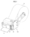
- the printer of this embodiment includes a printer body part 100.
- the printer body part 100 includes a printing part 20 configured to print letters or characters on rolled recording paper 10 and a cutter part 30 configured to cut off a piece of the recording paper 10 subjected to printing.
- a piece (portion) subjected to printing is referred to as "printed piece.”
- the printed piece of the recording paper 10 has a predetermined length. Therefore, in the case of simply performing printing on recording paper and cutting the recording paper to a predetermined length, the configuration illustrated in FIG. 1 may be sufficient.
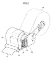
- the printer in order to support the case where there is a need for a presenter function and a retractor function, the printer further includes a presenter unit 40 ( FIG. 2 ).
- the presenter unit 40 is detachably (and reattachably) attached to the printer body part 100 via a bezel 50, which is provided where the recording paper 100 is discharged (ejected).
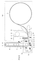
- FIG. 3 is a structural diagram illustrating the printer according to this embodiment, where the presenter unit 40 is connected (attached) to the printer body part 100.
- the printer body part 100 further includes a buffer mechanism part 71 and a control circuit part 72 including a control circuit.
- the rolled recording paper 10 enters the printing part 20 through the buffer mechanism part 71, for example.
- the control circuit part 72 which includes a processor or a central processing unit (CPU), a memory, etc., performs control in the printing part 20, the cutter part 30, the presenter unit 40, and the bezel 50.
- the printing part 20 includes a first motor 21, a platen roller 22, and a thermal head 23.
- the first motor 21 causes the recording paper 10 to be conveyed (fed).
- the rotation of the first motor 21 is transmitted to the platen roller 22, so that the platen roller 22 rotates to convey the recording paper 10.
- the thermal head 23 applies heat to the recording paper 10, which may be thermal paper, in accordance with printing information, so that printing is performed on the conveyed recording paper 10.
- the platen roller 22 rotates so that the recording paper 10 subjected to printing is conveyed from the printing part 20 to pass through the cutter part 30 and thereafter enters the presenter unit 40 through the bezel 50.
- the cutter part 30 includes a movable blade 31 and a stationary blade 32.
- the movable blade 31 is caused to move downward so that the recording paper 10 is cut to a predetermined length with the movable blade 31 and the stationary blade 32.
- the presenter unit 40 includes multiple conveying gears and a conveyor belt attached to two of the conveying gears.
- the conveying gears rotate to move the conveyor belt, so that the recording paper 10 is conveyed by the conveyor belt.
- four conveying gears 41 are provided, and conveyor belts 42 are attached to respective two of the conveying gears 41. That is, two sets of the conveyor belt 42 and the corresponding conveying gears 41 are provided.
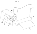
- the presenter unit 40 may further include a rotary drive module part 43 configured to rotate the conveying gears 41 ( FIG. 3 ).
- the rotary drive module part 43 includes a second motor 44.
- the rotation of the second motor 44 is transmitted to a first transmission gear 46 via a rotary part 45 to be further transmitted to a second transmission gear 47 engaged with the first transmission gear 46.
- a (helical) groove corresponding to the first transmission gear 46 is formed on the rotary part 45, so that the groove of the rotary part 45 is engaged with the first transmission gear 46.
- the bezel 50 includes an entrance opening part 51 through which the recording paper 10 enters the bezel 50 from the cutter part 30; a paper discharge opening part 52 through which the retracted recording paper 10 is discharged from the bezel 50; a paper discharge opening part 53 through which the cut recording paper 10 is usually discharged from the bezel 50; a presenter entrance part 54 (a first gap) through which the recording paper 10 enters the presenter unit 40; and a presenter exit part 55 (a second gap) through which the recording paper 10 exits the presenter unit 40.
- the entrance opening part 51 and the paper discharge opening part 53 are substantially aligned with each other or arranged with a positional relationship close to a straight line. This allows the recording paper 10 that enters the bezel 50 from the cutter part 30 through the entrance opening part 51 to be discharged to the paper discharge opening part 53 also in the case where the presenter unit 40 is removed from the bezel 50.
- the presenter entrance part 54 and the presenter exit part 55 are formed by inserting the presenter unit 40 into a predetermined portion of the bezel 50.
- the bezel 50 includes a first sensor S1, a second sensor S2, a third sensor S3, a fourth sensor S4, and a fifth sensor S5.
- the first sensor S1 detects the recording paper 10 that has entered the entrance opening part 51.
- the second sensor S2 detects the recording paper 10 that has entered the presenter entrance part 54.
- the third sensor S3 detects the recording paper 10 in the presenter exit part 55.
- the fourth sensor S4 detects the recording paper 10 that has entered the paper discharge opening part 53.
- the fifth sensor S5 detects the recording paper 10 that has entered the paper discharge opening part 52. According to the printer of this embodiment, it is possible to detect (the presence or absence of) the connection of the presenter unit 40 to the bezel 50 using the second sensor S2 and the third sensor S3.
- the presenter unit 40 includes three sets of the conveyor belt 42 and the corresponding conveying gears 41. As described above, however, the same applies to the case of one, two or four sets of the conveyor belt 42 and the corresponding conveying gears 41.
- the recording paper 10 subjected to printing in the printing part 20 passes through the cutter part 30 to enter the bezel 50 through the entrance opening part 51 and further enter the presenter unit 40 through the presenter entrance part 54.
- the conveying gears 41 rotate so that the recording paper 10 is conveyed by the conveyor belts 42.
- the recording paper 10 is cut with the movable blade 31 and the stationary blade 32 in the cutter part 30.
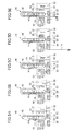
- the cut piece of the recording paper 10 is further conveyed to go toward the paper discharge opening part 53 through the presenter exit part 55, and the conveyance of the recording paper 10 stops at a predetermined position. In this state, the recording paper 10 has been cut. Therefore, the recording paper 10 may be taken out as illustrated in FIG. 5D by being manually pulled out at the paper discharge opening part 53.
- the state illustrated in FIG. 5C is maintained for a predetermined period of time. However, after passage of the predetermined period of time, it is determined that a person supposed to receive the recording paper 10 has forgotten to take the recording paper 10. Therefore, the presenter unit 40 starts a retracting operation to prevent the recording paper 10 on which printing has been performed from being taken away by others.
- This retracting operation is performed by causing the conveying gears 41 to rotate in the reverse direction.
- the recording paper 10 is conveyed on the conveyor belts 42 in the direction reverse to that of the conveying operation in FIGS. 5A through 5C .
- FIG. 5E the recording paper 10 is conveyed in the reverse direction by the conveyor belts 42 to be discharged from the paper discharge opening part 52 through the presenter entrance part 54.
- the curl of the recording paper 10 may be reduced or eliminated by recurling the recording paper 10 by bending the recording paper 10 in the direction opposite to the curling direction of the rolled recording paper 10 in the presenter unit 40. That is, the recording paper 10 is curled in a direction to reduce or eliminate the curl of the roll of the recording paper 10.
- FIGS. 6A through 6C This recurling operation is described with reference to FIGS. 6A through 6C .
- the rolled recording paper 10 has a large curvature radius in an initial (leading) portion. Therefore, the initial portion of the recording paper 10 is discharged with a light curl.
- the rolled recording paper 10 has a small curvature radius in a portion near its end. Therefore, the near-end portion of the recording paper 10 is discharged with a heavy curl (so that the discharged recording paper 10 curls up).
- the thus curled recording paper 10 is not recurled (that is, curled in the opposite direction) even when the recording paper 10 is caused to pass between the thermal head 23 and the platen roller 22 at the time of printing on the recording paper 10 as illustrated in FIG. 6C .
- the recording paper 10 is recurled by being bent in the direction opposite to its curling direction (in which the recording paper 10 is curled) as illustrated in FIGS. 7A and 7B . That is, as illustrated in (a) of FIG. 7A , the recording paper 10 enters the presenter unit 40 according to this embodiment to be bent 90° in the direction opposite to its curling direction via the conveyor belt 42 at a first conveying gear 41a (corresponding to one of the conveying gears 41 illustrated in, for example, FIG. 3 ). In FIG. 7A, (b) illustrates the recurling direction opposite to the curling direction of the recording paper 10 at the conveying gear 41a.
- FIG. 7A illustrates the recurling direction opposite to the curling direction of the recording paper 10 at the conveying gear 41b.
- the recording paper 10 is bent 90° in the direction opposite to its curling direction via the conveyor belt 42 at the conveying gear 41a, and is discharged.
- FIG. 7B (b) illustrates the recurling direction opposite to the curling direction of the recording paper 10 at the conveying gear 41a.
- the recording paper 10 is recurled 360° in total in the direction opposite to the curling direction. As a result, the curling of the recording paper 10 is reduced, so that the recording paper 10 is allowed to be discharged without curling up.
- the rolled recording paper 10 is recurled in the direction opposite to its curling direction.
- the recording paper 10 is recurled along the conveyor belt 42 on its printing surface side. This allows the recording paper 10 to be discharged without curling up.
- the bezel 50 includes a connection part 60 to which the presenter unit 40 is connected.
- the connection part 60 is provided with opening doors (door members) 61 and 62 configured to be closed when the presenter unit 40 is not connected to the connection part 60 and be opened when the presenter unit 40 is connected to the connection part 60.
- the opening doors 61 and 62 may constitute a biparting swing door.
- the opening doors 61 and 62 included in the bezel 50 are closed to prevent dust and the like from entering part of the bezel 50 that the recording paper 10 passes through.
- the opening doors 61 and 62 are pressed by the conveying gear 41a of the presenter unit 40 through the conveyor belt 42 to be open, so that the presenter unit 40 is connected to a predetermined position in the bezel 50.
- the presenter entrance part 54 and the presenter exit part 55 are formed.
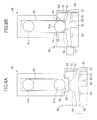
- the opening doors 61 and 62 are again closed by springs (not graphically illustrated) or the like as illustrated in FIG. 8A .
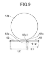
- the opening doors 61 and 62 provided in the bezel 50 have respective end parts 61a and 62a obliquely cut or shaped to overlap each other.
- the end parts 61a and 62a may be obliquely cut so that the opening doors 61 and 62 have respective end faces 61al and 62a1 face each other.
- the end part 61a of the opening door 61 has, for example, an acute angle on the outer side (facing outward) or the side facing toward the presenter unit 40
- the end part 62a of the opening door 62 has, for example, an acute angle on the inner side (facing inward) or the side facing away from the presenter unit 40. Therefore, a length L1 of the opening door 61 (a length measured from the axis of rotation to the end part 61a of the opening door 61) is less (shorter) than a length L2 of the opening door 62 (a length measured from the axis of rotation to the end part 62a of the opening door 62).
- the length L1 is less than the length L2.
- the opening and closing sequence is not limited to the one described above, and may be implemented by offsetting door positions or a differential drive system based on a difference in spring force.
- the conveyor belt 42 is omitted for convenience of graphical representation.
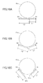
- the conveying gear 41a pushes the opening doors 61 and 62 open. That is, at the time of connecting the presenter unit 40 to the bezel 50, the conveying gear 41a moves as illustrated in order of FIG. 10A to FIG. 10B to FIG. 10C to push the opening doors 61 and 62 open.
- the end part 62a of the opening door 62 is positioned lower (farther from the conveying gear 41a) than the end part 61a of the opening door 61.
- the conveying gear 41a moves as illustrated in order of FIG 10C to FIG. 10B to FIG. 10A so that the opening doors 61 and 62 are closed.
- the end part 62a of the opening door 62 is positioned lower (farther from the conveying gear 41a) than the end part 61a of the opening door 61.
- the conveyor belt 42 is omitted for convenience of graphical representation.
- the opening doors 61 and 62 also have a function as a guide in conveying the recording paper 10 on the conveyor belt 42 by the conveying gear 41a.
- the recording paper 10 that has entered the bezel 50 through the entrance opening part 51 comes into contact with the opening door 62 operating as a guide to move along the surface of the opening door 62.
- the recording paper 10 enters the presenter entrance part 54 to be wrapped around (placed on and along) the conveyor belt 42.
- the recording paper 10a placed along the conveyor belt 42 makes substantially one round on the conveyor belt 42 to move toward the paper discharge opening part 53 along the opening door 61 operating as a guide from the presenter exit part 55.
- the conveying gears 41a and 42b rotate in the reverse direction to feed the recording paper 10 in the opposite direction with the conveyor belt 42.
- the recording paper 10 moves along the opening door 62 to be discharged from the paper discharge opening part 52 provided between the entrance opening part 51 and the paper discharge opening part 53.
- the entrance opening part 51 and the paper discharge opening part 53 are substantially aligned with each other or arranged with a positional relationship close to a straight line in the bezel 50.
- the recording paper 10 that enters the bezel 50 through the entrance opening part 51 is allowed to move substantially straight to be discharged from the paper discharge opening part 53.
- the paper discharge opening part 52 is provided between the entrance opening part 51 and the paper discharge opening part 53 in order to prevent the recording paper 10 that has entered the bezel 50 from the entrance opening part 51 from erroneously entering the paper discharge opening part 52.
- the paper discharge opening part 52 is positioned to be perpendicular to the entrance opening part 51 or to the paper discharge opening part 53.
- connection part 60 is provided opposite the paper discharge opening part 52 between the entrance opening part 51 and the paper discharge opening part 53, and is substantially aligned or arranged with a positional relationship close to a straight line with the paper discharge opening part 52.
- presenter entrance part 54 formed by connecting the presenter unit 40 to the connection part 60 of the bezel 50, is substantially aligned with the paper discharge opening part 52, or is so formed as to allow the recording paper 10 to move toward the paper discharge opening part 52 from the presenter entrance part 54. That is, the presenter entrance part 54 is so formed as to allow the retracted recording paper 10 to smoothly move into the paper discharge opening part 52 from the presenter entrance part 54.
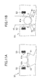
- projection parts 61b and 62b may be provided on parts of the opening doors 61 and 62, respectively, which parts come into contact with the conveying gear 41a of the presenter unit 40 through the conveyor belt 42 as illustrated in FIGS. 11A and 11B .
- the projection parts 61b and 62b may be replaced with pinch roller parts.
- FIG. 11A illustrates the opening doors 61 and 62 in a closed state.
- FIG. 11B illustrates the opening doors 61 and 62 that are opened by the conveying gear 41a through the conveyor belt 42.
- recesses (depressed portions) 61c and 62c may be formed on parts of the opening doors 61 and 62, respectively, which parts come into contact with the conveying gear 41a of the presenter unit 40 through the conveyor belt 42.
- the recesses 61c and 62c are so formed as to correspond in shape to the conveying gear 41a with which the recesses 61c and 62c come into contact through the conveyor belt 42.
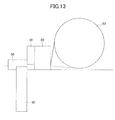
- FIG. 13 is a diagram illustrating another structure of the printer according to this embodiment, where the presenter unit 40 is attached to the bezel 50.
- the printer according to this embodiment may also be structured so that the presenter unit 40 is provided on the side opposite to the recording paper 10 (relative to the paper conveyance path from the printing part 20 to the paper discharge opening part 53 of the bezel 50, for example).
- the rolled recording paper 10 is so rolled as to have its printing surface facing inward as indicated by a broken line, it is possible to recurl the recording paper 10 in the presenter unit 40.
- the printer includes a first driver circuit 111 and a second driver circuit 112.
- the first driver circuit 111 is configured to drive and control the printing part 20 and the cutter part 30.
- the second driver circuit 112 is configured to drive and control the presenter unit 40 and the bezel 50.
- the first driver circuit 111 is connected to a host (host computer) 113 for controlling the printer according to this embodiment, so that the first driver circuit 111 operates based on settings in and instructions from the host 113.
- the first motor 21 and the thermal head 23 of the printing part 20 and the cutter part 30 are connected to and driven and controlled by the first driver circuit 111.
- the second motor 44, the first sensor S1, the second sensor S2, the third sensor S3, the fourth sensor S4, and the fifth sensor S5 are connected to the second driver circuit 112.
- the second driver circuit 112 drives and controls the second motor 44.
- the second driver circuit 112 is connected to the first driver circuit 111, so that information such as settings and instructions in the host 113 is transmitted to the second driver circuit 112 via the first driver circuit 111.
- the printer includes the first driver circuit 111 and the second driver circuit 112.
- the first driver circuit 111 is configured to drive and control the printing part 20 and the cutter part 30.
- the second driver circuit 112 is configured to drive and control the presenter unit 40 and the bezel 50.
- the first driver circuit 111 and the second driver circuit 112 are connected to the control circuit part 72 for controlling the printer according to this embodiment.
- the control circuit part 72 is connected to the host 113. Accordingly, the first driver circuit 111 and the second driver circuit 112 are controlled based on settings in the host 113 and control in the control circuit part 72.
- the first motor 21 and the thermal head 23 of the printing part 20 and the cutter part 30 are connected to and driven and controlled by the first driver circuit 111.
- the second motor 44, the first sensor S1, the second sensor S2, the third sensor S3, the fourth sensor S4, and the fifth sensor S5 are connected to the second driver circuit 112.
- the second driver circuit 112 drives and controls the second motor 44.
- the first sensor S1, the second sensor S2, the third sensor S3, the fourth sensor S4, and the fifth sensor S5 may be optical sensors and be configured to determine the presence or absence of the recording paper 10 or the presenter unit 40 based on the presence or absence of reflected light or the amount of light.
- the first motor 21 and the second motor 44 are stepper motors. Further, the method of controlling a printer according to the second embodiment is carried out based on control executed by the control circuit part 72.
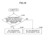
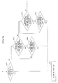
- step S102 it is determined whether the presenter unit 40 is attached to the bezel 50. For example, after the printer is turned on, in step S102, it is determined with the second sensor S2 and the third sensor S3 whether the presenter unit 40 is attached to the bezel 50. For example, if the second sensor S2 and the third sensor S3 detect (light of) a predetermined amount of reflected light, it is determined that the presenter unit 40 is attached to the bezel 50 (YES in step S102), the process proceeds to step S104.
- step S106 the presence or absence of) the attachment of the presenter unit 40 to the bezel 50 may be detected by a light-receiving sensor (not graphically illustrated) in the second sensor S2 receiving light emitted from a light-emitting part (not graphically illustrated) in the third sensor S3 and a light-receiving sensor (not graphically illustrated) in the third sensor S3 receiving light emitted from a light-emitting part (not graphically illustrated) in the second sensor S2.
- a light-receiving sensor not graphically illustrated in the second sensor S2 receiving light emitted from a light-emitting part (not graphically illustrated) in the third sensor S3 and a light-receiving sensor (not graphically illustrated) in the third sensor S3 receiving light emitted from a light-emitting part (not graphically illustrated) in the second sensor S2.
- step S104 a presenter attachment flag is set in the control circuit part 72 or the host 113. That is, it has been determined in step S102 that the presenter unit 40 is attached to the bezel 50 and a presenter attachment flag is set in the control circuit part 72 or the host 113. At this point, the second motor 44 is driven together with the first motor 21 to rotate, being timed to the rotation of the first motor 21.
- step S106 no presenter attachment flag is set in the control circuit part 72 or the host 113. That is, since it has been determined in step S102 that the presenter unit 40 is not attached to the bezel 50, no presenter attachment flag is set in the control circuit part 72 or the host 113.
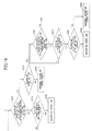
- step S202 of FIG. 17 after the first motor 21 rotates a predetermined number of steps, it is determined whether the recording paper 10 is detected with the first sensor S1. For example, with the recording paper 10 having entered the bezel 50 and the presenter unit 40 as illustrated in FIG. 5A , the recording paper 10 is detected with the first sensor S1. If it is determined that the recording paper 10 is detected with the first sensor S1 (YES in step S202), the process proceeds to step S208. If it is determined that the recording paper 10 is not detected with the first sensor S1 (NO in step S202), the process proceeds to step S204.
- step S204 it is determined whether the first motor 21 has rotated a predetermined maximum number of steps.
- the predetermined maximum number of steps in this case is the number of steps in the first motor 21 for feeding the recording paper 10 until the recording paper 10 is detected by the first sensor S1. If the first motor 21 has rotated the predetermined maximum number of steps, normally, the recording paper 10 is supposed to be detected by the first sensor S1. Therefore, if it is determined that the first motor 21 has rotated a predetermined maximum number of steps (YES in step S204), the process proceeds to step S206. On the other hand, if it is determined that the first motor 21 has not rotated a predetermined maximum number of steps (NO in step S204), the process proceeds to step S202, and the first motor 21 further rotates.
- step S206 it is determined that the recording paper 10 is jammed in the insertion opening.
- the second motor 44 is caused to stop rotating, and a message indicating a paper jam in the insertion opening is displayed in a display part (not graphically illustrated) of the control circuit part 72 or the host 113.
- the recording paper 10 is supposed to have been conveyed by the first motor 21 having rotated a predetermined number of steps, the recording paper 10 is not detected with the first sensor S1. Therefore, the recording paper 10 may be jammed in the entrance opening part S1 of the bezel 50. Therefore, a message to this effect is displayed, and in the case where the first motor 21 and the presenter unit 40 are mounted, the second motor 44 is caused to stop rotating.
- step S208 it is determined whether the recording paper 10 is detected with the second sensor S2. For example, with the recording paper 10 having entered the bezel 50 and the presenter unit 40 as illustrated in FIG. 5A , the recording paper 10 is detected with the second sensor S2. Therefore, if it is determined that the recording paper 10 is detected with the second sensor S2 (YES in step S208), the process proceeds to step S232 of FIG. 18 as indicated by A. On the other hand, if it is determined that the recording paper 10 is not detected with the second sensor S2 (NO in step S208), the process proceeds to step S210.
- step S210 it is determined whether the recording paper 10 is detected with the fourth sensor S4. For example, if the recording paper 10 has entered the paper discharge opening part 52 without entering the presenter unit 40, the recording paper 10 is detected with the fourth sensor S4. Therefore, if it is determined that the recording paper 10 is detected with the fourth sensor S4 (YES in step S210), the process proceeds to step S216. On the other hand, if it is determined that the recording paper 10 is not detected with the fourth sensor S4 (NO in step S210), the process proceeds to step S212.
- step S212 it is determined whether the recording paper 10 is detected with the third sensor S3 or the fifth sensor S5. For example, if the recording paper 10 is detected with the third sensor S3 or the fifth sensor S5 although the recording paper 10 has entered the bezel 50 through the entrance opening part 51, the recording paper 10 may have erroneously entered the paper discharge opening part 52 or the presenter exit part 55. Accordingly, if it is determined that the recording paper 10 is detected with the third sensor S3 or the fifth sensor S5 (YES in step S212), the process proceeds to step S222. On the other hand, if it is determined that the recording paper 10 is not detected with the third sensor S3 or the fifth sensor S5 (NO in step S212), the process proceeds to step S214.
- step S214 it is determined that a paper jam has occurred, and the first motor 21 is caused to stop rotating and a message indicating the occurrence of a paper jam is displayed in the display part (not graphically illustrated) of the host 113 or the control circuit part 72.
- the recording paper 10 is detected with the first sensor S1
- the recording paper 10 is not detected with the second sensor S2, the third sensor S3, the fourth sensor S4, or the fifth sensor S5. Therefore, the recording paper 10 may be jammed inside the bezel 50, for example. Accordingly, a message to this effect is displayed, and the first motor 21 is caused to stop rotating.
- step S216 it is determined whether the first motor 21 has rotated more than a predetermined maximum number of steps.
- the predetermined maximum number of steps in this case is the number of steps in the first motor 21 for feeding the recording paper 10 until the recording paper 10 is detected by the fourth sensor S4. If the first motor 21 has rotated the predetermined maximum number of steps, the recording paper 10 is supposed to be detected by the fourth sensor S4. Therefore, if it is determined that the first motor 21 has rotated a predetermined maximum number of steps (NO in step S216), the process proceeds to step S220. If it is determined that the first motor 21 has rotated more than a predetermined maximum number of steps (YES in step S216), the process proceeds to step S218.
- step S218 it is determined that a paper jam has occurred, and the first motor 21 is caused to stop rotating and a message indicating the occurrence of a paper jam is displayed in the display part (not graphically illustrated) of the host 113 or the control circuit part 72.
- the first motor 21 has rotated more than required. Therefore, the recording paper 10 may be jammed inside the bezel 50, for example. Accordingly, a message to this effect is displayed, and the first motor 21 is caused to stop rotating.
- step S220 it is determined whether a presenter attachment flag is set. If it is determined that a presenter attachment flag is set (YES in step S220), the process proceeds to step S222. If it is determined that no presenter attachment flag is set (NO in step S220), the process proceeds to step S224.
- the presenter attachment flag is set based on the amounts of reflected light detected by the second sensor S2 and the third sensor S3 in step S102.
- step S222 it is determined that the recording paper 10 has not followed a predetermined path, and the first motor 21 and the second motor 44 are caused to stop rotating and a message indicating a paper path abnormality is displayed in the display part (not graphically illustrated) of the host 113 or the control circuit part 72. If the presenter unit 40 is attached to the bezel 50, the recording paper 10 is detected with the second sensor S2. However, the recording paper 10 is detected with the fourth sensor S4 without being detected with the second sensor S2. Therefore, the recording paper 10 may have entered a path different from a predetermined path. Accordingly, a message to this effect is displayed, and the first motor 21 and the second motor 44 are caused to stop rotating.
- step S224 the recording paper 10 is normally discharged from the paper discharge opening part 53. If the presenter unit 40 is not attached to the bezel 50, it is determined that the recording paper 10 has followed a normal path. Therefore, the recording paper 10 is normally discharged from the paper discharge opening part 53.
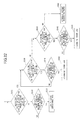
- step S232 it is determined whether the recording paper 10 is detected with the third sensor S3 after a predetermined stepping operation. For example, as illustrated in FIG. 5B and FIG. 5C , if the recording paper 10 has entered the presenter unit 40 and the second motor 44 has rotated a predetermined number of steps, the recording paper 10 is detected with the third sensor S3. Therefore, if it is determined that the recording paper 10 is detected with the third sensor S3 (YES in step S232), the process proceeds to step S238. On the other hand, if it is determined that the recording paper 10 is not detected with the third sensor S3 (NO in step S232), the process proceeds to step S234.
- step S234 it is determined whether the second motor 44 has rotated a predetermined maximum number of steps.
- the predetermined maximum number of steps in this case is the number of steps in the second motor 44 for feeding the recording paper 10 until the recording paper 10 is detected by the third sensor S3. If the second motor 44 has rotated the predetermined maximum number of steps, normally, the recording paper 10 is supposed to be detected by the third sensor S3. Therefore, if it is determined that the second motor 44 has rotated more than or equal to a predetermined maximum number of steps (YES in step S234), the process proceeds to step S236. On the other hand, if it is determined that the second motor 44 has not rotated a predetermined maximum number of steps (NO in step S234), the process proceeds to step S232, and the second motor 44 further rotates.
- step S236 it is determined that a paper jam has occurred, and the first motor 21 and the second motor 44 are caused to stop rotating and a message indicating the occurrence of a paper jam is displayed in the display part (not graphically illustrated) of the host 113 or the control circuit part 72.
- the recording paper 10 is not detected with the third sensor S3 with the second motor 44 having rotated the predetermined maximum number of steps, the recording paper 10 may be jammed inside the presenter unit 40, for example. Therefore, a message to this effect is displayed, and the first motor 21 and the second motor 44 are caused to stop rotating.
- step S2308 it is determined whether the recording paper 10 is cut. For example, as illustrated in FIG. 5C , the recording paper 10 is cut to a predetermined length and discharged. Therefore, if it is determined that the recording paper 10 is cut (YES in step S238), the process proceeds to step S242. On the other hand, if it is determined that the recording paper 10 is not cut (NO in step S238), the process proceeds to step S240.
- step S240 it is determined that there is an abnormality in the length of the recording paper 10, and the first motor 21 and the second motor 44 are caused to stop rotating and a message indicating an abnormality in the length of the recording paper 10 is displayed in the display part (not graphically illustrated) of the host 113 or the control circuit part 72.
- the recording paper 10 has not been cut to a predetermined length in the cutter part 30. Therefore, a message to this effect is displayed, and the first motor 21 and the second motor 44 are caused to stop rotating.
- step S242 it is determined whether the recording paper 10 is detected with the fourth sensor S4. For example, as illustrated in FIG. 5C , with the recording paper 10 having entered the presenter unit 40 and being discharged, the recording paper 10 is detected with the fourth sensor S4. Therefore, if it is determined that the recording paper 10 is detected with the fourth sensor S4 (YES in step S242), the process proceeds to step S262 of FIG. 19 as indicated by B in FIG. 18 . On the other hand, if it is determined that the recording paper 10 is not detected with the fourth sensor S4 (NO in step S242), the process proceeds to step S244.
- step S244 it is determined whether the second motor 44 has rotated a predetermined maximum number of steps.
- the predetermined maximum number of steps in this case is the number of steps in the second motor 44 for feeding the recording paper 10 until the recording paper 10 is detected by the fourth sensor S4. If the second motor 44 has rotated the predetermined maximum number of steps, normally, the recording paper 10 is supposed to be detected by the fourth sensor S4. Therefore, if it is determined that the second motor 44 has rotated more than or equal to a predetermined maximum number of steps (YES in step S244), the process proceeds to step S246. On the other hand, if it is determined that the second motor 44 has not rotated a predetermined maximum number of steps (NO in step S244), the process proceeds to step S242, and the second motor 44 further rotates.
- step S246 it is determined whether the recording paper 10 is detected with the second sensor or the fifth sensor S5. For example, if the recording paper 10 is detected with the second sensor S2 or the fifth sensor S5 although the recording paper 10 has entered the bezel 50, the recording paper 10 may have erroneously entered the paper discharge opening part 52 or the presenter entrance part 54. On the other hand, if the recording paper 10 is not detected with the second sensor S2 or the fifth sensor S5, the recording paper 10 may be jammed. Accordingly, if it is determined that the recording paper 10 is detected with the second sensor S2 or the fifth sensor S5 (YES in step S246), the process proceeds to step S250. On the other hand, if it is determined that the recording paper 10 is not detected with the second sensor S2 or the fifth sensor S5 (NO in step S246), the process proceeds to step S248.
- step S248 it is determined that a paper jam has occurred, and the second motor 44 is caused to stop rotating and a message indicating the occurrence of a paper jam is displayed in the display part (not graphically illustrated) of the host 113 or the control circuit part 72.
- the recording paper 10 is detected with the third sensor S3, the recording paper is not detected with the second sensor S2, the fourth sensor S4, or the fifth sensor S5. Therefore, the recording paper 10 may be jammed inside the bezel 50, for example. Accordingly, a message to this effect is displayed, and the second motor 44 is caused to stop rotating.
- step S250 it is determined that the recording paper 10 has not followed a predetermined path, and the second motor 44 is caused to stop rotating and a message indicating a paper path abnormality is displayed in the display part (not graphically illustrated) of the host 113 or the control circuit part 72.
- the recording paper 10 is detected with the second sensor S2 or the fifth sensor S5 after the recording paper 10 is cut, the recording paper 10 may have entered a path different from a predetermined path. Accordingly, a message to this effect is displayed, and the second motor 44 is caused to stop rotating.
- step S262 it is determined whether the recording paper 10 is detected with the first sensor S1. For example, with the cut recording paper 10 having entered the presenter unit 40 and thereafter being detected with the fourth sensor S4, the recording paper 10 is not detected by the first sensor S1. Therefore, if it is determined that the recording paper 10 is detected with the first sensor S1 (YES in step S262), the process proceeds to step S264. On the other hand, if it is determined that the recording paper 10 is not detected with the first sensor S1 (NO in step S262), the process proceeds to step S266. In the case where the second motor 44 has not rotated a predetermined number of steps, the second motor 44 further rotates.
- step S264 it is determined that a paper jam has occurred, and the second motor 44 is caused to stop rotating and a message indicating the occurrence of a paper jam is displayed in the display part (not graphically illustrated) of the host 113 or the control circuit part 72.
- the recording paper 10 is detected with the first sensor S1 with the second motor 44 having rotated a predetermined number of steps, the recording paper 10 may be jammed inside the bezel 50 or the presenter unit 40, for example. Accordingly, in this case, a message to this effect is displayed, and the second motor 44 is caused to stop rotating.
- step S266 it is determined whether the recording paper 10 is detected with the second sensor S2. For example, as illustrated in FIG. 5C , with the cut recording paper 10 having entered the presenter unit 40 and being discharged, the recording paper 10 is not detected by the second sensor S2. Therefore, if it is determined that the recording paper 10 is detected with the second sensor S2 (YES in step S266), the process proceeds to step S268. On the other hand, if it is determined that the recording paper 10 is not detected with the second sensor S2 (NO in step S266), the process proceeds to step S270.
- step S268 it is determined whether the second motor 44 has rotated a predetermined maximum number of steps after the recording paper 10 is cut.
- the predetermined maximum number of steps in this case is the number of steps in the second motor 44 for feeding the recording paper 10 until the recording paper 10 is no longer detected by the second sensor S2. If the second motor 44 has rotated the predetermined maximum number of steps, normally, the recording paper 10 is supposed to be no longer detected by the second sensor S2. Therefore, if it is determined that the second motor 44 has rotated more than or equal to a predetermined maximum number of steps (YES in step S268), the process proceeds to step S264. On the other hand, if it is determined that the second motor 44 has not rotated a predetermined maximum number of steps (NO in step S268), the process proceeds to step S266, and the second motor 44 further rotates.
- step S270 it is determined whether the recording paper 10 is detected with the third sensor S3. For example, with the cut recording paper 10 being discharged, the recording paper 10 is not detected with the third sensor S3. Therefore, if it is determined that the recording paper 10 is detected with the third sensor S3 (YES in step S270), the process proceeds to step S272. On the other hand, if it is determined that the recording paper 10 is not detected with the third sensor S3 (NO in step S270), the process proceeds to step S282 of FIG. 20 as indicated by C in FIG. 19 .
- step S272 it is determined whether the second motor 44 has rotated a predetermined maximum number of steps after the recording paper 10 is cut.
- the predetermined maximum number of steps in this case is the number of steps in the second motor 44 for feeding the recording paper 10 until the recording paper 10 is no longer detected by the third sensor S3. If the second motor 44 has rotated the predetermined maximum number of steps, normally, the recording paper 10 is supposed to be no longer detected by the third sensor S3. Therefore, if it is determined that the second motor 44 has rotated more than or equal to a predetermined maximum number of steps (YES in step S272), the process proceeds to step S264. On the other hand, if it is determined that the second motor 44 has not rotated a predetermined maximum number of steps (NO in step S272), the process proceeds to step S270, and the second motor 44 further rotates.
- step S282 the cut recording paper 10 is held. That is, part of the cut recording paper 10 has stuck out of the paper discharge opening part 53 with the cut recording paper 10 being held between the conveyor belt 42 and the opening door 61 ( FIG. 8B ). In this state, the recording paper 10 may be manually pulled out.
- step S284 it is determined whether the recording paper is detected with the fourth sensor S4. If the recording paper 10 has been manually pulled out, the recording paper 10 is not detected by the fourth sensor S4. Therefore, if it is determined that the recording paper is detected with the fourth sensor S4 (YES in step S284), the process proceeds to step S288. On the other hand, if it is determined that the recording paper is not detected with the fourth sensor S4 (NO in step S284), the process proceeds to step S286.
- step S286 it is recognized (determined) that the recording paper 10 has been manually pulled out from the paper discharge opening part 53, and the process ends.
- step S288 it is determined whether a predetermined period of time has passed since the start of the state of step S282. For example, if the recording paper 10 has not been pulled out after passage of a predetermined period of time since it is made possible for a person to pull out the recording paper 10, it is believed that the person has no intention to pull out the recording paper 10. Therefore, in this case, the recording paper 10 on which printing has been performed may be retracted in order to protect information recorded on the recording paper 10. Accordingly, if it is determined that a predetermined period of time has passed (YES in step S288), the process proceeds to step S290. On the other hand, if it is determined that a predetermined period of time has not passed (NO in step S288), the process proceeds to step S284.
- step S290 it is determined whether a retraction flag for retracting the recording paper 10 is set.
- the retraction flag for retracting the recording paper 10 is preset by the host 113 at the stage of initialization. If the retraction flag for retracting the recording paper 10 is set (YES in step S290), the process proceeds to step S302 of FIG. 21 as indicated by D in FIG. 20 . On the other hand, if the retraction flag for retracting the recording paper 10 is not set (NO in step S290), the process proceeds to step S292.
- step S292 it is determined that an error has occurred in pulling out the recording paper 10, and a message indicating the occurrence of an error in pulling out the recording paper 10 is displayed in the display part (not graphically illustrated) of the host 113 or the control circuit part 72.
- the recording paper 10 remains untaken (not pulled out by a person) and is not retracted. Therefore, a message to this effect is displayed.
- step S302 the second motor 44 is caused to rotate in the reverse direction, so that the recording paper 10 is conveyed in the direction opposite to the direction in which the recording paper 10 has been conveyed in the presenter unit 40.
- the second motor 44 is caused to rotate in the reverse direction in order to retract the recording paper 10.
- step S304 it is determined whether the recording paper 10 is detected with the third sensor S3. For example, when the cut recording paper 10 is conveyed in the opposite direction, first, the recording paper 10 is detected with the third sensor S3. Therefore, if it is determined that the recording paper 10 is detected with the third sensor S3 (YES in step S304), the process proceeds to step S310. On the other hand, if it is determined that the recording paper 10 is not detected with the third sensor S3 (NO in step S304), the process proceeds to step S306.
- step S306 it is determined whether the second motor 44 has rotated a predetermined maximum number of steps after the second motor 44 is caused to rotate in the reverse direction.
- the predetermined maximum number of steps in this case is the number of steps in the second motor 44 for feeding the recording paper 10, with the recording paper 10 not being detected with the third sensor S3, until the recording paper 10 is detected by the third sensor S3 by the reverse rotation of the second motor 44. If the second motor 44 has rotated the predetermined maximum number of steps in the reverse direction, normally, the recording paper 10 is supposed to be detected by the third sensor S3. Therefore, if it is determined that the second motor 44 has rotated more than or equal to a predetermined maximum number of steps (YES in step S306), the process proceeds to step S308. On the other hand, if it is determined that the second motor 44 has not rotated a predetermined maximum number of steps (NO in step S306), the process proceeds to step S304, and the second motor 44 further rotates in the reverse direction.
- step S308 it is determined that an error has occurred in retracting the recording paper 10, and the second motor 44 is caused to stop rotating and a message indicating the occurrence of an error in retracting the recording paper 10 is displayed in the display part (not graphically illustrated) of the host 113 or the control circuit part 72. That is, if the recording paper 10 is not detected with the third sensor S3 with the second motor 44 having rotated the predetermined maximum number of steps in the reverse direction, the recording paper 10 may not be retracted. Therefore, a message to this effect is displayed, and the second motor is caused to stop rotating.
- step S310 it is determined whether the recording paper 10 is detected with the third sensor S3. For example, if the second motor 44 is caused to rotate in the reverse direction so that the recording paper 10 is detected by the third sensor S3, and then the second motor 44 further rotates in the reverse direction, the recording paper 10 is no longer detected by the third sensor S3. Accordingly, if it is determined that the recording paper 10 is detected with the third sensor S3 (YES in step S310), the process proceeds to step S312. On the other hand, if it is determined that the recording paper 10 is not detected with the third sensor S3 (NO in step S310), the process proceeds to step S316.
- step S312 it is determined whether the second motor 44 has rotated a predetermined maximum number of steps in the reverse direction after the second motor 44 is caused to rotate in the reverse direction.
- the predetermined maximum number of steps in this case is the number of steps in the second motor 44 for feeding the recording paper 10 until the recording paper 10 is no longer detected by the third sensor S3 by the reverse rotation of the second motor 44. If the second motor 44 has rotated the predetermined maximum number of steps in the reverse direction, normally, the recording paper 10 is supposed to be no longer detected by the third sensor S3. Accordingly, if it is determined that the second motor 44 has rotated more than or equal to a predetermined maximum number of steps in the reverse direction (YES in step S312), the process proceeds to step S314. On the other hand, if it is determined that the second motor 44 has not rotated a predetermined maximum number of steps in the reverse direction (NO in step S312), the process proceeds to step S310, and the second motor 44 further rotates in the reverse direction.
- step S314 it is determined that a paper jam has occurred, and the second motor 44 is caused to stop rotating and a message indicating the occurrence of a paper jam is displayed in the display part (not graphically illustrated) of the host 113 or the control circuit part 72. That is, if the recording paper 10 is detected with the third sensor S3 with the second motor 44 having rotated the predetermined maximum number of steps in the reverse direction, the recording paper 10 may be jammed inside the bezel 50 or the presenter unit 40, for example. Accordingly, in this case, a message to this effect is displayed, and the second motor 44 is caused to stop rotating.
- step S316 it is determined whether the recording paper 10 is detected with the second sensor S2. For example, if the cut recording paper 10 is conveyed in the opposite direction from a state with the recording paper 10 not being detected with the second sensor S2, the recording paper 10 is detected by the second sensor S2. Therefore, if it is determined that the recording paper 10 is detected with the second sensor S2 (YES in step S316), the process proceeds to step S332 of FIG. 22 as indicated by E in FIG. 21 . On the other hand, if it is determined that the recording paper 10 is not detected with the second sensor S2 (NO in step S316), the process proceeds to step S318.
- step S3108 it is determined whether the second motor 44 has rotated a predetermined maximum number of steps in the reverse direction after the second motor 44 is caused to rotate in the reverse direction.
- the predetermined maximum number of steps in this case is the number of steps in the second motor 44 for feeding the recording paper 10 until the recording paper 10 is detected by the second sensor S2 by the reverse rotation of the second motor 44 with the recording paper 10 not being detected with the second sensor S2. If the second motor 44 has rotated the predetermined maximum number of steps in the reverse direction, normally, the recording paper 10 is supposed to be detected by the second sensor S2. Accordingly, if it is determined that the second motor 44 has rotated more than or equal to a predetermined maximum number of steps in the reverse direction (YES in step S318), the process proceeds to step S320. On the other hand, if it is determined that the second motor 44 has not rotated a predetermined maximum number of steps in the reverse direction (NO in step S318), the process proceeds to step S316, and the second motor 44 further rotates in the reverse direction.
- step S320 it is determined that a paper jam has occurred, and the second motor 44 is caused to stop rotating and a message indicating the occurrence of a paper jam is displayed in the display part (not graphically illustrated) of the host 113 or the control circuit part 72. That is, if the recording paper 10 is not detected with the second sensor S2 with the second motor 44 having rotated the predetermined maximum number of steps in the reverse direction, the recording paper 10 may be jammed inside the presenter unit 40, for example. Accordingly, in this case, a message to this effect is displayed, and the second motor 44 is caused to stop rotating.
- step S332 it is determined whether the recording paper 10 is detected with the fifth sensor S5. For example, if the cut recording paper 10 is conveyed in the opposite direction from a state with the recording paper 10 not being detected with the fifth sensor S5, the recording paper 10 is detected by the fifth sensor S5. Therefore, if it is determined that the recording paper 10 is detected with the fifth sensor S5 (YES in step S332), the process proceeds to step S338. On the other hand, if it is determined that the recording paper 10 is not detected with the fifth sensor S5 (NO in step S332), the process proceeds to step S334.
- step S334 it is determined whether the second motor 44 has rotated a predetermined maximum number of steps in the reverse direction after the second motor 44 is caused to rotate in the reverse direction.
- the predetermined maximum number of steps in this case is the number of steps in the second motor 44 for feeding the recording paper 10, with the recording paper 10 not being detected with the fifth sensor S5, until the recording paper 10 is detected by the fifth sensor S5 by the reverse rotation of the second motor 44. If the second motor 44 has rotated the predetermined maximum number of steps in the reverse direction, normally, the recording paper 10 is supposed to be detected by the fifth sensor S5.
- step S334 if it is determined that the second motor 44 has rotated more than or equal to a predetermined maximum number of steps in the reverse direction (YES in step S334), the process proceeds to step S336. On the other hand, if it is determined that the second motor 44 has not rotated a predetermined maximum number of steps in the reverse direction (NO in step S334), the process proceeds to step S332, and the second motor 44 further rotates in the reverse direction.
- step S3366 it is determined that a paper jam has occurred, and the second motor 44 is caused to stop rotating and a message indicating the occurrence of a paper jam is displayed in the display part (not graphically illustrated) of the host 113 or the control circuit part 72. That is, if the recording paper 10 is not detected with the fifth sensor S5 with the second motor 44 having rotated the predetermined maximum number of steps in the reverse direction, the recording paper 10 may be jammed inside the presenter unit 40, for example. Accordingly, in this case, a message to this effect is displayed, and the second motor 44 is caused to stop rotating.
- step S3308 it is determined whether the recording paper 10 is detected with the second sensor S2. For example, the recording paper 10 is no longer detected by the second sensor S2 by causing the second motor 44 to rotate in the reverse direction. Therefore, if it is determined that the recording paper 10 is detected with the second sensor S2 (YES in step S338), the process proceeds to step S340. On the other hand, if it is determined that the recording paper 10 is not detected with the second sensor S2 (NO in step S338), the process proceeds to step S344.
- step S340 it is determined whether the second motor 44 has rotated a predetermined maximum number of steps in the reverse direction after the second motor 44 is caused to rotate in the reverse direction.
- the predetermined maximum number of steps in this case is the number of steps in the second motor 44 for feeding the recording paper 10 until the recording paper 10 is no longer detected by the second sensor S2 by the reverse rotation of the second motor 44. If the second motor 44 has rotated the predetermined maximum number of steps in the reverse direction, normally, the recording paper 10 is supposed to be no longer detected by the second sensor S2. Accordingly, if it is determined that the second motor 44 has rotated more than or equal to a predetermined maximum number of steps in the reverse direction (YES in step S340), the process proceeds to step S342. On the other hand, if it is determined that the second motor 44 has not rotated a predetermined maximum number of steps in the reverse direction (NO in step S340), the process proceeds to step S338, and the second motor 44 further rotates in the reverse direction.
- step S342 it is determined that a paper jam has occurred, and the second motor 44 is caused to stop rotating and a message indicating the occurrence of a paper jam is displayed in the display part (not graphically illustrated) of the host 113 or the control circuit part 72. That is, if the recording paper 10 is detected with the second sensor S2 with the second motor 44 having rotated the predetermined maximum number of steps in the reverse direction, the recording paper 10 may be jammed inside the bezel 50 or the presenter unit 40, for example. Accordingly, in this case, a message to this effect is displayed, and the second motor 44 is caused to stop rotating.
- step S344 it is determined whether the recording paper 10 is detected with the fifth sensor S5. For example, the recording paper 10 is no longer detected by the fifth sensor S5 by causing the second motor 44 to rotate in the reverse direction. Therefore, if it is determined that the recording paper 10 is detected with the fifth sensor S5 (YES in step S344), the process proceeds to step S346. On the other hand, if it is determined that the recording paper 10 is not detected with the fifth sensor S5 (NO in step S344), the process proceeds to step S350.
- step S346 it is determined whether the second motor 44 has rotated a predetermined maximum number of steps in the reverse direction after the second motor 44 is caused to rotate in the reverse direction.
- the predetermined maximum number of steps in this case is the number of steps in the second motor 44 for feeding the recording paper 10 until the recording paper 10 is no longer detected by the fifth sensor S5 by the reverse rotation of the second motor 44. If the second motor 44 has rotated the predetermined maximum number of steps in the reverse direction, normally, the recording paper 10 is supposed to be no longer detected by the fifth sensor S5. Accordingly, if it is determined that the second motor 44 has rotated more than or equal to a predetermined maximum number of steps in the reverse direction (YES in step S346), the process proceeds to step S348. On the other hand, if it is determined that the second motor 44 has not rotated a predetermined maximum number of steps in the reverse direction (NO in step S346), the process proceeds to step S344, and the second motor 44 further rotates in the reverse direction.
- step S348 it is determined that a paper jam has occurred, and the second motor 44 is caused to stop rotating and a message indicating the occurrence of a paper jam is displayed in the display part (not graphically illustrated) of the host 113 or the control circuit part 72. That is, if the recording paper 10 is detected with the fifth sensor S5 with the second motor 44 having rotated the predetermined maximum number of steps in the reverse direction, the recording paper 10 may be jammed inside the bezel 50 or the presenter unit 40, for example. Accordingly, in this case, a message to this effect is displayed, and the second motor 44 is caused to stop rotating.
- step S350 it is recognized (determined) that the recording paper 10 has been normally retracted through the paper discharge opening part 52, and the process ends.
Landscapes
- Physics & Mathematics (AREA)
- General Physics & Mathematics (AREA)
- Handling Of Sheets (AREA)
Applications Claiming Priority (2)
| Application Number | Priority Date | Filing Date | Title |
|---|---|---|---|
| JP2011124515A JP5792518B2 (ja) | 2011-06-02 | 2011-06-02 | プリンタ装置 |
| JP2011226263A JP5806580B2 (ja) | 2011-10-13 | 2011-10-13 | プリンタ装置及びプリンタ装置の制御方法 |
Publications (2)
| Publication Number | Publication Date |
|---|---|
| EP2529938A2 true EP2529938A2 (de) | 2012-12-05 |
| EP2529938A3 EP2529938A3 (de) | 2016-08-17 |
Family
ID=46651329
Family Applications (1)
| Application Number | Title | Priority Date | Filing Date |
|---|---|---|---|
| EP12169771.8A Withdrawn EP2529938A3 (de) | 2011-06-02 | 2012-05-29 | Drucker und Steuerungsverfahren dafür |
Country Status (4)
| Country | Link |
|---|---|
| US (1) | US8827581B2 (de) |
| EP (1) | EP2529938A3 (de) |
| KR (1) | KR101368918B1 (de) |
| CN (1) | CN102837504B (de) |
Cited By (5)
| Publication number | Priority date | Publication date | Assignee | Title |
|---|---|---|---|---|
| ITMO20130019A1 (it) * | 2013-01-28 | 2014-07-29 | Custom Engineering S P A | Stampante per chioschi |
| WO2017100325A1 (en) * | 2015-12-07 | 2017-06-15 | Avery Dennison Retail Information Services, | Cutter accessory for printing system |
| BE1025507B1 (nl) * | 2016-12-15 | 2019-03-28 | Zebra Technologies Corporation | Beweegbare mediageleider voor media-verwerkingsapparaten |
| US10494131B2 (en) | 2017-05-01 | 2019-12-03 | Avery Dennison Retail Information Services, Llc | Combination printer and cutting apparatus |
| US11071415B2 (en) | 2018-01-15 | 2021-07-27 | Charles Agnew Osborne, Jr. | Dispenser for rolled sheet materials with belt drive system |
Families Citing this family (5)
| Publication number | Priority date | Publication date | Assignee | Title |
|---|---|---|---|---|
| JP6498977B2 (ja) * | 2015-03-20 | 2019-04-10 | 富士通コンポーネント株式会社 | プリンタ |
| US9855775B1 (en) | 2016-12-12 | 2018-01-02 | Xerox Corporation | Apparatus and method for protecting printheads from irregular media in a printer |
| KR102147194B1 (ko) * | 2018-08-08 | 2020-08-25 | 대한민국 | 급지장치 |
| CN114055958B (zh) | 2018-11-06 | 2023-02-28 | 大数据奥尼尔公司 | 打印机设备和用于操作包括打印头的打印机设备的方法 |
| CN110989943B (zh) * | 2019-03-22 | 2020-12-29 | 河南工业贸易职业学院 | 基于云计算的参数解析装置 |
Citations (2)
| Publication number | Priority date | Publication date | Assignee | Title |
|---|---|---|---|---|
| JP2003019845A (ja) | 2001-07-09 | 2003-01-21 | Nagano Fujitsu Component Kk | プリンタ装置 |
| JP2007130842A (ja) | 2005-11-09 | 2007-05-31 | Fujitsu Component Ltd | プリンタ装置 |
Family Cites Families (28)
| Publication number | Priority date | Publication date | Assignee | Title |
|---|---|---|---|---|
| US5779379A (en) * | 1997-03-28 | 1998-07-14 | Interbold | Receipt form handling system for automated banking machine |
| BR9800333A (pt) * | 1997-01-21 | 1999-06-29 | Xerox Corp | Módulo removível de desencrespador de folha fendida postal e empilhador de alta capacidade módulo externo removível que está adaptado para assentar numa bandeja receptora de folha de uma máquina de impressão para desencrespar e captar folhas cortadas e máquina de impressão |
| US6196741B1 (en) * | 1997-05-28 | 2001-03-06 | Matsushita Electric Industrial Co., Ltd. | Printer |
| US5954438A (en) * | 1997-10-30 | 1999-09-21 | Bdt Products, Inc. | Sheet presenter and method of using same |
| JP2000229760A (ja) * | 1999-02-09 | 2000-08-22 | Fuji Xerox Co Ltd | 画像形成システム、カール補正装置 |
| US6547464B1 (en) * | 1999-12-01 | 2003-04-15 | Diebòld, Incorporated | Automated transaction machine printer |
| JP3748357B2 (ja) * | 2000-03-17 | 2006-02-22 | セイコーインスツル株式会社 | 用紙排出装置 |
| JP4621335B2 (ja) * | 2000-06-28 | 2011-01-26 | セイコーエプソン株式会社 | 情報端末用プリンタユニット |
| JP2003256880A (ja) * | 2002-03-05 | 2003-09-12 | Sii P & S Inc | 用紙排出装置 |
| US6634296B2 (en) * | 2002-03-20 | 2003-10-21 | International Business Machines Corporation | Printer document presenter apparatus and method |
| US7048457B2 (en) * | 2003-02-24 | 2006-05-23 | International Business Machines Corporation | Document delivery system apparatus and method |
| US20040175221A1 (en) * | 2003-03-05 | 2004-09-09 | Toshiba Tec Kabushiki Kaisha | Printer |
| US7275483B2 (en) * | 2003-03-20 | 2007-10-02 | Transact Technologies Incorporated | Jam resistant printer bezel |
| CN1286657C (zh) * | 2003-04-15 | 2006-11-29 | 精工爱普生株式会社 | 打印机 |
| US7192208B2 (en) * | 2003-09-02 | 2007-03-20 | Futurelogic, Inc. | Rewritable card printer |
| US20060072953A1 (en) * | 2004-10-04 | 2006-04-06 | Daniel Vienneau | Ticket presenter for use with a ticket printer having a tear bar therein |
| KR100739940B1 (ko) | 2006-01-04 | 2007-07-16 | 윤영철 | 영수증 발행기 및 그 제어방법 |
| KR100797516B1 (ko) | 2006-04-07 | 2008-01-24 | 윤영철 | 발권기를 위한 티켓 프리젠터 |
| KR100738117B1 (ko) * | 2006-07-06 | 2007-07-12 | 삼성전자주식회사 | 압전 방식의 잉크젯 프린트헤드 |
| JP2008068950A (ja) * | 2006-09-12 | 2008-03-27 | Nippon Primex Inc | 用紙排出ガイド |
| JP2009083448A (ja) * | 2007-10-03 | 2009-04-23 | Seiko Instruments Inc | プリンタおよび発行装置 |
| JP2009091064A (ja) | 2007-10-04 | 2009-04-30 | Seiko Instruments Inc | プリンタおよび発行装置 |
| JP2009196239A (ja) * | 2008-02-22 | 2009-09-03 | Seiko Instruments Inc | 給紙装置 |
| JP5394678B2 (ja) | 2008-08-25 | 2014-01-22 | セイコーインスツル株式会社 | サーマルプリンタ |
| JP4964978B2 (ja) * | 2009-09-08 | 2012-07-04 | 東芝テック株式会社 | 媒体検出方法、媒体検出装置、媒体排出装置、及び印刷装置 |
| JP5532836B2 (ja) * | 2009-11-11 | 2014-06-25 | セイコーエプソン株式会社 | 記録装置、記録装置の制御方法、及び、プログラム |
| JP5685009B2 (ja) * | 2010-06-23 | 2015-03-18 | 日本プリメックス株式会社 | Led発光機能付ベゼル |
| JP6077271B2 (ja) * | 2012-10-31 | 2017-02-08 | 富士通コンポーネント株式会社 | プリンタ装置 |
-
2012
- 2012-03-09 KR KR1020120024662A patent/KR101368918B1/ko not_active Expired - Fee Related
- 2012-05-22 US US13/477,695 patent/US8827581B2/en not_active Expired - Fee Related
- 2012-05-29 EP EP12169771.8A patent/EP2529938A3/de not_active Withdrawn
- 2012-06-01 CN CN201210307585.2A patent/CN102837504B/zh not_active Expired - Fee Related
Patent Citations (2)
| Publication number | Priority date | Publication date | Assignee | Title |
|---|---|---|---|---|
| JP2003019845A (ja) | 2001-07-09 | 2003-01-21 | Nagano Fujitsu Component Kk | プリンタ装置 |
| JP2007130842A (ja) | 2005-11-09 | 2007-05-31 | Fujitsu Component Ltd | プリンタ装置 |
Cited By (17)
| Publication number | Priority date | Publication date | Assignee | Title |
|---|---|---|---|---|
| RU2633260C2 (ru) * | 2013-01-28 | 2017-10-11 | Кастом С.П.А. | Печатающее устройство для киосков |
| WO2014115000A1 (en) * | 2013-01-28 | 2014-07-31 | Custom S.P.A. | Printer for kiosks |
| ITMO20130019A1 (it) * | 2013-01-28 | 2014-07-29 | Custom Engineering S P A | Stampante per chioschi |
| US9688083B2 (en) | 2013-01-28 | 2017-06-27 | Custom S.P.A. | Printer for kiosks |
| EP3524397A1 (de) * | 2015-12-07 | 2019-08-14 | Avery Dennison Retail Information Services, LLC | Schneiderzubehör für drucksystem |
| CN108472822A (zh) * | 2015-12-07 | 2018-08-31 | 艾利丹尼森零售信息服务公司 | 用于打印系统的切割机附件 |
| US10179465B2 (en) | 2015-12-07 | 2019-01-15 | Avery Dennison Retail Information Services, Llc | Cutter accessory for printing system |
| WO2017100325A1 (en) * | 2015-12-07 | 2017-06-15 | Avery Dennison Retail Information Services, | Cutter accessory for printing system |
| BE1025507B1 (nl) * | 2016-12-15 | 2019-03-28 | Zebra Technologies Corporation | Beweegbare mediageleider voor media-verwerkingsapparaten |
| US10494131B2 (en) | 2017-05-01 | 2019-12-03 | Avery Dennison Retail Information Services, Llc | Combination printer and cutting apparatus |
| US11045966B2 (en) | 2017-05-01 | 2021-06-29 | Avery Dennison Retail Information Services, Llc | Stand-alone cutting apparatus |
| US11052559B2 (en) | 2017-05-01 | 2021-07-06 | Avery Dennison Retail Information Servives, LLC | Combination printer and cutting apparatus |
| US11148846B2 (en) | 2017-05-01 | 2021-10-19 | Avery Dennison Retail Information Services, Llc | Method for reducing label waste using a cutting apparatus |
| US12036688B2 (en) | 2017-05-01 | 2024-07-16 | Avery Dennison Retail Information Services Llc | Stand-alone cutting apparatus |
| US11071415B2 (en) | 2018-01-15 | 2021-07-27 | Charles Agnew Osborne, Jr. | Dispenser for rolled sheet materials with belt drive system |
| US11730324B2 (en) | 2018-01-15 | 2023-08-22 | Valve Solutions, Inc. | Dispenser for rolled sheet materials with belt drive system |
| US12114813B2 (en) | 2018-01-15 | 2024-10-15 | Valve Solutions, Inc. | Dispenser for rolled sheet materials with belt drive system |
Also Published As
| Publication number | Publication date |
|---|---|
| CN102837504B (zh) | 2015-04-01 |
| US8827581B2 (en) | 2014-09-09 |
| KR20120135021A (ko) | 2012-12-12 |
| EP2529938A3 (de) | 2016-08-17 |
| CN102837504A (zh) | 2012-12-26 |
| US20120308288A1 (en) | 2012-12-06 |
| KR101368918B1 (ko) | 2014-03-25 |
Similar Documents
| Publication | Publication Date | Title |
|---|---|---|
| EP2529938A2 (de) | Drucker und Steuerungsverfahren dafür | |
| JP5298166B2 (ja) | 用紙排出装置、用紙排出方法、画像形成装置および画像形成方法 | |
| EP2727736B1 (de) | Drucker mit Präsentationsteil und Schneidvorrichtung mit gemeinsamer Bewegung | |
| EP2927006B1 (de) | Drucker | |
| EP2813368B1 (de) | Druckervorrichtung und verfahren zum steuern einer druckervorrichtung | |
| US20040175221A1 (en) | Printer | |
| JP2001105383A (ja) | シート切断装置 | |
| JP5792518B2 (ja) | プリンタ装置 | |
| JP2009018923A (ja) | 用紙搬送装置および画像形成装置 | |
| JP5806580B2 (ja) | プリンタ装置及びプリンタ装置の制御方法 | |
| JP3770002B2 (ja) | プリンタ及びその制御方法 | |
| CN106457853B (zh) | 打印机装置 | |
| JP2001162584A (ja) | シート切断装置 | |
| JP4838156B2 (ja) | 媒体搬送機構 | |
| JP4846009B2 (ja) | 用紙排出装置及び用紙排出装置を備える画像形成装置 | |
| US9193187B2 (en) | Gap control method for a media processing device, and a media processing device | |
| EP3257678A1 (de) | Quittungsdrucker | |
| JP4849391B2 (ja) | 印刷装置、及び自動券売機 | |
| EP3257679B1 (de) | Quittungsdrucker | |
| CN116198237A (zh) | 卷筒纸打印机 | |
| JP2006008266A (ja) | 折り畳み装置及び印刷システム | |
| JP6704759B2 (ja) | 用紙脱落防止補助ユニット | |
| JP6107517B2 (ja) | 搬送装置及びこれを有する記録装置 | |
| JP2007118360A (ja) | プリンタ | |
| JP2010218161A (ja) | 印刷装置 |
Legal Events
| Date | Code | Title | Description |
|---|---|---|---|
| PUAI | Public reference made under article 153(3) epc to a published international application that has entered the european phase |
Free format text: ORIGINAL CODE: 0009012 |
|
| AK | Designated contracting states |
Kind code of ref document: A2 Designated state(s): AL AT BE BG CH CY CZ DE DK EE ES FI FR GB GR HR HU IE IS IT LI LT LU LV MC MK MT NL NO PL PT RO RS SE SI SK SM TR |
|
| AX | Request for extension of the european patent |
Extension state: BA ME |
|
| RIC1 | Information provided on ipc code assigned before grant |
Ipc: G07F 17/42 20060101ALI20160318BHEP Ipc: B41J 13/10 20060101AFI20160318BHEP Ipc: B41J 15/04 20060101ALI20160318BHEP |
|
| PUAL | Search report despatched |
Free format text: ORIGINAL CODE: 0009013 |
|
| AK | Designated contracting states |
Kind code of ref document: A3 Designated state(s): AL AT BE BG CH CY CZ DE DK EE ES FI FR GB GR HR HU IE IS IT LI LT LU LV MC MK MT NL NO PL PT RO RS SE SI SK SM TR |
|
| AX | Request for extension of the european patent |
Extension state: BA ME |
|
| RIC1 | Information provided on ipc code assigned before grant |
Ipc: B65H 35/00 20060101ALI20160712BHEP Ipc: B41J 11/70 20060101ALI20160712BHEP Ipc: B41J 2/32 20060101ALI20160712BHEP Ipc: B41J 15/04 20060101ALI20160712BHEP Ipc: B41J 13/10 20060101AFI20160712BHEP Ipc: G07F 17/42 20060101ALI20160712BHEP |
|
| 17P | Request for examination filed |
Effective date: 20161125 |
|
| RBV | Designated contracting states (corrected) |
Designated state(s): AL AT BE BG CH CY CZ DE DK EE ES FI FR GB GR HR HU IE IS IT LI LT LU LV MC MK MT NL NO PL PT RO RS SE SI SK SM TR |
|
| STAA | Information on the status of an ep patent application or granted ep patent |
Free format text: STATUS: THE APPLICATION HAS BEEN WITHDRAWN |
|
| 18W | Application withdrawn |
Effective date: 20171031 |