EP2530252A2 - Joint d'étanchéité souple - Google Patents
Joint d'étanchéité souple Download PDFInfo
- Publication number
- EP2530252A2 EP2530252A2 EP12170184A EP12170184A EP2530252A2 EP 2530252 A2 EP2530252 A2 EP 2530252A2 EP 12170184 A EP12170184 A EP 12170184A EP 12170184 A EP12170184 A EP 12170184A EP 2530252 A2 EP2530252 A2 EP 2530252A2
- Authority
- EP
- European Patent Office
- Prior art keywords
- formed flexible
- section
- flexible seal
- vessel
- coupled
- Prior art date
- Legal status (The legal status is an assumption and is not a legal conclusion. Google has not performed a legal analysis and makes no representation as to the accuracy of the status listed.)
- Withdrawn
Links
- 230000007704 transition Effects 0.000 description 10
- 230000001052 transient effect Effects 0.000 description 3
- 238000002485 combustion reaction Methods 0.000 description 2
- 238000003754 machining Methods 0.000 description 2
- 239000002184 metal Substances 0.000 description 2
- 238000000034 method Methods 0.000 description 2
- 230000008569 process Effects 0.000 description 2
- 230000004075 alteration Effects 0.000 description 1
- 238000001816 cooling Methods 0.000 description 1
- 230000008878 coupling Effects 0.000 description 1
- 238000010168 coupling process Methods 0.000 description 1
- 238000005859 coupling reaction Methods 0.000 description 1
- 230000007423 decrease Effects 0.000 description 1
- 230000003247 decreasing effect Effects 0.000 description 1
- 239000004744 fabric Substances 0.000 description 1
- 239000012530 fluid Substances 0.000 description 1
- 230000035515 penetration Effects 0.000 description 1
- 230000004044 response Effects 0.000 description 1
- 238000007789 sealing Methods 0.000 description 1
- 238000006467 substitution reaction Methods 0.000 description 1
- 230000037303 wrinkles Effects 0.000 description 1
Images

Classifications
-
- F—MECHANICAL ENGINEERING; LIGHTING; HEATING; WEAPONS; BLASTING
- F16—ENGINEERING ELEMENTS AND UNITS; GENERAL MEASURES FOR PRODUCING AND MAINTAINING EFFECTIVE FUNCTIONING OF MACHINES OR INSTALLATIONS; THERMAL INSULATION IN GENERAL
- F16J—PISTONS; CYLINDERS; SEALINGS
- F16J3/00—Diaphragms; Bellows; Bellows pistons
- F16J3/04—Bellows
- F16J3/047—Metallic bellows
-
- F—MECHANICAL ENGINEERING; LIGHTING; HEATING; WEAPONS; BLASTING
- F01—MACHINES OR ENGINES IN GENERAL; ENGINE PLANTS IN GENERAL; STEAM ENGINES
- F01D—NON-POSITIVE DISPLACEMENT MACHINES OR ENGINES, e.g. STEAM TURBINES
- F01D11/00—Preventing or minimising internal leakage of working-fluid, e.g. between stages
- F01D11/005—Sealing means between non relatively rotating elements
-
- F—MECHANICAL ENGINEERING; LIGHTING; HEATING; WEAPONS; BLASTING
- F16—ENGINEERING ELEMENTS AND UNITS; GENERAL MEASURES FOR PRODUCING AND MAINTAINING EFFECTIVE FUNCTIONING OF MACHINES OR INSTALLATIONS; THERMAL INSULATION IN GENERAL
- F16J—PISTONS; CYLINDERS; SEALINGS
- F16J15/00—Sealings
- F16J15/02—Sealings between relatively-stationary surfaces
- F16J15/06—Sealings between relatively-stationary surfaces with solid packing compressed between sealing surfaces
- F16J15/08—Sealings between relatively-stationary surfaces with solid packing compressed between sealing surfaces with exclusively metal packing
- F16J15/0887—Sealings between relatively-stationary surfaces with solid packing compressed between sealing surfaces with exclusively metal packing the sealing effect being obtained by elastic deformation of the packing
-
- F—MECHANICAL ENGINEERING; LIGHTING; HEATING; WEAPONS; BLASTING
- F05—INDEXING SCHEMES RELATING TO ENGINES OR PUMPS IN VARIOUS SUBCLASSES OF CLASSES F01-F04
- F05D—INDEXING SCHEME FOR ASPECTS RELATING TO NON-POSITIVE-DISPLACEMENT MACHINES OR ENGINES, GAS-TURBINES OR JET-PROPULSION PLANTS
- F05D2250/00—Geometry
- F05D2250/70—Shape
Definitions
- the subject matter disclosed herein relates to a formed flexible seal.
- combustion occurs in a combustor and the high temperature and high energy fluids produced by that combustion are directed to flow from the combustor into a transition piece and toward a turbine section.
- the transition piece and the turbine section are normally coupled to one another at the aft frame of the transition piece and the stage 1 nozzle. This coupling can be achieved by advanced cloth seals.
- the transition piece and the stage 1 nozzle may experience differential axial and radial deformation that affects several components including the seals between the transition piece and the stage 1 nozzle.
- field experience has revealed that the stage 1 nozzle tends to creep and due to nozzle creep deflection, seal effectiveness decreases. This decreased seal effectiveness in turn results in cooling air leakage to the primary flow path causing performance loss.
- a formed flexible seal includes a first section coupled to a first vessel, a second section coupled to a second vessel and a formed flexible section connected at opposite end portions thereof to the first and second sections and having a central portion extending between the opposite end portions to absorb differential thermal growth of the first and second vessels to which the first and second sections are coupled.
- the central portion may comprise a formed flexible portion to absorb at least one of radial, circumferential and axial differential thermal growth of the first and second vessels.
- a formed flexible seal provides cost effective and rugged design to improve sealing effectiveness in at least the transient environment.
- the formed flexible seal shows prompt thermal response and, due to temperature changes, the formed flexible seal flexes to provide ample room for deformation with fixed or substantially fixed transition piece and stage 1 nozzle end constraints.
- the formed flexible seal can be assembled with the transition piece and stage 1 nozzle using screw/bolt fasteners to ensure metal to metal contact or other similar arrangements.
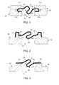
- the seal 10 includes a first section 20, which is coupled to a first vessel 30 of, for example, a gas turbine engine, a second section 40, which is coupled to a second vessel 50 of the exemplary gas turbine engine, which is disposed downstream from the first vessel 30, and a formed flexible section 60.
- the first vessel 30 may include a transition piece of the exemplary gas turbine engine and the second vessel 50 may include a stage 1 nozzle.
- the first section 20 is coupled to an aft frame of the transition piece and the second section 40 is coupled to a side wall of the stage 1 nozzle.
- the seal 10 can be applied to any components of the gas turbine engine or another similar apparatus.
- the formed flexible section 60 has opposite end portions 61 and 62 and is connected at the opposite end portions 61 and 62 to the first and second sections 20 and 40, respectively.
- the formed flexible section 60 further includes a central, formed flexible portion 70 extending between the opposite end portions 61 and 62.
- the formed flexible portion 70 flexes to responsively absorb torsion forces applied to the first and second sections 20 and 40 by the first and second vessels 30 and 50 in accordance with at least one or more of radial, circumferential and axial differential thermal growth of the first and second vessels 30 and 50.
- first and second vessels 30 and 50 may translate relative to the other.
- This relative translation causes one or both of the first and second vessels 30 and 50 to pull on the first and second sections 20 and 40.
- This pulling is absorbed by the formed flexible section 60 whereby the formed flexible portion 70 flexes and flattens.
- an effective overall length of the seal 10 is increased such that the relative translation can be absorbed.
- the first section 20 may be coupled to the first vessel 30 by an end 21 thereof being bent into a preloaded U-shape 210 and inserted into a preloaded groove 31 of the first vessel 30.
- This preloaded groove 31 may include a shoulder portion 310 and a flap 311, which radially opposes the shoulder portion 310, and can be formed by machining or another similar process.
- the second section 40 may be coupled to the second vessel 50 by an end 41 thereof being bent into a preloaded U-shape 410 and inserted into a preloaded groove 51 of the second vessel 50.
- This preloaded groove 51 may include a shoulder portion 510 and a flap 511, which radially opposes the shoulder portion 510, and can be formed by machining or another similar process.
- the configuration of FIG. 1 can serve to prevent seal crushing in event of transition piece aft frame and stage 1 nozzle penetration during transient cycles.
- the first section 20 may be coupled to the first vessel 30 by being preloaded and circumferentially mated with a flange 32 of the first vessel 30.
- the second section 40 may be coupled to the second vessel 50 by being preloaded and circumferentially mated with a flange 52 of the second vessel 50.
- the first section 20 may be coupled to the first vessel 30 by being at least one of welded and screwed or otherwise attached to the first vessel 30 at a weld point 33 or attachment point.
- the second section 40 may be coupled to the second vessel 50 by being at least one of welded and screwed or otherwise attached to the second vessel 50 at a weld point 53 or attachment point.
- the first and second sections 20 and 40 have substantially similar lengths and, at least at an initial time prior to any at least one of radial, axial and circumferential differential thermal growth of the first and second vessels 30 and 50, the first and second sections 20 and 40 are oriented substantially in parallel with one another. In some cases, the first and second sections 20 and 40 may be coplanar and/or coaxial.
- the formed flexible portion 70 protrudes radially inwardly and outwardly from respective planes of the first and second sections 20 and 40. In accordance with alternative embodiments, the formed flexible portion 70 may also protrude radially inwardly from the respective planes of the first and second sections 20 and 40.
- the formed flexible portion 70 may also protrude radially outwardly from the respective planes of the first and second sections 20 and 40.
- the formed flexible portion 70 has a height as measured from respective planes of the first and second sections 20 and 40 that is substantially larger than a thickness of the first section 20, the second section 40 or the formed flexible section 60.
- the formed flexible portion 70 may be provided in a double c-shape 710.
- the first section 20 curves radially inwardly along a curved section 711 towards an oppositely curved hairpin section 712.
- the second section 40 curves radially outwardly along a curved section 713 towards an oppositely curved hairpin section 714.
- the hairpin sections 712 and 714 are connected by a central section 715.
- the formed flexible portion 70 may be symmetric about the central section 715 and reversely configured as described herein.
- the formed flexible portion 70 may be provided in a corrugated z-shape 720.
- the first section 20 extends radially inwardly and the second section 40 remains radially constrained.
- Both the first section 20 and the second section 40 are connected to a central z-shaped section 721 and the first section 20, the second section 40 and the central z-shaped section 721 are corrugated such that each is drawn or bent into folds, alternating furrows and ridges, or wrinkles.
- the corrugations may be smooth or angular.
- the formed flexible portion 70 may be reversely configured as described herein.
- the formed flexible portion 70 may be provided as a bellow portion 730.
- the bellow portion 730 has a shape that is similar to that of the corrugated z-shape except that the bellow portion has a central bellow section 731 that has multiple folds 732 and may or may not include corrugations.
Landscapes
- Engineering & Computer Science (AREA)
- General Engineering & Computer Science (AREA)
- Mechanical Engineering (AREA)
- Gasket Seals (AREA)
Applications Claiming Priority (1)
| Application Number | Priority Date | Filing Date | Title |
|---|---|---|---|
| US13/152,619 US20120306168A1 (en) | 2011-06-03 | 2011-06-03 | Formed flexible seal |
Publications (1)
| Publication Number | Publication Date |
|---|---|
| EP2530252A2 true EP2530252A2 (fr) | 2012-12-05 |
Family
ID=46172730
Family Applications (1)
| Application Number | Title | Priority Date | Filing Date |
|---|---|---|---|
| EP12170184A Withdrawn EP2530252A2 (fr) | 2011-06-03 | 2012-05-31 | Joint d'étanchéité souple |
Country Status (3)
| Country | Link |
|---|---|
| US (1) | US20120306168A1 (fr) |
| EP (1) | EP2530252A2 (fr) |
| CN (1) | CN102808698A (fr) |
Families Citing this family (6)
| Publication number | Priority date | Publication date | Assignee | Title |
|---|---|---|---|---|
| US8544852B2 (en) | 2011-06-03 | 2013-10-01 | General Electric Company | Torsion seal |
| US10422239B2 (en) | 2015-03-18 | 2019-09-24 | Siemens Energy, Inc. | Seal assembly in a gas turbine engine |
| CN112460630A (zh) * | 2020-10-27 | 2021-03-09 | 中国船舶重工集团公司第七0三研究所 | 一种燃气轮机高温区间隙平面间密封组件 |
| US11629616B1 (en) * | 2022-02-17 | 2023-04-18 | Power Systems Mfg., Llc | Radially flexible flange joint for exhaust manifold |
| CN115306490A (zh) * | 2022-07-29 | 2022-11-08 | 中国联合重型燃气轮机技术有限公司 | 用于透平叶片的密封片和透平叶片间的密封结构 |
| CN115370427B (zh) * | 2022-08-09 | 2026-03-31 | 中国联合重型燃气轮机技术有限公司 | 透平密封组件、透平和燃气轮机 |
-
2011
- 2011-06-03 US US13/152,619 patent/US20120306168A1/en not_active Abandoned
-
2012
- 2012-05-31 EP EP12170184A patent/EP2530252A2/fr not_active Withdrawn
- 2012-06-04 CN CN2012101803376A patent/CN102808698A/zh active Pending
Non-Patent Citations (1)
| Title |
|---|
| None |
Also Published As
| Publication number | Publication date |
|---|---|
| CN102808698A (zh) | 2012-12-05 |
| US20120306168A1 (en) | 2012-12-06 |
Similar Documents
| Publication | Publication Date | Title |
|---|---|---|
| EP2530252A2 (fr) | Joint d'étanchéité souple | |
| US8225614B2 (en) | Shim for sealing transition pieces | |
| EP2559859A1 (fr) | Fixation d'extrémité de joint | |
| JP4322600B2 (ja) | シール装置 | |
| EP2530251A2 (fr) | Joint d'articulation | |
| JP6240307B2 (ja) | 板金タービンハウジング | |
| US9512734B2 (en) | Sealing of the flow channel of a turbomachine | |
| JP2013526674A (ja) | 排ガスターボチャージャのタービンハウジング | |
| US9670791B2 (en) | Flexible finger seal for sealing a gap between turbine engine components | |
| CN111902607B (zh) | 用于涡轮发动机的涡轮的冷却设备 | |
| US20120104747A1 (en) | Compliant sealing joint | |
| JP2012017847A (ja) | 流体機械 | |
| EP3249168B1 (fr) | Système de retenue et d'étanchéité | |
| CN102589008A (zh) | 涡轮机燃料喷嘴组件 | |
| US10690060B2 (en) | Triple bend finger seal and deflection thereof | |
| US11125095B2 (en) | Sliding seal | |
| US8544852B2 (en) | Torsion seal | |
| CN116906127A (zh) | 一种涡轮导向器的固定结构、航空发动机 |
Legal Events
| Date | Code | Title | Description |
|---|---|---|---|
| PUAI | Public reference made under article 153(3) epc to a published international application that has entered the european phase |
Free format text: ORIGINAL CODE: 0009012 |
|
| AK | Designated contracting states |
Kind code of ref document: A2 Designated state(s): AL AT BE BG CH CY CZ DE DK EE ES FI FR GB GR HR HU IE IS IT LI LT LU LV MC MK MT NL NO PL PT RO RS SE SI SK SM TR |
|
| AX | Request for extension of the european patent |
Extension state: BA ME |
|
| STAA | Information on the status of an ep patent application or granted ep patent |
Free format text: STATUS: THE APPLICATION IS DEEMED TO BE WITHDRAWN |
|
| 18D | Application deemed to be withdrawn |
Effective date: 20141202 |