EP2530255A2 - Séparateur d'eau et procédé de séparation d'eau à partir d'un écoulement de vapeur humide - Google Patents
Séparateur d'eau et procédé de séparation d'eau à partir d'un écoulement de vapeur humide Download PDFInfo
- Publication number
- EP2530255A2 EP2530255A2 EP20120152589 EP12152589A EP2530255A2 EP 2530255 A2 EP2530255 A2 EP 2530255A2 EP 20120152589 EP20120152589 EP 20120152589 EP 12152589 A EP12152589 A EP 12152589A EP 2530255 A2 EP2530255 A2 EP 2530255A2
- Authority
- EP
- European Patent Office
- Prior art keywords
- water
- sieve
- steam
- turbine
- screen
- Prior art date
- Legal status (The legal status is an assumption and is not a legal conclusion. Google has not performed a legal analysis and makes no representation as to the accuracy of the status listed.)
- Withdrawn
Links
Images

Classifications
-
- F—MECHANICAL ENGINEERING; LIGHTING; HEATING; WEAPONS; BLASTING
- F01—MACHINES OR ENGINES IN GENERAL; ENGINE PLANTS IN GENERAL; STEAM ENGINES
- F01D—NON-POSITIVE DISPLACEMENT MACHINES OR ENGINES, e.g. STEAM TURBINES
- F01D25/00—Component parts, details, or accessories, not provided for in, or of interest apart from, other groups
- F01D25/32—Collecting of condensation water; Drainage ; Removing solid particles
-
- F—MECHANICAL ENGINEERING; LIGHTING; HEATING; WEAPONS; BLASTING
- F01—MACHINES OR ENGINES IN GENERAL; ENGINE PLANTS IN GENERAL; STEAM ENGINES
- F01K—STEAM ENGINE PLANTS; STEAM ACCUMULATORS; ENGINE PLANTS NOT OTHERWISE PROVIDED FOR; ENGINES USING SPECIAL WORKING FLUIDS OR CYCLES
- F01K7/00—Steam engine plants characterised by the use of specific types of engine; Plants or engines characterised by their use of special steam systems, cycles or processes; Control means specially adapted for such systems, cycles or processes; Use of withdrawn or exhaust steam for feed-water heating
- F01K7/16—Steam engine plants characterised by the use of specific types of engine; Plants or engines characterised by their use of special steam systems, cycles or processes; Control means specially adapted for such systems, cycles or processes; Use of withdrawn or exhaust steam for feed-water heating the engines being only of turbine type
- F01K7/22—Steam engine plants characterised by the use of specific types of engine; Plants or engines characterised by their use of special steam systems, cycles or processes; Control means specially adapted for such systems, cycles or processes; Use of withdrawn or exhaust steam for feed-water heating the engines being only of turbine type the turbines having inter-stage steam heating
- F01K7/223—Inter-stage moisture separation
-
- F—MECHANICAL ENGINEERING; LIGHTING; HEATING; WEAPONS; BLASTING
- F05—INDEXING SCHEMES RELATING TO ENGINES OR PUMPS IN VARIOUS SUBCLASSES OF CLASSES F01-F04
- F05D—INDEXING SCHEME FOR ASPECTS RELATING TO NON-POSITIVE-DISPLACEMENT MACHINES OR ENGINES, GAS-TURBINES OR JET-PROPULSION PLANTS
- F05D2220/00—Application
- F05D2220/70—Application in combination with
- F05D2220/72—Application in combination with a steam turbine
-
- F—MECHANICAL ENGINEERING; LIGHTING; HEATING; WEAPONS; BLASTING
- F05—INDEXING SCHEMES RELATING TO ENGINES OR PUMPS IN VARIOUS SUBCLASSES OF CLASSES F01-F04
- F05D—INDEXING SCHEME FOR ASPECTS RELATING TO NON-POSITIVE-DISPLACEMENT MACHINES OR ENGINES, GAS-TURBINES OR JET-PROPULSION PLANTS
- F05D2260/00—Function
- F05D2260/20—Heat transfer, e.g. cooling
- F05D2260/202—Heat transfer, e.g. cooling by film cooling
Definitions
- the present invention relates to a water separator and a method for separating water from a wet steam flow, for example a wet steam flow occurring in the region of a steam turbine plant. Furthermore, the invention relates to the use of such a water separator in a steam turbine.
- the use of a water separator in a water-steam cycle of a steam turbine plant is for example from the EP 0 848 208 B1 known.
- the water separator is used for separating water (including impurities dissolved therein) from a wet steam flow between an evaporator and a superheater of the water-steam cycle.
- the known water separator is formed as a "separator bottle" of cylindrical shape provided with two tangential steam inlets at a shallow angle to the horizontal to create a downward swirling flow of the incoming wet steam in the separator bottle.
- the separator thus operates on the principle of a "centrifugal separator".
- screen is used here in a very broad or figurative sense. As will be explained below, the screen is not used in a conventional manner, but has one or (as is common in conventional screens) multiple openings (screen openings).
- a "screen surface” consists of one or more screen openings and the area adjacent the screen opening or the areas between the plurality of screen openings.
- the water separator has only a "first sieve opening” (of the first sieve) and only a “second sieve opening” (of the second sieve).
- first sieve and / or the second sieve can each be provided with a plurality of first and second sieve openings.
- the sieve arrangement provided in the water separator according to the invention can comprise more than two sieves.
- the function of the vapor sieve assembly according to the invention which consists of at least two sieves with mutually offset sieve openings, is based on the fact that the vapor is subjected to a flow deflection after flowing through the first vapor opening of the first (upstream) sieve in order to the transversely arranged second sieve opening of the second (downstream) sieve to arrive.
- Decisive here is that in this curved course of the vapor flow between the two sieves, the water droplets contained in the steam due to their inertia tend to flow through a less curved flow path and thus in a region of the second sieve adjacent to (or at a distance to) the second sieve opening (or in a region between second screen openings) impinge.
- these areas eg, massive screen surfaces
- a water separator can be designed so that the directions of the steam inlet (at the first screen openings) and the steam outlet (eg at the second screen openings) are identical, wherein advantageously a very short length of the water separator is possible. In the simplest case, this length is defined by the sum of the "screen thicknesses" of the first and second screens plus the "screen spacing" between the two screens. If the sieve arrangement also has a third sieve (and possibly also a fourth sieve, etc.), the overall length of the water separator increases accordingly.
- a further advantage of the water separator or active principle according to the invention is the "scalability" of the construction to a predetermined cross-sectional area of the relevant wet steam flow. Since each sieve used can have one or more sieve openings and the arrangement of several sieve openings on each sieve can be largely arbitrary, the construction according to the invention can be adapted in a simple manner to any cross-sectional areas and cross-sectional shapes of the relevant wet steam flow.
- the water discharge device comprises at least one water drainage channel extending in the interior of the second wire and at least one opening in this water drainage channel at a baffle surface of the second wire adjacent to the second wire opening.
- the water discharge device further comprises means for actively discharging water located in the water drainage channel (eg by using a "suction" by means of a water pump).
- the first sieve can be used, for example, as a sieve plate, e.g. B. flat screen plate, be formed. At the first sieve, no components of the water discharge device are required, so that the first sieve can advantageously be provided with a very small thickness. In a particularly simple design it is a metal plate (eg of steel), which is provided with a first sieve opening or with a plurality of first sieve openings. A plurality of first screen openings is preferably provided in a regular arrangement on a one-dimensional or two-dimensional grid (in a mathematical sense).
- the second sieve (and possibly further sieves) can also be designed as a sieve plate (eg made of metal, with one or more second sieve openings).
- a sieve plate eg made of metal, with one or more second sieve openings.
- at least one water drainage channel can be formed inside this filter plate.
- said water drainage channel in the second sieve can constitute a water collection channel which is used for merging and jointly discharging water which passes into the water drainage channel via several branches, whereby these branches are supplied via corresponding junctions at the areas between the second screen openings with water fractions (separated from the wet steam flow).
- the water separator further comprises a third sieve downstream of the second sieve and having at least one third sieve opening offset from the second sieve opening, the water discharge device further discharging water adjacent the third sieve opening to the third Sieve impinges, is formed.
- the water separator can also comprise more than three sieves arranged one behind the other.
- the second, third, etc. sieve each with suitable water drainage channels in the interior of this z. B. as a flat screen plates shaped sieves be provided, through which the impacted water can be removed.
- a drain construction In the very first, ie the furthest upstream screen such a drain construction is unnecessary. Rather, it is essential that the second sieve in the direction of flow and, if appropriate, further sieves following in the steam sieve arrangement are each equipped with a suitable drain construction and each sieve opening of a "subsequent sieve" is arranged with an offset to the or each of the sieve openings of the "preceding sieve” is.
- a separation of water from a wet steam flow is provided, which occurs within a turbine housing of a steam turbine.
- a steam turbine of the type of interest here may include a turbine housing having a turbine shaft rotatably mounted therein about a turbine axis, along the turbine shaft having a plurality of steam-flow stage groups each formed of a shaft-fixed blade structure and a stationary stator vane structure cooperating therewith in that a pressure and temperature-reducing expansion of the water vapor takes place in each of the step groups through which water vapor flows successively.
- Such steam turbines are known from the prior art and can be used for example in nuclear power, geothermal, solar thermal, biomass or other power plants advantageous for the production of electrical energy.
- This known steam turbine comprises a turbine housing with a turbine shaft ("turbine runner”) rotatably mounted therein around a turbine axis, wherein a plurality of steam-flow stage groups are provided along the turbine shaft each formed of a shaft-fixed blade structure and a housing-fixed vane structure meshing therewith.
- turbine operation a pressure and temperature-reducing expansion of the water vapor takes place in the successively flowed through by steam vapor stage groups to use energy from the water vapor for rotary drive of the turbine shaft.
- an embodiment of the steam turbine in which at least one of the stage groups for discharging wet steam is designed with a water content of more than 5%, wherein in the steam flow path behind this stage group a water separator of the type already described above is arranged, via which the water vapor after reduction of the water content to less than 3%, in particular less than 2%, is delivered to a subsequent of the step groups.
- At least one of the stage groups is designed to dispense wet steam having a water content of more than 5%, preferably in the range of 5 to 15%.
- the relevant stage group thus advantageously allows a high efficiency of energy conversion.
- a water separator is arranged in the steam flow path behind this step group, via which the water vapor is discharged to a subsequent one of the step groups after reduction of the water content to less than 3%, preferably less than 2%, or even about 0% ,
- the steam turbine according to the invention can be used in particular for generating electrical energy by means of an electric generator driven therefrom.
- live steam with a pressure of z. B. more than 100 bar and a temperature of z. B. more than 400 ° C are supplied.
- the expanded steam can reach a pressure of, for. B. less than 1 bar (ie vacuum) and a temperature of z. B. less than 50 ° C.
- no intermediate superheating in the steam flow path is provided in order to avoid the associated plant-related expenditure.
- the steam turbine may comprise two, three, four or more stages groups, wherein in the steam flow path behind a or at least one water separator having the above-described function can be arranged in each case, or several stages groups.
- the water separator is housed completely within the turbine housing.
- the (at least one) water separator in this case has a "steam sieve arrangement" of the type already described above for trapping water droplets.
- the vapor sieve assembly preferably housed within the turbine housing, may be radially sealed from the turbine housing and / or from the turbine shaft to avoid a flow of wet steam past the vapor sifter assembly during turbine operation.
- the water separator is partially disposed outside of the turbine housing.
- all parts of the water separator located outside of the turbine housing are preferably structurally combined with the turbine housing, ie, for example. B. housed in flanged, welded or integrally molded as housing casings with the housing body piping or formed from such piping.
- All parts of the Wassersepartors are preferably housed within a (imaginary) cylindrical space whose axial length corresponds to the axial extent of the turbine shaft within the turbine housing and whose radial diameter is smaller than 4 times, preferably smaller than 3 times, the maximum diameter a turbine housing body (turbine housing without Wassersepartorkomponenten).
- the Dampfsieban ever can be installed outside of the turbine housing and connected to at least one steam supply line and at least one vapor return line to the interior of the turbine housing.
- the steam sieve assembly comprises a plurality of sieves (one behind the other) with the sieve opening (s) of each sieve being offset from the sieve opening (s) of a sieve immediately upstream in the steam sieve assembly.
- water separated from the wet steam leads out of the turbine and is supplied to another point in a water-steam cycle.
- this cycle in the known manner, in the steam flow path at the end of the turbine led out exhaust steam z. B. first to a condenser and from there on to a steamer to be supplied by the steamer heater with high pressure and high temperature provided live steam, especially at the beginning of the steam flow curve of the turbine (at a "live steam").
- a plurality of water separators of the said function are provided, each of which is arranged between two steam groups in the steam flow course of the successive stages groups.
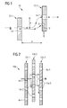
- Fig. 1 illustrates a water separator 10 for separating water from a wet steam flow, such as may occur in the region of a water-steam cycle of a steam turbine plant.
- wet steam denotes in the usual way a mixture of water vapor (in the gaseous phase) and water (in the liquid phase).
- the flow through the water separator 10 takes place in Fig. 1 from left to right (flow direction).
- Flow paths of the vapor are symbolized by arrows, the dashed arrows symbolizing the flow paths of the water vapor portion and the solid arrows symbolizing the flow paths of the water portion (condensate in the form of water droplets).
- the water separator 10 comprises a first sieve 12-1 with a first sieve opening 14-1 and a second sieve 12-2 arranged downstream therefrom in the flow direction at a distance d and having a second sieve opening 14-2 which is offset at an offset a to the first sieve opening 14-2. 1 is arranged. As it is in the left part of Fig. 1 is shown at the first screen opening 14-1 first wet steam containing a "dry" vapor content and a water content (condensate) enters the screen assembly of the water separator 10 a.
- the water droplets forming the water fraction can not or do not follow the acceleration or deflection of the steam flow in the intermediate space between the sieves 12-1 and 12-2 to the extent in which the dry vapor portion is deflected.
- the velocity vectors of steam and water droplets differ in magnitude and direction.
- junction 16 adjacent the screen opening 14-2 forms, together with the water drainage channel 18, a water drainage device for discharging water adjacent to the screen opening 14-2 on the second screen 12-2, thus effectively "missing" the opening 14-2.
- Fig. 1 symbolizes the length of the drawn arrows the amount of velocity vectors. It can be seen that the water droplets (solid arrows) flow rather straight and at a rather constant speed through the sieve opening 14-1 and continue to impinge on the baffle or the junction 16 of the subsequent screen 12-2, whereas the speed of the vapor fraction in the Each of the screen openings 14-1 and 14-2 accelerates and slows down slightly behind each of these screen openings.
- the equipment of the baffle of the second screen 12-2 with the described drain construction 16, 18 avoids entrainment of the water impacted on the baffle through the second screen opening 14-2.
- the screen openings are respectively elongated, namely orthogonal to the flow direction and orthogonal to the "deflection direction" (The deflection direction is z Fig. 1 Vertical).
- This design of the screen openings is z. B. in particular for in Fig. 1 in which case the first sieve 12-1 and the second sieve 12-2 each have only a single sieve opening 14-1 or 14-2 exhibit.
- such an elongate shape can also be provided for the case of several screen openings of the first and / or second screen.
- Fig. 2 is a schematic sectional view of a Dampfsieban note a water separator 10a, which is formed in the illustrated example of three successive screen plates 12a-1, 12a-2 and 12a-3.
- each of the screen plates 12a-1 to 12a-3 is provided with a regular arrangement of a plurality of screen openings 14a-1, 14a-2 and 14a-3.
- the screen openings 14a-1, 14a-2 or 14a-3 are respectively elongated orthogonal to the flow direction and orthogonal to the "deflection direction", in particular when the screen openings 14a-1, 14a-2 or 14a are arranged. 3 on a respective one-dimensional (mathematical) grid.
- Deviating from the sieve openings 14a-1, 14a-2 and 14a-3, however, z. B. also have an at least approximately circular shape, in particular when the screen openings 14a-1, 14a-2 or 14a-3 are arranged on a respective two-dimensional (mathematical) grid.
- FIG. 2 the water drain construction of the second screen plate 12a-2 (and the third screen plate 12a-3) is not shown.
- a device for removing water which impinges in areas between the second screen openings 14a-2 (or in areas between the screen openings 14a-3 of the third screen plate 12a-3), could for example be formed as already described with reference to FIG Fig. 1 has been described.
- Corresponding drainage structures are in the example according to Fig. 2 to provide both in the second screen plate 12a-2 and in the drilled screen plate 12a-3.
- the channels can be on the output side z. B. in a common water collection channel, which in turn is connected to the input of a water pump to "suck off” the trapped water “active” or deduce.
- Fig. 3 shows a steam turbine 30b comprising an approximately cylindrical turbine housing 32b with a turbine shaft 36b rotatably mounted therein about a turbine axis 34b.
- Each of the stage groups 38b-1 to 38b-4 is formed of a blade structure rotationally connected to the turbine shaft 36b and a vane structure cooperating therewith and held stationary to the turbine housing 32b.
- a blade structure herein consists of a series of axially spaced blade rows with blades 40b projecting radially from the turbine shaft 36b
- a stator structure consists of a series of axially spaced apart blade rows with a plurality of stator blades 42b radially inwardly projecting from stationary ones Steam flow course of a stage group alternately blades and vanes are flowed around by water vapor.
- each of the succession of steam-flow stage groups 38b-1 to 38b-4 takes place in each case a pressure and temperature-reducing expansion of the water vapor.
- stage groups 38b-1, 38b-2 and 38b-3 are designed for the delivery of wet steam with a water content of, for example, about 5 to 15% (and accordingly a water vapor content of about 85 to 95%) , wherein in the respective further steam flow course behind these stage groups 38b-1, 38b-2, 38b-3 is in each case a water separator 10b-1, 10b-2 or 10b-3 is arranged, by means of which the wet steam at these locations each (liquid) water is withdrawn.
- the steam is thus delivered with a reduced proportion of water (and correspondingly increased water vapor content) to the respective subsequent (38b-2, 38b-3 and 38b-4) of the stage groups 38b-1 to 38b-4 in the steam flow course.
- the steam turbine 30b is designed and operated such that the water content of the wet steam upstream of each of the water separators 10b-1, 10b-2, and 10b-3, respectively, of about 10% after passing through this downstream water separator is substantially reduced smaller value is reduced.
- the proportion of water is practically reduced to 0%, thus generating "dry steam".
- Each of the water separators 10b-1 to 10b-3 dries the water vapor more or less strongly, so that downstream of it especially the energetically high-quality water vapor for further expansion in the turbine 30b is continued.
- the water withdrawn from the water separators 10b-1 to 10b-3 may, for example, be taken out of the turbine 30b and recycled (not shown), such as to reuse it in the water-steam cycle of a respective power plant.
- the illustrated construction of the turbine 30b makes it possible to dispense with expensive external devices for so-called reheating, as are used in the prior art to avoid excessively high proportions of water, in particular in low-pressure turbine areas. If intermediate reheating is nevertheless provided in the illustrated turbine 30b, then the devices used therefor can advantageously be made less expensive.
- stage groups 38b-1 to 38b-4 and the water separators 10b-1 to 10b-3 are to be understood as exemplary only and can be modified.
- water separators may also be arranged only behind some or those groups of steps in which a release of wet steam is to be expected. This is usually the case in conventional turbine designs only in so-called medium-pressure stages and especially low-pressure stages, or in so-called "saturated steam processes".
- steam turbine 30b accordingly also represent only such a medium-pressure level or low-pressure stage (a total larger steam turbine plant).
- the water separators 10b-1 to 10b-3 are housed completely within the turbine housing 32b in the illustrated example. In this case, if necessary, water discharge lines are led out through the turbine housing 32b (not shown).
- Each of the water separators 10b-1 to 10b-3 includes a steam strainer arrangement for trapping water droplets from the steam flow, for example as described above with respect to FIG Fig. 1 and 2 already described.
- the steam turbine 30b advantageously implements an "internal vapor separation" by means of which impermissibly high vaporization during expansion, and consequently blade erosion and similar problems, can be avoided, in particular when using lower live steam pressures and temperatures. Any protective measures on the turbine components, such. As hardening of the blades or heating of the vanes, are unnecessary or can be provided with less effort.
- water separators may differ from the embodiment according to Fig. 3 Also, a partial arrangement of components of these water separators are selected outside of an actual turbine housing.
- a water separator can be connected to the turbine housing via a relatively short pipe arrangement (principle: pipe removal).
- a water separator may be coupled to the turbine housing via a conduit connection formed by a housing casting (eg, "bleed port").
Landscapes
- Engineering & Computer Science (AREA)
- Mechanical Engineering (AREA)
- General Engineering & Computer Science (AREA)
- Chemical & Material Sciences (AREA)
- Combustion & Propulsion (AREA)
- Separating Particles In Gases By Inertia (AREA)
Applications Claiming Priority (1)
| Application Number | Priority Date | Filing Date | Title |
|---|---|---|---|
| DE102011006066.9A DE102011006066B4 (de) | 2011-03-24 | 2011-03-24 | Wasserseparator und Verfahren zum Abtrennen von Wasser aus einer Nassdampfströmung |
Publications (1)
| Publication Number | Publication Date |
|---|---|
| EP2530255A2 true EP2530255A2 (fr) | 2012-12-05 |
Family
ID=45540795
Family Applications (1)
| Application Number | Title | Priority Date | Filing Date |
|---|---|---|---|
| EP20120152589 Withdrawn EP2530255A2 (fr) | 2011-03-24 | 2012-01-26 | Séparateur d'eau et procédé de séparation d'eau à partir d'un écoulement de vapeur humide |
Country Status (2)
| Country | Link |
|---|---|
| EP (1) | EP2530255A2 (fr) |
| DE (1) | DE102011006066B4 (fr) |
Cited By (13)
| Publication number | Priority date | Publication date | Assignee | Title |
|---|---|---|---|---|
| CN110645059A (zh) * | 2019-11-06 | 2020-01-03 | 杭州中能汽轮动力有限公司 | 一种汽轮机机内除湿系统 |
| US11480074B1 (en) | 2021-04-02 | 2022-10-25 | Ice Thermal Harvesting, Llc | Systems and methods utilizing gas temperature as a power source |
| US11486370B2 (en) | 2021-04-02 | 2022-11-01 | Ice Thermal Harvesting, Llc | Modular mobile heat generation unit for generation of geothermal power in organic Rankine cycle operations |
| US11486330B2 (en) | 2021-04-02 | 2022-11-01 | Ice Thermal Harvesting, Llc | Systems and methods utilizing gas temperature as a power source |
| US11493029B2 (en) | 2021-04-02 | 2022-11-08 | Ice Thermal Harvesting, Llc | Systems and methods for generation of electrical power at a drilling rig |
| US11578706B2 (en) | 2021-04-02 | 2023-02-14 | Ice Thermal Harvesting, Llc | Systems for generating geothermal power in an organic Rankine cycle operation during hydrocarbon production based on wellhead fluid temperature |
| US11592009B2 (en) | 2021-04-02 | 2023-02-28 | Ice Thermal Harvesting, Llc | Systems and methods for generation of electrical power at a drilling rig |
| US11644014B2 (en) | 2021-04-02 | 2023-05-09 | Ice Thermal Harvesting, Llc | Systems and methods for generation of electrical power in an organic Rankine cycle operation |
| US11644015B2 (en) | 2021-04-02 | 2023-05-09 | Ice Thermal Harvesting, Llc | Systems and methods for generation of electrical power at a drilling rig |
| US11959466B2 (en) | 2021-04-02 | 2024-04-16 | Ice Thermal Harvesting, Llc | Systems and methods for generation of electrical power in an organic Rankine cycle operation |
| US12180861B1 (en) | 2022-12-30 | 2024-12-31 | Ice Thermal Harvesting, Llc | Systems and methods to utilize heat carriers in conversion of thermal energy |
| US12312981B2 (en) | 2021-04-02 | 2025-05-27 | Ice Thermal Harvesting, Llc | Systems and methods utilizing gas temperature as a power source |
| US12534990B2 (en) | 2022-12-29 | 2026-01-27 | Ice Thermal Harvesting, Llc | Power generation assemblies for hydraulic fracturing systems and methods |
Families Citing this family (2)
| Publication number | Priority date | Publication date | Assignee | Title |
|---|---|---|---|---|
| DE102016221394A1 (de) * | 2016-10-31 | 2018-05-03 | Robert Bosch Gmbh | Abwärmerückgewinnungssystem mit einem Arbeitsfluidkreislauf und Verfahren zum Betreiben eines derartigen Abwärmerückgewinnungssystems |
| DE102024116763A1 (de) * | 2024-06-14 | 2025-12-31 | Mahle International Gmbh | Filterelement, System mit zumindest einem solchen Filterelement sowie Verwendung des Filterelements |
Citations (2)
| Publication number | Priority date | Publication date | Assignee | Title |
|---|---|---|---|---|
| DE19701020A1 (de) | 1997-01-14 | 1998-07-23 | Siemens Ag | Dampfturbine |
| EP0848208B1 (fr) | 1996-12-13 | 2004-06-16 | ALSTOM Technology Ltd | Purification du cycle eau-vapeur dans une chaudière à passage unique |
Family Cites Families (3)
| Publication number | Priority date | Publication date | Assignee | Title |
|---|---|---|---|---|
| US2857980A (en) * | 1954-11-30 | 1958-10-28 | Shell Dev | Gas-liquid separator with sieve plate |
| DE1912805B2 (de) * | 1969-03-08 | 1971-12-02 | Licentia Patent-Verwaltungs-Gmbh, 6000 Frankfurt | Einrichtung zur wasserabscheidung in ueberstroemrohren von dampfturbinen |
| DE3562425D1 (en) * | 1984-04-16 | 1988-06-01 | Bbc Brown Boveri & Cie | Pre-separator for a pipe transporting a biphase mixture |
-
2011
- 2011-03-24 DE DE102011006066.9A patent/DE102011006066B4/de not_active Expired - Fee Related
-
2012
- 2012-01-26 EP EP20120152589 patent/EP2530255A2/fr not_active Withdrawn
Patent Citations (2)
| Publication number | Priority date | Publication date | Assignee | Title |
|---|---|---|---|---|
| EP0848208B1 (fr) | 1996-12-13 | 2004-06-16 | ALSTOM Technology Ltd | Purification du cycle eau-vapeur dans une chaudière à passage unique |
| DE19701020A1 (de) | 1997-01-14 | 1998-07-23 | Siemens Ag | Dampfturbine |
Cited By (41)
| Publication number | Priority date | Publication date | Assignee | Title |
|---|---|---|---|---|
| CN110645059A (zh) * | 2019-11-06 | 2020-01-03 | 杭州中能汽轮动力有限公司 | 一种汽轮机机内除湿系统 |
| US11879409B2 (en) | 2021-04-02 | 2024-01-23 | Ice Thermal Harvesting, Llc | Systems and methods utilizing gas temperature as a power source |
| US11680541B2 (en) | 2021-04-02 | 2023-06-20 | Ice Thermal Harvesting, Llc | Systems and methods utilizing gas temperature as a power source |
| US11486330B2 (en) | 2021-04-02 | 2022-11-01 | Ice Thermal Harvesting, Llc | Systems and methods utilizing gas temperature as a power source |
| US11493029B2 (en) | 2021-04-02 | 2022-11-08 | Ice Thermal Harvesting, Llc | Systems and methods for generation of electrical power at a drilling rig |
| US11542888B2 (en) | 2021-04-02 | 2023-01-03 | Ice Thermal Harvesting, Llc | Systems and methods utilizing gas temperature as a power source |
| US11549402B2 (en) | 2021-04-02 | 2023-01-10 | Ice Thermal Harvesting, Llc | Systems and methods utilizing gas temperature as a power source |
| US11572849B1 (en) | 2021-04-02 | 2023-02-07 | Ice Thermal Harvesting, Llc | Systems and methods utilizing gas temperature as a power source |
| US11578706B2 (en) | 2021-04-02 | 2023-02-14 | Ice Thermal Harvesting, Llc | Systems for generating geothermal power in an organic Rankine cycle operation during hydrocarbon production based on wellhead fluid temperature |
| US11592009B2 (en) | 2021-04-02 | 2023-02-28 | Ice Thermal Harvesting, Llc | Systems and methods for generation of electrical power at a drilling rig |
| US11598320B2 (en) | 2021-04-02 | 2023-03-07 | Ice Thermal Harvesting, Llc | Systems and methods for generation of electrical power at a drilling rig |
| US11624355B2 (en) | 2021-04-02 | 2023-04-11 | Ice Thermal Harvesting, Llc | Modular mobile heat generation unit for generation of geothermal power in organic Rankine cycle operations |
| US11644014B2 (en) | 2021-04-02 | 2023-05-09 | Ice Thermal Harvesting, Llc | Systems and methods for generation of electrical power in an organic Rankine cycle operation |
| US11644015B2 (en) | 2021-04-02 | 2023-05-09 | Ice Thermal Harvesting, Llc | Systems and methods for generation of electrical power at a drilling rig |
| US11668209B2 (en) | 2021-04-02 | 2023-06-06 | Ice Thermal Harvesting, Llc | Systems and methods utilizing gas temperature as a power source |
| US11480074B1 (en) | 2021-04-02 | 2022-10-25 | Ice Thermal Harvesting, Llc | Systems and methods utilizing gas temperature as a power source |
| US11732697B2 (en) | 2021-04-02 | 2023-08-22 | Ice Thermal Harvesting, Llc | Systems for generating geothermal power in an organic Rankine cycle operation during hydrocarbon production based on wellhead fluid temperature |
| US11761353B2 (en) | 2021-04-02 | 2023-09-19 | Ice Thermal Harvesting, Llc | Systems and methods utilizing gas temperature as a power source |
| US11761433B2 (en) | 2021-04-02 | 2023-09-19 | Ice Thermal Harvesting, Llc | Systems and methods for generation of electrical power in an organic Rankine cycle operation |
| US11486370B2 (en) | 2021-04-02 | 2022-11-01 | Ice Thermal Harvesting, Llc | Modular mobile heat generation unit for generation of geothermal power in organic Rankine cycle operations |
| US11773805B2 (en) | 2021-04-02 | 2023-10-03 | Ice Thermal Harvesting, Llc | Systems and methods utilizing gas temperature as a power source |
| US11971019B2 (en) | 2021-04-02 | 2024-04-30 | Ice Thermal Harvesting, Llc | Systems for generating geothermal power in an organic Rankine cycle operation during hydrocarbon production based on wellhead fluid temperature |
| US11933280B2 (en) | 2021-04-02 | 2024-03-19 | Ice Thermal Harvesting, Llc | Modular mobile heat generation unit for generation of geothermal power in organic Rankine cycle operations |
| US11933279B2 (en) | 2021-04-02 | 2024-03-19 | Ice Thermal Harvesting, Llc | Systems and methods for generation of electrical power at a drilling rig |
| US11946459B2 (en) | 2021-04-02 | 2024-04-02 | Ice Thermal Harvesting, Llc | Systems and methods for generation of electrical power at a drilling rig |
| US11959466B2 (en) | 2021-04-02 | 2024-04-16 | Ice Thermal Harvesting, Llc | Systems and methods for generation of electrical power in an organic Rankine cycle operation |
| US11905934B2 (en) | 2021-04-02 | 2024-02-20 | Ice Thermal Harvesting, Llc | Systems and methods for generation of electrical power at a drilling rig |
| US12049875B2 (en) | 2021-04-02 | 2024-07-30 | Ice Thermal Harvesting, Llc | Systems and methods for generation of electrical power in an organic Rankine cycle operation |
| US12060867B2 (en) | 2021-04-02 | 2024-08-13 | Ice Thermal Harvesting, Llc | Systems for generating geothermal power in an organic Rankine cycle operation during hydrocarbon production based on working fluid temperature |
| US12104553B2 (en) | 2021-04-02 | 2024-10-01 | Ice Thermal Harvesting, Llc | Systems and methods utilizing gas temperature as a power source |
| US12110878B2 (en) | 2021-04-02 | 2024-10-08 | Ice Thermal Harvesting, Llc | Systems and methods for generation of electrical power at a drilling rig |
| US12135016B2 (en) | 2021-04-02 | 2024-11-05 | Ice Thermal Harvesting, Llc | Systems for generating geothermal power in an organic Rankine cycle operation during hydrocarbon production based on wellhead fluid temperature |
| US12140124B2 (en) | 2021-04-02 | 2024-11-12 | Ice Thermal Harvesting, Llc | Systems and methods for generation of electrical power at a drilling rig |
| US12146475B2 (en) | 2021-04-02 | 2024-11-19 | Ice Thermal Harvesting, Llc | Systems and methods for generation of electrical power in an organic rankine cycle operation |
| US12163485B2 (en) | 2021-04-02 | 2024-12-10 | Ice Thermal Harvesting, Llc | Systems and methods utilizing gas temperature as a power source |
| US12454896B2 (en) | 2021-04-02 | 2025-10-28 | Ice Thermal Harvesting, Llc | Systems and methods utilizing gas temperature as a power source |
| US12305624B2 (en) | 2021-04-02 | 2025-05-20 | Ice Thermal Harvesting, Llc | Modular mobile heat generation unit for generation of geothermal power in organic rankine cycle operations |
| US12312981B2 (en) | 2021-04-02 | 2025-05-27 | Ice Thermal Harvesting, Llc | Systems and methods utilizing gas temperature as a power source |
| US12385474B2 (en) | 2021-04-02 | 2025-08-12 | Ice Thermal Harvesting, Llc | Systems for generating geothermal power in an organic Rankine cycle operation during hydrocarbon production based on working fluid temperature |
| US12534990B2 (en) | 2022-12-29 | 2026-01-27 | Ice Thermal Harvesting, Llc | Power generation assemblies for hydraulic fracturing systems and methods |
| US12180861B1 (en) | 2022-12-30 | 2024-12-31 | Ice Thermal Harvesting, Llc | Systems and methods to utilize heat carriers in conversion of thermal energy |
Also Published As
| Publication number | Publication date |
|---|---|
| DE102011006066A1 (de) | 2012-09-27 |
| DE102011006066B4 (de) | 2016-06-30 |
Similar Documents
| Publication | Publication Date | Title |
|---|---|---|
| DE102011006066B4 (de) | Wasserseparator und Verfahren zum Abtrennen von Wasser aus einer Nassdampfströmung | |
| DE102008005574B4 (de) | Zentrifugalabscheider | |
| DE10129198B4 (de) | Zentrifugalabscheider zum Abscheiden von Wasser | |
| WO2008034681A1 (fr) | Séparateur d'eau pour installation de turbine à vapeur | |
| WO2012089837A1 (fr) | Turbomachine | |
| EP2491304B1 (fr) | Séparateur cyclonique pour la séparation de phases d'un courant fluidique à plusieurs phases, installation turbine à vapeur dotée d'un séparateur cyclonique et procédé de fonctionnement associé | |
| EP3962659A1 (fr) | Séparateur à cyclone | |
| EP3174614B1 (fr) | Impacteur en cascade | |
| DE102010007985A1 (de) | Dampfturbine und Verfahren zum Extrahieren von Feuchtigkeit aus einer Dampfturbine | |
| DE102011105409A1 (de) | Venturiwäscher | |
| DE2353111A1 (de) | Einrichtung zur abscheidung von wasser aus dampf-wasser-gemischen | |
| DE102009015260B4 (de) | Vorrichtung zur Phasenseparation eines Mehrphasen-Fluidstroms, Dampfturbinenanlage mit einer derartigen Vorrichtung und zugehöriges Betriebsverfahren | |
| DE102010044819A1 (de) | Axialturbine und ein Verfahren zum Abführen eines Stroms von einer Axialturbine | |
| DE102011006065B4 (de) | Dampfturbine mit Dampfsiebanordnungen | |
| DE102021207695B4 (de) | Hohle Dampfturbinenschaufel | |
| EP0673489A1 (fr) | Separateur d'eau. | |
| DE2359485A1 (de) | Einrichtung zum abscheiden von wassertropfen aus nassdampf | |
| DE102021123481A1 (de) | Turbomaschinenvorrichtung, Verwendung eines Dralltropfenabscheiders und Verfahren zur Zuführung eines Gasstroms zu einer Turbomaschine | |
| EP1004121B1 (fr) | Separateur destine a un melange vapeur/eau et dispositif dote d'une pluralite de ces separateurs | |
| EP4327912A1 (fr) | Séparateur d'eau, ainsi qu'installation de transformation d'énergie comprenant une pile à combustible et un séparateur d'eau | |
| EP0853214B1 (fr) | Procédé et appareil pour surchauffer de la vapeur | |
| DE416135C (de) | Diffusor zur Rueckgewinnung von Geschwindigkeitsenergie einer stroemenden Fluessigkeit | |
| DE1803235A1 (de) | Einrichtung zur Wasserabscheidung | |
| DE102014106332A1 (de) | Dampfkessel, Verfahren zur Dampferzeugung und Verfahren zur Erzeugung mechanischer und elektrischer Energie | |
| DE102023130899A1 (de) | Wasserabscheider zur Durchführung von Gas und Abscheidung von Wasser oder dergleichen Anteile von Dampf und/oder Flüssigkeit aus Dampf- und/oder Flüssigkeits-Anteilen des Gases einer Gasströmung und Brennstoffzellensystem |
Legal Events
| Date | Code | Title | Description |
|---|---|---|---|
| PUAI | Public reference made under article 153(3) epc to a published international application that has entered the european phase |
Free format text: ORIGINAL CODE: 0009012 |
|
| AK | Designated contracting states |
Kind code of ref document: A2 Designated state(s): AL AT BE BG CH CY CZ DE DK EE ES FI FR GB GR HR HU IE IS IT LI LT LU LV MC MK MT NL NO PL PT RO RS SE SI SK SM TR |
|
| AX | Request for extension of the european patent |
Extension state: BA ME |
|
| RAP1 | Party data changed (applicant data changed or rights of an application transferred) |
Owner name: SIEMENS AKTIENGESELLSCHAFT |
|
| RAP1 | Party data changed (applicant data changed or rights of an application transferred) |
Owner name: SIEMENS AKTIENGESELLSCHAFT |
|
| STAA | Information on the status of an ep patent application or granted ep patent |
Free format text: STATUS: THE APPLICATION IS DEEMED TO BE WITHDRAWN |
|
| 18D | Application deemed to be withdrawn |
Effective date: 20170801 |