EP2530280A2 - Échangeur thermique d'air et de carburant - Google Patents
Échangeur thermique d'air et de carburant Download PDFInfo
- Publication number
- EP2530280A2 EP2530280A2 EP12168412A EP12168412A EP2530280A2 EP 2530280 A2 EP2530280 A2 EP 2530280A2 EP 12168412 A EP12168412 A EP 12168412A EP 12168412 A EP12168412 A EP 12168412A EP 2530280 A2 EP2530280 A2 EP 2530280A2
- Authority
- EP
- European Patent Office
- Prior art keywords
- fuel
- heat exchanger
- engine
- annular
- cooling
- Prior art date
- Legal status (The legal status is an assumption and is not a legal conclusion. Google has not performed a legal analysis and makes no representation as to the accuracy of the status listed.)
- Granted
Links
Images





Classifications
-
- F—MECHANICAL ENGINEERING; LIGHTING; HEATING; WEAPONS; BLASTING
- F02—COMBUSTION ENGINES; HOT-GAS OR COMBUSTION-PRODUCT ENGINE PLANTS
- F02C—GAS-TURBINE PLANTS; AIR INTAKES FOR JET-PROPULSION PLANTS; CONTROLLING FUEL SUPPLY IN AIR-BREATHING JET-PROPULSION PLANTS
- F02C7/00—Features, components parts, details or accessories, not provided for in, or of interest apart form groups F02C1/00 - F02C6/00; Air intakes for jet-propulsion plants
- F02C7/22—Fuel supply systems
- F02C7/224—Heating fuel before feeding to the burner
-
- F—MECHANICAL ENGINEERING; LIGHTING; HEATING; WEAPONS; BLASTING
- F01—MACHINES OR ENGINES IN GENERAL; ENGINE PLANTS IN GENERAL; STEAM ENGINES
- F01D—NON-POSITIVE DISPLACEMENT MACHINES OR ENGINES, e.g. STEAM TURBINES
- F01D25/00—Component parts, details, or accessories, not provided for in, or of interest apart from, other groups
- F01D25/08—Cooling; Heating; Heat-insulation
- F01D25/12—Cooling
-
- F—MECHANICAL ENGINEERING; LIGHTING; HEATING; WEAPONS; BLASTING
- F01—MACHINES OR ENGINES IN GENERAL; ENGINE PLANTS IN GENERAL; STEAM ENGINES
- F01D—NON-POSITIVE DISPLACEMENT MACHINES OR ENGINES, e.g. STEAM TURBINES
- F01D25/00—Component parts, details, or accessories, not provided for in, or of interest apart from, other groups
- F01D25/08—Cooling; Heating; Heat-insulation
- F01D25/14—Casings modified therefor
-
- F—MECHANICAL ENGINEERING; LIGHTING; HEATING; WEAPONS; BLASTING
- F05—INDEXING SCHEMES RELATING TO ENGINES OR PUMPS IN VARIOUS SUBCLASSES OF CLASSES F01-F04
- F05D—INDEXING SCHEME FOR ASPECTS RELATING TO NON-POSITIVE-DISPLACEMENT MACHINES OR ENGINES, GAS-TURBINES OR JET-PROPULSION PLANTS
- F05D2230/00—Manufacture
- F05D2230/50—Building or constructing in particular ways
- F05D2230/54—Building or constructing in particular ways by sheet metal manufacturing
-
- Y—GENERAL TAGGING OF NEW TECHNOLOGICAL DEVELOPMENTS; GENERAL TAGGING OF CROSS-SECTIONAL TECHNOLOGIES SPANNING OVER SEVERAL SECTIONS OF THE IPC; TECHNICAL SUBJECTS COVERED BY FORMER USPC CROSS-REFERENCE ART COLLECTIONS [XRACs] AND DIGESTS
- Y02—TECHNOLOGIES OR APPLICATIONS FOR MITIGATION OR ADAPTATION AGAINST CLIMATE CHANGE
- Y02T—CLIMATE CHANGE MITIGATION TECHNOLOGIES RELATED TO TRANSPORTATION
- Y02T50/00—Aeronautics or air transport
- Y02T50/60—Efficient propulsion technologies, e.g. for aircraft
Definitions
- the application relates generally to a heat exchanger for a gas turbine engine and, more particularly, to such a heat exchanger putting fuel and compressed air in heat exchange relationship with one another.
- Gas turbine engines typically become more efficient with higher turbine inlet gas temperatures. However higher turbine inlet gas temperatures necessitate increased cooling of the turbine components.
- a gas turbine engine comprising a compressor section, an annular high pressure plenum in fluid flow communication with a discharge of the compressor section for receiving compressed air, a combustor contained in the high pressure plenum, a turbine section in fluid flow communication with the combustor, and a heat exchanger located in the high pressure plenum, the heat exchanger including at least one air conduit and at least one fuel conduit in heat exchange relationship with one another, with a fuel flow communication between a fuel source and fuel distribution members of the combustor being provided at least partly through the at least one fuel conduit, and the at least one air conduit defining a fluid flow communication between the high pressure plenum and an engine component to be cooled by the compressed air.
- a method of cooling an engine component of a gas turbine engine comprising circulating compressed air from a high pressure plenum in connection with a compressor discharge of the engine to a heat exchanger located in the high pressure plenum, circulating fuel from a fuel source of the engine to the heat exchanger, cooling the circulated compressed air in the heat exchanger through heat exchange with the fuel, circulating the fuel from the heat exchanger to fuel distribution members of a combustor of the engine, and cooling the engine component with the cooled compressed air from the heat exchanger.
- a fuel air heat exchanger for a gas turbine engine, the heat exchanger comprising an annular duct having at least one fuel conduit and at least one air conduit extending around a circumferential direction thereof and in heat exchange relationship with one another, each fuel conduit having an inlet for communication with a fuel source and an outlet for communication with fuel distribution members of the combustor, each air conduit having an inlet and an outlet, an annular wall element extending from the duct along an approximately axial direction, and a perforated baffle extending from the duct along an approximately axial direction and connected to the wall element spaced apart from the duct, the wall element, baffle and an adjacent portion of at least one wall of the duct together forming a closed cross-section and defining an annular cooling plenum in fluid flow communication with the outlet of each air conduit.
- the annular duct may have a first arcuate portion containing the at least one fuel conduit and the at least one air conduit, and a second arcuate portion defining a remainder of the annular duct and being free of the at least one fuel conduit, the second arcuate portion being in direct fluid flow communication with the outlet of each air conduit, and in fluid flow communication with the inlet of each air conduit only through the air conduit, and the duct defining a fluid flow communication between the second arcuate portion and the cooling plenum.
- the at least one air conduit may include a space within the annular duct defined around the at least one fuel conduit.
- the at least one wall of the duct may have a thickness of less than 0.100 inch (2.54 mm).
- Each fuel conduit may have an annular cross section defined between two concentric tubes, and the at least one air conduit may include a conduit defined inside a smallest one of the two concentric tubes.
- Fig.1 illustrates a gas turbine engine 10 of a type preferably provided for use in subsonic flight, generally comprising in serial flow communication a fan 12 through which ambient air is propelled, a compressor section 14 for pressurizing the air, a combustor 16 in which the compressed air is mixed with fuel and ignited for generating an annular stream of hot combustion gases, and a turbine section 18 for extracting energy from the combustion gases.
- the gas turbine engine 10 includes an annular high pressure plenum 20 in which the combustor 16 is contained.
- the high pressure plenum 20 is in fluid flow communication with a discharge of the compressor section 14 for receiving the compressed air.
- the combustor 16 is illustrated as being a reverse flow combustor, alternately the combustor can be a direct flow combustor.
- the engine 10 may also be an alternate type of gas turbine engine, such as for example a turboprop engine.
- a heat exchanger 22 is located in the high pressure plenum 20.
- the heat exchanger 22 is designed and positioned to cool an upstream portion of the turbine section 18, and in particular a turbine support case 92 surrounding the high pressure turbine vanes 26 and carrying shroud segments 28, such as to control the tip clearance of the turbine stages.
- the heat exchanger configuration shown can alternately be adapted to cool other components of the gas turbine engine, for example oil, different air sources, metal parts, etc.
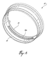
- the heat exchanger 22 includes an annular duct 30 surrounding the engine component to be cooled, here the turbine support case 92. As shown, an annular perforated baffle 32 which surrounds the turbine support case 92 is part of the heat exchanger 22.
- the duct 30 contains at least one air conduit 34a,b and at least one fuel conduit 36 which extend around the circumferential direction of the duct 30 in heat exchange relationship with one another.
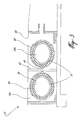
- the heat exchanger includes two fuel conduits 36, which are each defined by an annular gap between inner and outer concentric tubes 38, 40 of slightly different diameters.
- the gap measures between 0.015 inch (0.381 mm) and 0.05 inch (1.27 mm), the gap size being selected based on the fuel flow rate and heat transfer required.
- the fuel conduits 36 are retained by a radial mount 42 extending across the duct 30, from which extends a pin 44 retaining the fuel conduit 36, for example through a C-shaped member 46, to allow for thermal expansion and contraction of the conduits 36.
- the inner tube 38 is inserted in the outer tube 40 while the tubes are straight, and the tubes are then formed into the circular geometry.
- a spacer for example a wire or granular filler material, is used between the tubes 38, 40 to maintain the gap during forming. Once the tubes have been deformed, the spacer can be removed.
- the fuel conduits 36 of the heat exchanger 22 provide a fuel flow communication between a fuel source (not shown) and fuel distribution members 17 (see Fig. 1 ) of the combustor 16; in a particular embodiment, all of the fuel flow from the fuel source to the combustor 16 circulates through the heat exchanger 22.
- the quantity of fuel that is required to go through the heat exchanger 22 depends on the architecture of the fuel system and on the cooling requirements of the particular component being cooled; as such, in an alternate embodiment, only the primary flow or only the secondary flow are circulated through the heat exchanger 22.
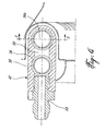
- the inlet and outlet of the fuel conduits 36 are each provided by a respective end fitting 48 (only one of which is shown) which distributes fuel to or collects fuel from all the fuel conduits 36.
- Each fitting 48 encloses a fuel channel 50 partially defined by opposed inner and outer walls 52, 54.
- the inner wall 52 includes a circular pocket 56 surrounding a circular hole 58 having an outer diameter corresponding to the inner diameter of the outer tube 40.
- the outer tube 40 is engaged in the pocket 56 and sealingly connected to the inner wall 52, for example through a brazed joint 60, while the inner tube 38 extends in the fitting 48 through the hole 58 in the inner wall 52, such as to form a fluid flow connection between the annular space between the tubes 38, 40 and the fuel channel 50.
- the outer wall 54 has a circular hole 62 through which the inner tube 38 sealingly extends, for example by connecting the inner tube 38 and the outer wall 54 through a brazed joint 60.
- a port with a connector 64 communicates with the fuel channel 50 and is designed to be complementary to end connectors of the fuel conduit (not shown) of the engine 10. This type of end fitting may facilitate visual and x-ray inspection of the joints.
- the heat exchanger 22 includes an air conduit 34a defined within the inner tube 38 of each fuel conduit 36, and a larger air conduit 34b defined by the free space in the annular duct 30 around the outer tubes 40 of the fuel conduits 36.
- the duct 30 is formed by one or more walls 66 of light weight sheet metal or other adequate light material, connected to form a closed cross-section such as to define the larger air conduit 34b. Since the heat exchanger 22 is located within the high pressure plenum 20, the pressure differential between the air conduit 34b and its surrounding environment is very small; as such, the duct 30 is not required to be made of high pressure casing material, and the thickness and weight of the wall(s) 66 can be minimized.
- the thickness of the wall(s) 66 is between 0.015 and 0.020 inches (0.381 mm and 0.508 mm); it however understood that it could be larger or smaller depending on the size of the engine or the dynamic and stress requirements. In a particular embodiment the thickness of the wall(s) is less than 0.100 inch (2.54 mm).
- the heat exchanger 22 further includes an annular wall element 68 extending from the duct 30 along an approximately axial direction.
- the wall element 68 and an adjacent portion 66a of the wall(s) 66 of the duct 30 define a cross-sectional shape which is complementary to that of the annular baffle 32, such as to together form a closed cross-section.
- the wall element 68, the adjacent portion 66a of the duct wall and the baffle 32 together define a cooling plenum 70 which surrounds an annular cavity 90 around the turbine support case 92, and is in fluid flow communication therewith through the baffle 32.
- the air conduits 34a,b define a fluid flow communication between the high pressure plenum 20 and the cooling plenum 70.
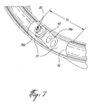
- the inlet 72 of the air conduits 34a,b is defined by an open section 74 in the duct 30 which is located in the high pressure plenum 20 and as such in direct fluid flow communication therewith.
- the end fitting 48 defining the outlet 80 of the fuel conduits 36 is preferably received in the open section 74, such as to define a counter flow heat exchanger, to reduce thermally induced stresses and maximize the heat transfer.
- the end fitting 48 defining the inlet 78 of the fuel conduits 36 ( Fig. 8 ) can alternately be received in the open section 74.
- the air is free to flow in the inner tube 38 defining the fuel conduits 36, which is left open by the end fitting 48, and is also free to flow around the outer tubes 40 defining the fuel conduits 36 into the duct 30.
- a radial wall 76 closes the end of the open section 74 opposed that through which the fuel conduits 36 extend, so that the air is directed to flow along the fuel conduits 36 around the circumference of the duct 30.
- the fuel conduits 36 extend around only part of the circumference of the duct 30.
- the duct 30 has a first arcuate portion 84 containing the fuel conduits 36 and a second arcuate portion 86 without any fuel conduits extending therethrough, the two arcuate portions 84, 86 being separated by the radial wall 76 and by the fitting 48 defining the fuel inlet 78.
- the first arcuate portion 84 extends around between approximately 240° and 315°.
- the second arcuate portion 86 is in direct fluid flow communication with the outlet 82 of the air conduits 34a,b.
- the portion 66a of the duct wall 66 located in the cooling plenum 70 and defining part of the second arcuate portion 86 includes a series of perforations 88 defined therethrough, shown here as elongated slots, to provide for the fluid flow communication between the outlets 82 of the air conduits 34a,b and the cooling plenum 70.
- the second arcuate portion 86 thus collects the cooled air and distributes it to the cooling plenum 70.
- the cooling plenum 70 draws the compressed air through the heat exchanger 22 from the high pressure plenum 20, and allows it to circulate around and through the perforated baffle 32 and to the annular cavity 90 (see Fig. 2 ) defined between the baffle 32 and the turbine support case 92.
- the perforated baffle 32 creates a pressure differential between plenum 70 and annular cavity 90. This pressure differential allows the cooled air to gain speed through the perforations of the baffle 32 to impingement cool the turbine support case 92, which carries the shroud segments 28. The turbine support case 92 is thus cooled by impingement from the air in plenum 70, passing through the perforations in the baffle 32.
- the configuration of the heat exchanger 22 and its location in the high pressure casing 20 can allow for reduced weight in comparison with a heat exchanger necessitating a high pressure casing construction. Its location around the turbine support case may also allow for a reduction in fire hazard: a fuel leak would follow the air flow and as such cause a fire around the support case, which would lead to an increase of temperature which can be easily detected and lead to shut down of the engine. Fuel leaks and fire around the turbine disks may thus be avoided.
- the fuel conduits 36 can extend around the complete perimeter of the annular duct 30 with the fuel inlet and outlet 78, 80 adjacent one another, and with the air inlet 72 and air outlet 82 remaining separately and independently defined.
- Other modifications which fall within the scope of the present invention will be apparent to those skilled in the art, in light of a review of this disclosure, and such modifications are intended to fall within the appended claims.
- separate protection may be sought in respect of the third aspect of the disclosure discussed in the SUMMARY section above.
Landscapes
- Engineering & Computer Science (AREA)
- Mechanical Engineering (AREA)
- General Engineering & Computer Science (AREA)
- Chemical & Material Sciences (AREA)
- Combustion & Propulsion (AREA)
- Heat-Exchange Devices With Radiators And Conduit Assemblies (AREA)
- Turbine Rotor Nozzle Sealing (AREA)
Applications Claiming Priority (1)
| Application Number | Priority Date | Filing Date | Title |
|---|---|---|---|
| US13/118,992 US8943827B2 (en) | 2011-05-31 | 2011-05-31 | Fuel air heat exchanger |
Publications (3)
| Publication Number | Publication Date |
|---|---|
| EP2530280A2 true EP2530280A2 (fr) | 2012-12-05 |
| EP2530280A3 EP2530280A3 (fr) | 2016-08-17 |
| EP2530280B1 EP2530280B1 (fr) | 2018-09-05 |
Family
ID=46085850
Family Applications (1)
| Application Number | Title | Priority Date | Filing Date |
|---|---|---|---|
| EP12168412.0A Active EP2530280B1 (fr) | 2011-05-31 | 2012-05-17 | Échangeur thermique d'air et de carburant |
Country Status (3)
| Country | Link |
|---|---|
| US (1) | US8943827B2 (fr) |
| EP (1) | EP2530280B1 (fr) |
| CA (1) | CA2776123C (fr) |
Cited By (1)
| Publication number | Priority date | Publication date | Assignee | Title |
|---|---|---|---|---|
| EP3026384A3 (fr) * | 2014-11-10 | 2016-08-31 | Rolls-Royce plc | Échangeur de chaleur |
Families Citing this family (39)
| Publication number | Priority date | Publication date | Assignee | Title |
|---|---|---|---|---|
| WO2013147953A1 (fr) * | 2011-12-30 | 2013-10-03 | Rolls-Royce North American Technologies Inc. | Moteur à turbine à gaz pour propulsion d'avion avec échange de chaleur |
| US9580185B2 (en) * | 2012-01-20 | 2017-02-28 | Hamilton Sundstrand Corporation | Small engine cooled cooling air system |
| US9512780B2 (en) | 2013-07-31 | 2016-12-06 | General Electric Company | Heat transfer assembly and methods of assembling the same |
| US20150159555A1 (en) * | 2013-12-10 | 2015-06-11 | Chad W. Heinrich | Internal heating using turbine air supply |
| US9995220B2 (en) * | 2013-12-20 | 2018-06-12 | Pratt & Whitney Canada Corp. | Fluid manifold for gas turbine engine and method for delivering fuel to a combustor using same |
| US10138743B2 (en) * | 2016-06-08 | 2018-11-27 | General Electric Company | Impingement cooling system for a gas turbine engine |
| US11174789B2 (en) | 2018-05-23 | 2021-11-16 | General Electric Company | Air cycle assembly for a gas turbine engine assembly |
| US10989411B2 (en) | 2019-01-03 | 2021-04-27 | General Electric Company | Heat exchanger for turbo machine |
| US11067000B2 (en) | 2019-02-13 | 2021-07-20 | General Electric Company | Hydraulically driven local pump |
| FR3099798B1 (fr) * | 2019-08-09 | 2021-12-03 | Safran Aircraft Engines | Ensemble pour une turbine de turbomachine |
| US11692479B2 (en) | 2019-10-03 | 2023-07-04 | General Electric Company | Heat exchanger with active buffer layer |
| FR3103521B1 (fr) * | 2019-11-22 | 2021-12-10 | Safran Helicopter Engines | Ensemble pour une turbomachine |
| US11480337B2 (en) | 2019-11-26 | 2022-10-25 | Collins Engine Nozzles, Inc. | Fuel injection for integral combustor and turbine vane |
| US11519368B2 (en) * | 2020-01-07 | 2022-12-06 | Raytheon Technologies Corporation | Heat exchanger supply plenum |
| US11300360B2 (en) * | 2020-01-24 | 2022-04-12 | Hamilton Sundstrand Corporation | Pressure vessel with barrier passage containing fire suppressant elements |
| US11788470B2 (en) | 2021-03-01 | 2023-10-17 | General Electric Company | Gas turbine engine thermal management |
| CN112963861B (zh) * | 2021-03-11 | 2022-08-30 | 哈尔滨工业大学 | 一种换热面积可分配式双燃料预冷器 |
| US12241424B2 (en) * | 2021-03-23 | 2025-03-04 | General Electric Company | Hydrogen fuel leak detection system |
| US11555450B1 (en) | 2021-08-19 | 2023-01-17 | Collins Engine Nozzles, Inc. | Fuel injectors with heat exchangers |
| US12637981B2 (en) | 2022-10-25 | 2026-05-26 | General Electric Company | Gas turbine engine |
| US12669084B2 (en) | 2022-11-01 | 2026-06-30 | General Electric Company | Gas turbine engine |
| US12618378B2 (en) | 2022-11-01 | 2026-05-05 | General Electric Company | Gas turbine engine |
| US12618332B2 (en) | 2022-11-01 | 2026-05-05 | General Electric Company | Gas turbine engine |
| US12535033B2 (en) | 2022-11-01 | 2026-01-27 | General Electric Company | Gas turbine engine |
| US12644386B2 (en) | 2022-11-01 | 2026-06-02 | General Electric Company | Gas turbine engine |
| US12428992B2 (en) | 2022-11-01 | 2025-09-30 | General Electric Company | Gas turbine engine |
| US12503980B2 (en) | 2022-11-01 | 2025-12-23 | General Electric Company | Gas turbine engine |
| US12674420B2 (en) | 2022-11-01 | 2026-07-07 | General Electric Company | Gas turbine engine |
| US12196131B2 (en) | 2022-11-01 | 2025-01-14 | General Electric Company | Gas turbine engine |
| US12410753B2 (en) | 2022-11-01 | 2025-09-09 | General Electric Company | Gas turbine engine |
| US12392290B2 (en) | 2022-11-01 | 2025-08-19 | General Electric Company | Gas turbine engine |
| US12662958B2 (en) | 2022-11-01 | 2026-06-23 | General Electric Company | Gas turbine engine |
| US12655802B2 (en) | 2022-11-01 | 2026-06-16 | General Electric Company | Gas turbine engine |
| US12669088B2 (en) | 2022-11-01 | 2026-06-30 | General Electric Company | Gas turbine engine |
| US12662959B2 (en) | 2022-11-01 | 2026-06-23 | General Electric Company | Gas turbine engine |
| US12655803B2 (en) | 2022-11-01 | 2026-06-16 | General Electric Company | Gas turbine engine |
| US12698722B2 (en) | 2022-11-01 | 2026-08-04 | General Electric Company | Gas turbine engine |
| US12637229B2 (en) | 2023-09-22 | 2026-05-26 | General Electric Company | Methods and apparatus for leak detection and mitigation for hydrogen fueled aircraft |
| US12540551B1 (en) | 2025-07-01 | 2026-02-03 | General Electric Company | Gas turbine engines including splittered airfoils |
Family Cites Families (19)
| Publication number | Priority date | Publication date | Assignee | Title |
|---|---|---|---|---|
| US2757907A (en) * | 1950-11-09 | 1956-08-07 | Chrysler Corp | Heat exchanger |
| US4120150A (en) | 1977-05-17 | 1978-10-17 | The United States Of America As Represented By The Secretary Of The Air Force | Compact fuel-to-air heat exchanger for jet engine application |
| GB2098719B (en) * | 1981-05-20 | 1984-11-21 | Rolls Royce | Gas turbine engine combustion apparatus |
| US5317877A (en) | 1992-08-03 | 1994-06-07 | General Electric Company | Intercooled turbine blade cooling air feed system |
| US5414992A (en) | 1993-08-06 | 1995-05-16 | United Technologies Corporation | Aircraft cooling method |
| US5619855A (en) | 1995-06-07 | 1997-04-15 | General Electric Company | High inlet mach combustor for gas turbine engine |
| US6182435B1 (en) | 1997-06-05 | 2001-02-06 | Hamilton Sundstrand Corporation | Thermal and energy management method and apparatus for an aircraft |
| JPH1193694A (ja) | 1997-09-18 | 1999-04-06 | Toshiba Corp | ガスタービンプラント |
| US6672072B1 (en) | 1998-08-17 | 2004-01-06 | General Electric Company | Pressure boosted compressor cooling system |
| US6578362B1 (en) * | 1999-05-17 | 2003-06-17 | General Electric Co. | Methods and apparatus for supplying cooling air to turbine engines |
| US6584778B1 (en) | 2000-05-11 | 2003-07-01 | General Electric Co. | Methods and apparatus for supplying cooling air to turbine engines |
| US6415595B1 (en) | 2000-08-22 | 2002-07-09 | Hamilton Sundstrand Corporation | Integrated thermal management and coolant system for an aircraft |
| US6363724B1 (en) * | 2000-08-31 | 2002-04-02 | General Electric Company | Gas only nozzle fuel tip |
| GB2389174B (en) | 2002-05-01 | 2005-10-26 | Rolls Royce Plc | Cooling systems |
| US7231769B2 (en) | 2004-01-29 | 2007-06-19 | United Technologies Corporation | Gas turbine cooling system |
| US7559201B2 (en) * | 2005-09-08 | 2009-07-14 | Pratt & Whitney Canada Corp. | Redundant fuel manifold sealing arrangement |
| US8127547B2 (en) | 2007-06-07 | 2012-03-06 | United Technologies Corporation | Gas turbine engine with air and fuel cooling system |
| US8056345B2 (en) * | 2007-06-13 | 2011-11-15 | United Technologies Corporation | Hybrid cooling of a gas turbine engine |
| DE102009026881A1 (de) * | 2009-06-10 | 2010-12-16 | Air-Lng Gmbh | Antrieb für eine Turbine nebst Antriebsverfahren |
-
2011
- 2011-05-31 US US13/118,992 patent/US8943827B2/en active Active
-
2012
- 2012-05-04 CA CA2776123A patent/CA2776123C/fr active Active
- 2012-05-17 EP EP12168412.0A patent/EP2530280B1/fr active Active
Non-Patent Citations (1)
| Title |
|---|
| None |
Cited By (2)
| Publication number | Priority date | Publication date | Assignee | Title |
|---|---|---|---|---|
| EP3026384A3 (fr) * | 2014-11-10 | 2016-08-31 | Rolls-Royce plc | Échangeur de chaleur |
| US10221768B2 (en) | 2014-11-10 | 2019-03-05 | Rolls-Royce Plc | Heat exchanger having a coaxial or concentric tube construction |
Also Published As
| Publication number | Publication date |
|---|---|
| EP2530280A3 (fr) | 2016-08-17 |
| CA2776123C (fr) | 2019-09-10 |
| CA2776123A1 (fr) | 2012-11-30 |
| US20120304662A1 (en) | 2012-12-06 |
| EP2530280B1 (fr) | 2018-09-05 |
| US8943827B2 (en) | 2015-02-03 |
Similar Documents
| Publication | Publication Date | Title |
|---|---|---|
| EP2530280B1 (fr) | Échangeur thermique d'air et de carburant | |
| US9109842B2 (en) | Fuel air heat exchanger | |
| JP6179956B2 (ja) | 熱交換器組立体(60)及びモジュール式放射状管体型熱交換器(60)を組み立てる方法 | |
| US10253696B2 (en) | Air cooled air cooler for gas turbine engine air system | |
| EP3214373B1 (fr) | Injecteur de carburant à faisceau tubulaire avec refroidissement interne | |
| EP2573329B1 (fr) | Architecture de système d'air pour un module de cadre de turbine intermédiaire | |
| EP3171088B1 (fr) | Ensemble injecteur de carburant à faisceau tubulaire ayant une capacité de combustible liquide | |
| EP2927426B1 (fr) | Système de refroidissement comprenant une dérivation de compartiment de palier et procédé correspondant | |
| US10612383B2 (en) | Compressor aft rotor rim cooling for high OPR (T3) engine | |
| CN103185354B (zh) | 用于冷却过渡喷嘴的方法和系统 | |
| US8959886B2 (en) | Mesh cooled conduit for conveying combustion gases | |
| US20060123796A1 (en) | Secondary flow, high pressure turbine module cooling air system for recuperated gas turbine engines | |
| EP2492471A2 (fr) | Récupérateur de moteur à turbine à gaz doté de connexion flottante | |
| US11280198B2 (en) | Turbine engine with annular cavity | |
| CN101178027A (zh) | 操作燃气轮机换热器的方法和装置 | |
| CN107339125A (zh) | 用于冷却燃气涡轮发动机的部件的系统和方法 | |
| EP3339609A1 (fr) | Ensemble de montage pour conduit de fluide de moteur à turbine à gaz | |
| CN105209723A (zh) | 用于燃气涡轮发动机的中框架壳体的热屏蔽歧管系统 | |
| CA3145036A1 (fr) | Refroidissement de capteur de coupe pour une turbine a gaz au moyen de l'air externe | |
| US20180209647A1 (en) | Fuel Nozzle Assembly with Fuel Purge | |
| US12345180B2 (en) | Stator plenum for a gas turbine engine | |
| EP3396247B1 (fr) | Dispositif de couvercle d'extrémité de chambre de combustion de turbomachine |
Legal Events
| Date | Code | Title | Description |
|---|---|---|---|
| PUAI | Public reference made under article 153(3) epc to a published international application that has entered the european phase |
Free format text: ORIGINAL CODE: 0009012 |
|
| AK | Designated contracting states |
Kind code of ref document: A2 Designated state(s): AL AT BE BG CH CY CZ DE DK EE ES FI FR GB GR HR HU IE IS IT LI LT LU LV MC MK MT NL NO PL PT RO RS SE SI SK SM TR |
|
| AX | Request for extension of the european patent |
Extension state: BA ME |
|
| PUAL | Search report despatched |
Free format text: ORIGINAL CODE: 0009013 |
|
| AK | Designated contracting states |
Kind code of ref document: A3 Designated state(s): AL AT BE BG CH CY CZ DE DK EE ES FI FR GB GR HR HU IE IS IT LI LT LU LV MC MK MT NL NO PL PT RO RS SE SI SK SM TR |
|
| AX | Request for extension of the european patent |
Extension state: BA ME |
|
| RIC1 | Information provided on ipc code assigned before grant |
Ipc: F01D 25/12 20060101ALI20160713BHEP Ipc: F01D 25/14 20060101ALI20160713BHEP Ipc: F02C 7/224 20060101AFI20160713BHEP |
|
| STAA | Information on the status of an ep patent application or granted ep patent |
Free format text: STATUS: REQUEST FOR EXAMINATION WAS MADE |
|
| 17P | Request for examination filed |
Effective date: 20170217 |
|
| RBV | Designated contracting states (corrected) |
Designated state(s): AL AT BE BG CH CY CZ DE DK EE ES FI FR GB GR HR HU IE IS IT LI LT LU LV MC MK MT NL NO PL PT RO RS SE SI SK SM TR |
|
| GRAP | Despatch of communication of intention to grant a patent |
Free format text: ORIGINAL CODE: EPIDOSNIGR1 |
|
| STAA | Information on the status of an ep patent application or granted ep patent |
Free format text: STATUS: GRANT OF PATENT IS INTENDED |
|
| INTG | Intention to grant announced |
Effective date: 20180315 |
|
| GRAS | Grant fee paid |
Free format text: ORIGINAL CODE: EPIDOSNIGR3 |
|
| GRAA | (expected) grant |
Free format text: ORIGINAL CODE: 0009210 |
|
| STAA | Information on the status of an ep patent application or granted ep patent |
Free format text: STATUS: THE PATENT HAS BEEN GRANTED |
|
| AK | Designated contracting states |
Kind code of ref document: B1 Designated state(s): AL AT BE BG CH CY CZ DE DK EE ES FI FR GB GR HR HU IE IS IT LI LT LU LV MC MK MT NL NO PL PT RO RS SE SI SK SM TR |
|
| REG | Reference to a national code |
Ref country code: GB Ref legal event code: FG4D |
|
| REG | Reference to a national code |
Ref country code: CH Ref legal event code: EP |
|
| REG | Reference to a national code |
Ref country code: AT Ref legal event code: REF Ref document number: 1038078 Country of ref document: AT Kind code of ref document: T Effective date: 20180915 |
|
| REG | Reference to a national code |
Ref country code: IE Ref legal event code: FG4D |
|
| REG | Reference to a national code |
Ref country code: DE Ref legal event code: R096 Ref document number: 602012050567 Country of ref document: DE |
|
| REG | Reference to a national code |
Ref country code: NL Ref legal event code: MP Effective date: 20180905 |
|
| REG | Reference to a national code |
Ref country code: LT Ref legal event code: MG4D |
|
| PG25 | Lapsed in a contracting state [announced via postgrant information from national office to epo] |
Ref country code: FI Free format text: LAPSE BECAUSE OF FAILURE TO SUBMIT A TRANSLATION OF THE DESCRIPTION OR TO PAY THE FEE WITHIN THE PRESCRIBED TIME-LIMIT Effective date: 20180905 Ref country code: LT Free format text: LAPSE BECAUSE OF FAILURE TO SUBMIT A TRANSLATION OF THE DESCRIPTION OR TO PAY THE FEE WITHIN THE PRESCRIBED TIME-LIMIT Effective date: 20180905 Ref country code: RS Free format text: LAPSE BECAUSE OF FAILURE TO SUBMIT A TRANSLATION OF THE DESCRIPTION OR TO PAY THE FEE WITHIN THE PRESCRIBED TIME-LIMIT Effective date: 20180905 Ref country code: SE Free format text: LAPSE BECAUSE OF FAILURE TO SUBMIT A TRANSLATION OF THE DESCRIPTION OR TO PAY THE FEE WITHIN THE PRESCRIBED TIME-LIMIT Effective date: 20180905 Ref country code: GR Free format text: LAPSE BECAUSE OF FAILURE TO SUBMIT A TRANSLATION OF THE DESCRIPTION OR TO PAY THE FEE WITHIN THE PRESCRIBED TIME-LIMIT Effective date: 20181206 Ref country code: NO Free format text: LAPSE BECAUSE OF FAILURE TO SUBMIT A TRANSLATION OF THE DESCRIPTION OR TO PAY THE FEE WITHIN THE PRESCRIBED TIME-LIMIT Effective date: 20181205 Ref country code: BG Free format text: LAPSE BECAUSE OF FAILURE TO SUBMIT A TRANSLATION OF THE DESCRIPTION OR TO PAY THE FEE WITHIN THE PRESCRIBED TIME-LIMIT Effective date: 20181205 |
|
| REG | Reference to a national code |
Ref country code: AT Ref legal event code: MK05 Ref document number: 1038078 Country of ref document: AT Kind code of ref document: T Effective date: 20180905 |
|
| PG25 | Lapsed in a contracting state [announced via postgrant information from national office to epo] |
Ref country code: HR Free format text: LAPSE BECAUSE OF FAILURE TO SUBMIT A TRANSLATION OF THE DESCRIPTION OR TO PAY THE FEE WITHIN THE PRESCRIBED TIME-LIMIT Effective date: 20180905 Ref country code: LV Free format text: LAPSE BECAUSE OF FAILURE TO SUBMIT A TRANSLATION OF THE DESCRIPTION OR TO PAY THE FEE WITHIN THE PRESCRIBED TIME-LIMIT Effective date: 20180905 Ref country code: AL Free format text: LAPSE BECAUSE OF FAILURE TO SUBMIT A TRANSLATION OF THE DESCRIPTION OR TO PAY THE FEE WITHIN THE PRESCRIBED TIME-LIMIT Effective date: 20180905 |
|
| PG25 | Lapsed in a contracting state [announced via postgrant information from national office to epo] |
Ref country code: CZ Free format text: LAPSE BECAUSE OF FAILURE TO SUBMIT A TRANSLATION OF THE DESCRIPTION OR TO PAY THE FEE WITHIN THE PRESCRIBED TIME-LIMIT Effective date: 20180905 Ref country code: IT Free format text: LAPSE BECAUSE OF FAILURE TO SUBMIT A TRANSLATION OF THE DESCRIPTION OR TO PAY THE FEE WITHIN THE PRESCRIBED TIME-LIMIT Effective date: 20180905 Ref country code: ES Free format text: LAPSE BECAUSE OF FAILURE TO SUBMIT A TRANSLATION OF THE DESCRIPTION OR TO PAY THE FEE WITHIN THE PRESCRIBED TIME-LIMIT Effective date: 20180905 Ref country code: RO Free format text: LAPSE BECAUSE OF FAILURE TO SUBMIT A TRANSLATION OF THE DESCRIPTION OR TO PAY THE FEE WITHIN THE PRESCRIBED TIME-LIMIT Effective date: 20180905 Ref country code: NL Free format text: LAPSE BECAUSE OF FAILURE TO SUBMIT A TRANSLATION OF THE DESCRIPTION OR TO PAY THE FEE WITHIN THE PRESCRIBED TIME-LIMIT Effective date: 20180905 Ref country code: AT Free format text: LAPSE BECAUSE OF FAILURE TO SUBMIT A TRANSLATION OF THE DESCRIPTION OR TO PAY THE FEE WITHIN THE PRESCRIBED TIME-LIMIT Effective date: 20180905 Ref country code: EE Free format text: LAPSE BECAUSE OF FAILURE TO SUBMIT A TRANSLATION OF THE DESCRIPTION OR TO PAY THE FEE WITHIN THE PRESCRIBED TIME-LIMIT Effective date: 20180905 Ref country code: IS Free format text: LAPSE BECAUSE OF FAILURE TO SUBMIT A TRANSLATION OF THE DESCRIPTION OR TO PAY THE FEE WITHIN THE PRESCRIBED TIME-LIMIT Effective date: 20190105 Ref country code: PL Free format text: LAPSE BECAUSE OF FAILURE TO SUBMIT A TRANSLATION OF THE DESCRIPTION OR TO PAY THE FEE WITHIN THE PRESCRIBED TIME-LIMIT Effective date: 20180905 |
|
| PG25 | Lapsed in a contracting state [announced via postgrant information from national office to epo] |
Ref country code: SK Free format text: LAPSE BECAUSE OF FAILURE TO SUBMIT A TRANSLATION OF THE DESCRIPTION OR TO PAY THE FEE WITHIN THE PRESCRIBED TIME-LIMIT Effective date: 20180905 Ref country code: SM Free format text: LAPSE BECAUSE OF FAILURE TO SUBMIT A TRANSLATION OF THE DESCRIPTION OR TO PAY THE FEE WITHIN THE PRESCRIBED TIME-LIMIT Effective date: 20180905 Ref country code: PT Free format text: LAPSE BECAUSE OF FAILURE TO SUBMIT A TRANSLATION OF THE DESCRIPTION OR TO PAY THE FEE WITHIN THE PRESCRIBED TIME-LIMIT Effective date: 20190105 |
|
| REG | Reference to a national code |
Ref country code: DE Ref legal event code: R097 Ref document number: 602012050567 Country of ref document: DE |
|
| PLBE | No opposition filed within time limit |
Free format text: ORIGINAL CODE: 0009261 |
|
| STAA | Information on the status of an ep patent application or granted ep patent |
Free format text: STATUS: NO OPPOSITION FILED WITHIN TIME LIMIT |
|
| PG25 | Lapsed in a contracting state [announced via postgrant information from national office to epo] |
Ref country code: DK Free format text: LAPSE BECAUSE OF FAILURE TO SUBMIT A TRANSLATION OF THE DESCRIPTION OR TO PAY THE FEE WITHIN THE PRESCRIBED TIME-LIMIT Effective date: 20180905 |
|
| 26N | No opposition filed |
Effective date: 20190606 |
|
| PG25 | Lapsed in a contracting state [announced via postgrant information from national office to epo] |
Ref country code: SI Free format text: LAPSE BECAUSE OF FAILURE TO SUBMIT A TRANSLATION OF THE DESCRIPTION OR TO PAY THE FEE WITHIN THE PRESCRIBED TIME-LIMIT Effective date: 20180905 |
|
| REG | Reference to a national code |
Ref country code: CH Ref legal event code: PL |
|
| PG25 | Lapsed in a contracting state [announced via postgrant information from national office to epo] |
Ref country code: CH Free format text: LAPSE BECAUSE OF NON-PAYMENT OF DUE FEES Effective date: 20190531 Ref country code: LI Free format text: LAPSE BECAUSE OF NON-PAYMENT OF DUE FEES Effective date: 20190531 Ref country code: MC Free format text: LAPSE BECAUSE OF FAILURE TO SUBMIT A TRANSLATION OF THE DESCRIPTION OR TO PAY THE FEE WITHIN THE PRESCRIBED TIME-LIMIT Effective date: 20180905 |
|
| REG | Reference to a national code |
Ref country code: BE Ref legal event code: MM Effective date: 20190531 |
|
| PG25 | Lapsed in a contracting state [announced via postgrant information from national office to epo] |
Ref country code: LU Free format text: LAPSE BECAUSE OF NON-PAYMENT OF DUE FEES Effective date: 20190517 |
|
| PG25 | Lapsed in a contracting state [announced via postgrant information from national office to epo] |
Ref country code: TR Free format text: LAPSE BECAUSE OF FAILURE TO SUBMIT A TRANSLATION OF THE DESCRIPTION OR TO PAY THE FEE WITHIN THE PRESCRIBED TIME-LIMIT Effective date: 20180905 |
|
| PG25 | Lapsed in a contracting state [announced via postgrant information from national office to epo] |
Ref country code: IE Free format text: LAPSE BECAUSE OF NON-PAYMENT OF DUE FEES Effective date: 20190517 |
|
| PG25 | Lapsed in a contracting state [announced via postgrant information from national office to epo] |
Ref country code: BE Free format text: LAPSE BECAUSE OF NON-PAYMENT OF DUE FEES Effective date: 20190531 |
|
| PG25 | Lapsed in a contracting state [announced via postgrant information from national office to epo] |
Ref country code: CY Free format text: LAPSE BECAUSE OF FAILURE TO SUBMIT A TRANSLATION OF THE DESCRIPTION OR TO PAY THE FEE WITHIN THE PRESCRIBED TIME-LIMIT Effective date: 20180905 |
|
| PG25 | Lapsed in a contracting state [announced via postgrant information from national office to epo] |
Ref country code: MT Free format text: LAPSE BECAUSE OF FAILURE TO SUBMIT A TRANSLATION OF THE DESCRIPTION OR TO PAY THE FEE WITHIN THE PRESCRIBED TIME-LIMIT Effective date: 20180905 Ref country code: HU Free format text: LAPSE BECAUSE OF FAILURE TO SUBMIT A TRANSLATION OF THE DESCRIPTION OR TO PAY THE FEE WITHIN THE PRESCRIBED TIME-LIMIT; INVALID AB INITIO Effective date: 20120517 |
|
| PG25 | Lapsed in a contracting state [announced via postgrant information from national office to epo] |
Ref country code: MK Free format text: LAPSE BECAUSE OF FAILURE TO SUBMIT A TRANSLATION OF THE DESCRIPTION OR TO PAY THE FEE WITHIN THE PRESCRIBED TIME-LIMIT Effective date: 20180905 |
|
| P01 | Opt-out of the competence of the unified patent court (upc) registered |
Effective date: 20230530 |
|
| PGFP | Annual fee paid to national office [announced via postgrant information from national office to epo] |
Ref country code: GB Payment date: 20260421 Year of fee payment: 15 |
|
| PGFP | Annual fee paid to national office [announced via postgrant information from national office to epo] |
Ref country code: DE Payment date: 20260421 Year of fee payment: 15 |
|
| PGFP | Annual fee paid to national office [announced via postgrant information from national office to epo] |
Ref country code: FR Payment date: 20260421 Year of fee payment: 15 |