EP2530284A2 - Motorbetriebene Drosselventilsteuervorrichtung mit induktanzbasierter kontaktfreier Drehwinkelerkennungsvorrichtung und Drehwinkelerkennungsvorrichtung dafür - Google Patents
Motorbetriebene Drosselventilsteuervorrichtung mit induktanzbasierter kontaktfreier Drehwinkelerkennungsvorrichtung und Drehwinkelerkennungsvorrichtung dafür Download PDFInfo
- Publication number
- EP2530284A2 EP2530284A2 EP12169651A EP12169651A EP2530284A2 EP 2530284 A2 EP2530284 A2 EP 2530284A2 EP 12169651 A EP12169651 A EP 12169651A EP 12169651 A EP12169651 A EP 12169651A EP 2530284 A2 EP2530284 A2 EP 2530284A2
- Authority
- EP
- European Patent Office
- Prior art keywords
- rotation angle
- conductor part
- angle detecting
- detecting device
- magnetic field
- Prior art date
- Legal status (The legal status is an assumption and is not a legal conclusion. Google has not performed a legal analysis and makes no representation as to the accuracy of the status listed.)
- Granted
Links
Images


Classifications
-
- G—PHYSICS
- G01—MEASURING; TESTING
- G01D—MEASURING NOT SPECIALLY ADAPTED FOR A SPECIFIC VARIABLE; ARRANGEMENTS FOR MEASURING TWO OR MORE VARIABLES NOT COVERED IN A SINGLE OTHER SUBCLASS; TARIFF METERING APPARATUS; MEASURING OR TESTING NOT OTHERWISE PROVIDED FOR
- G01D5/00—Mechanical means for transferring the output of a sensing member; Means for converting the output of a sensing member to another variable where the form or nature of the sensing member does not constrain the means for converting; Transducers not specially adapted for a specific variable
- G01D5/12—Mechanical means for transferring the output of a sensing member; Means for converting the output of a sensing member to another variable where the form or nature of the sensing member does not constrain the means for converting; Transducers not specially adapted for a specific variable using electric or magnetic means
- G01D5/14—Mechanical means for transferring the output of a sensing member; Means for converting the output of a sensing member to another variable where the form or nature of the sensing member does not constrain the means for converting; Transducers not specially adapted for a specific variable using electric or magnetic means influencing the magnitude of a current or voltage
- G01D5/20—Mechanical means for transferring the output of a sensing member; Means for converting the output of a sensing member to another variable where the form or nature of the sensing member does not constrain the means for converting; Transducers not specially adapted for a specific variable using electric or magnetic means influencing the magnitude of a current or voltage by varying inductance, e.g. by a movable armature
- G01D5/22—Mechanical means for transferring the output of a sensing member; Means for converting the output of a sensing member to another variable where the form or nature of the sensing member does not constrain the means for converting; Transducers not specially adapted for a specific variable using electric or magnetic means influencing the magnitude of a current or voltage by varying inductance, e.g. by a movable armature differentially influencing two coils
- G01D5/2208—Mechanical means for transferring the output of a sensing member; Means for converting the output of a sensing member to another variable where the form or nature of the sensing member does not constrain the means for converting; Transducers not specially adapted for a specific variable using electric or magnetic means influencing the magnitude of a current or voltage by varying inductance, e.g. by a movable armature differentially influencing two coils by influencing the self-induction of the coils
- G01D5/2225—Mechanical means for transferring the output of a sensing member; Means for converting the output of a sensing member to another variable where the form or nature of the sensing member does not constrain the means for converting; Transducers not specially adapted for a specific variable using electric or magnetic means influencing the magnitude of a current or voltage by varying inductance, e.g. by a movable armature differentially influencing two coils by influencing the self-induction of the coils by a movable non-ferromagnetic conductive element
-
- F—MECHANICAL ENGINEERING; LIGHTING; HEATING; WEAPONS; BLASTING
- F02—COMBUSTION ENGINES; HOT-GAS OR COMBUSTION-PRODUCT ENGINE PLANTS
- F02D—CONTROLLING COMBUSTION ENGINES
- F02D9/00—Controlling engines by throttling air or fuel-and-air induction conduits or exhaust conduits
- F02D9/08—Throttle valves specially adapted therefor; Arrangements of such valves in conduits
- F02D9/10—Throttle valves specially adapted therefor; Arrangements of such valves in conduits having pivotally-mounted flaps
-
- G—PHYSICS
- G01—MEASURING; TESTING
- G01D—MEASURING NOT SPECIALLY ADAPTED FOR A SPECIFIC VARIABLE; ARRANGEMENTS FOR MEASURING TWO OR MORE VARIABLES NOT COVERED IN A SINGLE OTHER SUBCLASS; TARIFF METERING APPARATUS; MEASURING OR TESTING NOT OTHERWISE PROVIDED FOR
- G01D5/00—Mechanical means for transferring the output of a sensing member; Means for converting the output of a sensing member to another variable where the form or nature of the sensing member does not constrain the means for converting; Transducers not specially adapted for a specific variable
- G01D5/12—Mechanical means for transferring the output of a sensing member; Means for converting the output of a sensing member to another variable where the form or nature of the sensing member does not constrain the means for converting; Transducers not specially adapted for a specific variable using electric or magnetic means
- G01D5/244—Mechanical means for transferring the output of a sensing member; Means for converting the output of a sensing member to another variable where the form or nature of the sensing member does not constrain the means for converting; Transducers not specially adapted for a specific variable using electric or magnetic means influencing characteristics of pulses or pulse trains; generating pulses or pulse trains
- G01D5/245—Mechanical means for transferring the output of a sensing member; Means for converting the output of a sensing member to another variable where the form or nature of the sensing member does not constrain the means for converting; Transducers not specially adapted for a specific variable using electric or magnetic means influencing characteristics of pulses or pulse trains; generating pulses or pulse trains using a variable number of pulses in a train
- G01D5/2451—Incremental encoders
-
- H—ELECTRICITY
- H02—GENERATION; CONVERSION OR DISTRIBUTION OF ELECTRIC POWER
- H02K—DYNAMO-ELECTRIC MACHINES
- H02K11/00—Structural association of dynamo-electric machines with electric components or with devices for shielding, monitoring or protection
- H02K11/40—Structural association with grounding devices
-
- H—ELECTRICITY
- H02—GENERATION; CONVERSION OR DISTRIBUTION OF ELECTRIC POWER
- H02K—DYNAMO-ELECTRIC MACHINES
- H02K7/00—Arrangements for handling mechanical energy structurally associated with dynamo-electric machines, e.g. structural association with mechanical driving motors or auxiliary dynamo-electric machines
- H02K7/10—Structural association with clutches, brakes, gears, pulleys or mechanical starters
- H02K7/116—Structural association with clutches, brakes, gears, pulleys or mechanical starters with gears
-
- F—MECHANICAL ENGINEERING; LIGHTING; HEATING; WEAPONS; BLASTING
- F02—COMBUSTION ENGINES; HOT-GAS OR COMBUSTION-PRODUCT ENGINE PLANTS
- F02D—CONTROLLING COMBUSTION ENGINES
- F02D9/00—Controlling engines by throttling air or fuel-and-air induction conduits or exhaust conduits
- F02D9/08—Throttle valves specially adapted therefor; Arrangements of such valves in conduits
- F02D9/10—Throttle valves specially adapted therefor; Arrangements of such valves in conduits having pivotally-mounted flaps
- F02D9/1035—Details of the valve housing
- F02D9/105—Details of the valve housing having a throttle position sensor
Definitions
- the present invention relates a noncontact rotation angle detecting device which detects the rotational position (rotation angle) of a rotating conductor by taking advantage of the phenomenon that the inductance between the rotating conductor (attached to a rotating shaft of a rotating body) and a coil conductor attached to a stator facing the rotating conductor changes according to the positional relationship between the two conductors.
- the present invention relates also to a motor-driven throttle valve control device which electrically controls the opening area of an air passage of an internal combustion engine by use of a throttle valve driven by a motor and which is equipped with the above rotation angle detecting device for detecting the rotation angle of the throttle valve.
- a rotation angle detecting device described in JP-2008-96231-A is known as an example of the so-called noncontact rotation angle detecting device that detects the position or rotation angle of a rotating body based on the change in inductance.
- a holder in a cup-like shape is attached to the tip of the object of detection of rotation, a disk made of insulating material is fixed to the end face of the holder, and an excitation conductor is printed on the surface of the disk.
- the rotation angle detecting device mainly includes three components: the disk made of insulating material on which the excitation conductor is printed, the holder which holds the excitation conductor (disk), and an inserter made of metal for fixing the holder to the object of detection of rotation (throttle shaft). Further, the disk (made of insulating material and having the excitation conductor printed thereon) and the holder for holding the disk are joined together using an adhesive agent. Thus, a large number of parts and assembling steps are necessary for the production of the rotation angle detecting device.
- the excitation conductor is configured to have a cylindrical press-in part and a planar engaging part formed continuously and integrally in the axial direction of the excitation conductor. Meanwhile, a cylindrical part and a planar part are formed continuously and integrally at the tip of the rotating shaft (throttle shaft).
- the cylindrical press-in part of the excitation conductor is directly fixed to the cylindrical part at the tip of the rotating shaft while making the planar engaging part of the excitation conductor engage with the planar part of the rotating shaft.
- a part made of insulating material is provided at the tip of the object of detection of rotation (throttle shaft) and the excitation conductor is directly attached to the part made of insulating material.
- the object of detection of rotation may be implemented by a shaft made of insulating material and the excitation conductor may be directly fixed to the shaft made of insulating material.
- a housing which supports the object of detection of rotation (throttle shaft) may be made of insulating material and the excitation conductor may be directly fixed to the object of detection of rotation (throttle shaft).
- a bearing which supports the object of detection of rotation may be formed of a member made of insulating material and the excitation conductor may be directly fixed to the object of detection of rotation (throttle shaft).
- an insulating member or an insulating layer may be provided for blocking the channel of discharge current flowing from a power supply connector (attached to a case member (gear cover)) through the magnetic field exciting conductor, the signal detection conductor and the excitation conductor (attached to the object of detection of rotation (throttle shaft)) when static electricity occurs to the power supply connector attached to the case member.
- a motor-driven throttle valve control device having an inductance-based noncontact rotation angle detecting device, not affected by electrostatic noise and having high reliability, can be realized.
- Fig. 1 is an enlarged cross-sectional view showing a principal part of an inductance-based noncontact rotation angle detecting device in accordance with a first embodiment of the present invention.
- Fig. 2 is a perspective view showing a principal part of the rotation angle detecting device.
- Fig. 3 is an exploded perspective view showing a rotating shaft and a conductor pair of the rotation angle detecting device.
- a cylindrical part 19S of a resin holder 19 has been formed integrally by plastic molding (resin molding) by using the rotating shaft 3 as an insert member.
- a disk part 19P has been formed by integral molding.
- an excitation conductor 18 (explained later) is formed integrally with the resin holder 19 when the resin holder 19 and the rotating shaft 3 are formed integrally.
- the rotating shaft 3 having a groove 301D is located inside of a plastic-molded part of the resin holder 19, by which the resin holder 19 is prevented from dropping off.
- the rotating shaft 3 is provided with planar parts 301B and 301C, by which the resin holder 19 is prevented from rotating with respect to the rotating shaft 3.
- the excitation conductor 18 is made up of linear parts 181 extending radially, arc-shaped parts 182 formed to connect inner-radius ends of adjacent linear parts 181, and arc-shaped parts 183 formed to connect peripheral ends of adjacent linear parts 181.
- Six of the linear parts 181 are arranged at 60-degree intervals.
- a sensor circuit board 103 is fixed on a sensor case 200A to face the excitation conductor 18 by using an adhesive agent.
- the top and bottom of the sensor circuit board 103 after being bonded to the sensor case 200A are coated with a coating agent, by which the sensor circuit board 103 is protected from abrasion powder and corrosive gas.
- the sensor circuit board 103 is provided with exciting conductors 3A and signal detection conductors 3B as printed wiring.
- each electric terminal 3K1 - 3K4 is bonded to the sensor circuit board 103 by brazing or welding.
- the other end of each electric terminal 3K1 - 3K4 is connected to an electric conductor which has been plastic-molded integrally with the sensor case 200A.
- each electric terminal 3K1 - 3K4 is connected to a connector (unshown) which has been plastic-molded integrally with the sensor case 200A.
- the magnetic field exciting conductors 3A are printed on an insulating substrate of the sensor circuit board 103 as shown in Fig. 2 .
- a plurality of signal detection conductors 3B are printed to extend radially.
- the back of the sensor circuit board 103 is also printed with similar exciting conductors 3A and signal detection conductors 3B.
- the magnetic field exciting conductors 3A and the signal detection conductors 3B on the two faces of the sensor circuit board 103 are connected with each other by through holes 3C - 3F.
- the sensor circuit board 103 is configured so that three-phase AC (Alternating Current) signals with 120-degree phase differences can be acquired from the signal detection conductors 3B.
- AC Alternating Current
- Two noncontact rotation angle detecting devices practically identical with each other are formed. Sensor abnormalities are detected by comparing signals from the two rotation angle detecting devices. In case of an abnormality, the two rotation angle detecting devices back up each other.
- the reference characters "3L” and "3M” represent microcomputers. Each microcomputer 3L, 3M has functions of executing driving control and signal processing of each noncontact rotation angle detecting device.
- one (3K1, for example) functions as a power supply terminal
- one (3K3, for example) functions as a ground terminal
- the remaining two (3K2 and 3K4, for example) function as signal output terminals of the two rotation angle detecting devices, respectively.
- Each microcomputer 3L, 3M supplies electric current from the power supply terminal 3K1 to the magnetic field exciting conductors 3A, detects the rotational position of the excitation conductor 18 by processing the three-phase AC current waveforms occurring in the signal detection conductors 3B, and consequently detects the rotation angle of the rotating shaft 3.
- the microcomputer 3M can basically be regarded as a component for controlling the conductor pattern sets 3A and 3B (exciting conductors 3A, signal detection conductors 3B) constituting a first rotation angle detecting device formed on the front and back of Fig. 2 .
- the microcomputer 3L can basically be regarded as a component for controlling the conductor pattern sets 3A and 3B (exciting conductors 3A, signal detection conductors 3B) constituting a second rotation angle detecting device formed on the front or back of Fig. 2 .
- Each computer 3L, 3M supplies DC current Ia from the power supply terminal 3K1 to the magnetic field exciting conductors 3A.
- phase patterns (U, V, W) for the first rotation angle detecting device and three phase patterns (U, V, W) for the second rotation angle detecting device are formed.
- the AC currents Ir of the U, V and W phases have 120-degree phase differences between each other.
- Each microcomputer 3L, 3M detects the phase shift and determines how much the excitation conductor 18 has rotated (rotation angle) based on the phase shift.
- the two signal currents of the first and second rotation angle detecting devices which are inputted from the signal detection conductors 3B to the microcomputers 3L and 3M, basically indicate the same values.
- the microcomputers 3L and 3M process the same signal currents, respectively, and output signal voltages that are inverse in the gradient and equal in the amount of variation through the signal terminals 3K1-3K4 (3K2 and 3K4, for example). These signals are those proportional to the rotation angle of the disk.
- An external device receiving the two signals monitors the signals and thereby judges whether the first and second rotation angle detecting devices are operating normally or not. When either of the rotation angle detecting devices exhibits an abnormality, the signal of the remaining detecting device is used as the control signal.
- the resin holder 19 is formed of insulating material, and thus no electric discharge due to static electricity occurs even when electrostatic noise is applied to the electric terminal of a connector. Since no discharge current flows, the aforementioned problem that the microcomputer of the throttle sensor is broken by electric discharge can be eliminated. Further, high productivity can be achieved since the resin holder 19 is plastic-molded on the rotating shaft 3.
- this embodiment directly attaching the excitation conductor to the resin holder by insert molding, welding, bonding, etc. achieves higher productivity and lower cost even when the resin holder is formed separately and thereafter pressed onto the rotating shaft.
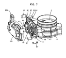
- Fig. 4 is a cross-sectional view showing the principal part of the motor-driven throttle valve control device.
- Figs. 5 - 9 are schematic diagrams for explaining the detailed structure of the motor-driven throttle valve control device.
- An air intake passage 1 (hereinafter referred to as a "bore 1") and a motor housing 20A for storing a motor 20 have been formed together in an aluminum die-cast throttle valve assembly 6 (hereinafter referred to as a "throttle body 6").
- a rotating shaft 3 made of metal (hereinafter referred to as a “throttle shaft 3”) is arranged along one diameter line of the bore 1. Both ends of the throttle shaft 3 are rotatably supported by needle bearings 9 and 10.
- the needle bearings 9 and 10 have been pressed into and fixed to bearing boss parts 7 and 8 of the throttle body 6.
- a C-shaped washer 12 (hereinafter referred to as a “thrust retainer 12") is attached to a slit part at an end of the throttle shaft 3 and thereafter the needle bearing 9 is pressed onto the slit part, by which the movement (movable range) of the throttle shaft 3 in its axial direction is restricted.
- the throttle shaft 3 is supported to be rotatable with respect to the throttle body 6.
- a throttle valve 2 implemented by a metal disk is inserted into a slit formed through the throttle shaft 3 and fixed to the throttle shaft 3 with screws 4 and 5.
- the throttle valve 2 rotates according to the rotation of the throttle shaft 3. Consequently, the cross-sectional area of the air intake passage is changed and the flow rate of the intake air supplied to the engine is controlled.
- the motor housing 20A is formed substantially in parallel with the throttle shaft 3.
- the motor 20 (implemented by a brush-type DC motor) is inserted into the motor housing 20A and fixed by screwing a flange part of a bracket 20B of the motor 20 to a side wall 6A of the throttle body 6 with screws 21.
- a wave washer 25 arranged at an end of the motor 20 holds the motor 20.
- Openings of the bearing boss parts 7 and 8 are sealed up with the needle bearings 9 and 10 so as to form a shaft seal part and maintain hermeticity.
- An end of the throttle shaft 3 where the bearing boss part 8 is arranged is sealed up with a cap 11, by which the end of the throttle shaft 3 and the needle bearing 10 are prevented from being exposed.
- An output gear 22 made of metal and having the smallest number of cogs is fixed to the end of a rotating shaft of the motor 20.
- a spring mechanism and a reduction gear mechanism for driving and rotating the throttle shaft 3 are arranged together in a lateral part of the throttle body 6 where the output gear 22 is arranged.
- These mechanisms are covered with a cover 26 made of resin (hereinafter referred to as a "gear cover 26") which is fixed to the lateral part of the throttle body 6.
- the inductance-based noncontact rotation angle detecting device which has been explained referring to Figs.
- a throttle sensor is installed in the space covered with the gear cover 26 (so-called “gear chamber”), detects the rotation angle of the throttle shaft 3, and consequently detects the open angle of the throttle valve 2.
- a throttle gear 13 is fixed to an end of the throttle shaft 3 on the gear cover 26 side.
- the throttle gear 13 is made up of a metal plate 14 and a resin gear part 15 plastic-molded on the metal plate 14.
- the metal plate 14 has a concave part in a cup-like shape at its center.
- the concave part has a flange part for the gear molding at its open end.
- the resin gear part 15 has been molded on the flange part by plastic molding.
- the metal plate 14 has a hole at the center of the concave part. A thread groove has been formed around the tip (i.e., the aforementioned end) of the throttle shaft 3.
- the metal plate 14 is fixed to the throttle shaft 3 by inserting the tip of the throttle shaft 3 into the hole of the concave part of the metal plate 14 and attaching a nut 17 to the threaded part. With this configuration, the metal plate 14 and the resin gear part 15 formed on the metal plate 14 rotate integrally with the throttle shaft 3.
- a return spring 16 formed with a helical spring is sandwiched between the back of the throttle gear 13 and the side wall of the throttle body 6.
- One end of the return spring 16, surrounding the bearing boss part 7, is fixed to a notch formed on the throttle body 6 so that the end cannot rotate in the rotational direction of the throttle shaft 3.
- the other end of the return spring 16, surrounding the cup-shaped part of the metal plate 14 of the throttle gear 13, is fixed to a hole formed through the metal plate 14 so that the end cannot rotate in the rotational direction either.
- the initial position of the throttle valve 2 (i.e., open angle position assigned to the throttle valve 2 when the power of the motor 20 is OFF) is the full-open position.
- the intermediate gear 23 is made up of a large-diameter gear 23A for engaging with the output gear 22 and a small-diameter gear 23B for engaging with the throttle gear 13.
- the large-diameter gear 23A and the small-diameter gear 23B are formed integrally by plastic molding.
- the reducing gear mechanism and the spring mechanism are covered by the gear cover 26 made of resin.
- a groove for a sealing member 30 to be inserted therein is formed on the rim of the open end of the gear cover 26.
- the rotation angle detecting device i.e., throttle sensor
- the rotation angle detecting device formed between the reducing gear mechanism configured as above and the gear cover 26 covering the reducing gear mechanism, will be explained more specifically below.
- the resin holder 19 is fixed to the end of the throttle shaft 3 on the gear cover's side by integral molding.
- the excitation conductor 18 formed by press work is attached to the plain part at the end of the resin holder 19 by integral molding.
- a magnetic field exciting conductor 28 and a signal detection conductor 29 of the throttle sensor are fixed on the gear cover 26 at positions facing the excitation conductor 18.
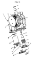
- Fig. 8 is a plan view of the gear chamber.
- the gear chamber is partitioned by the frame to which the gear cover 26 is fixed. Inside the frame, six fixation parts used for fixing the gear cover 26 with the clips can be seen.
- the reference characters "6P1" - "6P3" represent walls for positioning the gear cover 26. Positioning bosses of the gear cover 26 engage with the three walls 6P1 - 6P3, by which the magnetic field exciting conductor 28 and the signal detection conductor 29 are positioned precisely with respect to the conductor on the rotating side and allowed to output signals within a requested permissible range.
- a full-open stopper 13A as a part for mechanically setting the initial position (i.e., the full-open position) of the throttle gear 13, is implemented by a protrusion formed integrally with the side wall of the throttle body 6.
- An end of a notch of the throttle gear 13 makes contact with the protrusion (full-open stopper 13A), by which the throttle shaft 3 is prohibited from rotating across the full-open position.
- a fully-closed stopper 13B is a part for regulating the fully-closed position of the throttle shaft 3.
- the other end of the throttle gear 13 collides with the fully-closed stopper 13B, by which the throttle shaft 3 is stopped from rotating across the fully-closed position.
- Output values of the signal detection conductor (corresponding to those indicated with the reference character “3B” in Fig. 2 ) when the throttle shaft 3 is at the stopper positions represent a fully-closed value and a full-open value.
- the reference character “20B” represents a motor bracket and “20F” represents a flange part of the motor bracket 20B.
- the resin holder 19 is arranged between the excitation conductor 18 and the throttle shaft 3. With this configuration, the excitation conductor 18 and the throttle shaft 3 are insulated from each other and the above problem is resolved.
- the height of the excitation conductor 18 can be adjusted by forming the resin holder 19 by the integral molding after the throttle shaft 3 has been attached to the throttle body 6. This enables precise adjustment of the small clearances between the excitation conductor 18 and the magnetic field exciting conductor 28 and between the excitation conductor 18 and the signal detection conductor 29, by which a high-precision noncontact rotation angle detecting device can be realized.
- the attaching of the excitation conductor 18 to the resin holder 19 may be conducted by any one of the following methods:
- the welding may be conducted by any method selected from thermal welding, vibration welding and laser welding.
- the resin holder 19 is formed of insulating material, and thus no electric discharge due to static electricity occurs even when electrostatic noise is applied to an electric terminal of the connector 26A of the gear cover 26. Since no discharge current flows, the problem that the microcomputer of the throttle sensor is broken by electric discharge can be eliminated. Further, high productivity can be achieved since the resin holder is plastic-molded on the rotating shaft.
- this embodiment directly attaching the excitation conductor to the resin holder by insert molding, welding, bonding, etc. achieves higher productivity and lower cost even when the resin holder is formed separately and thereafter pressed onto the rotating shaft.
- Fig. 10 shows a rotation angle detecting device in accordance with a second embodiment of the present invention. This embodiment differs from the first embodiment in that the joining of the resin holder 19 and the throttle shaft 3 is conducted via an inserter 31 made of metal.
- the resin holder 19 and the inserter 31 have previously been formed integrally. After the throttle shaft 3 has been attached to the throttle body 6, the inserter 31 and the throttle shaft 3 are set in a press-fitting relationship, by which the resin holder 19 is fixed with respect to the throttle shaft 3.
- a high-precision noncontact rotation angle detecting device can be obtained by adjusting the height of the excitation conductor 18 during the press fitting operation.
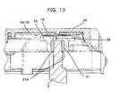
- Fig. 13 shows a rotation angle detecting device in accordance with a third embodiment of the present invention.
- This embodiment differs from the second embodiment in that the electrical path from the excitation conductor 18 to the throttle shaft 3 is eliminated by setting the distance 35 between the excitation conductor 18 (arranged on the resin holder 19) and the throttle shaft 3 at 2 mm or longer.
- this configuration no induced current flows through the excitation conductor 18 even when electrostatic noise from outside flows into the magnetic field exciting conductor 28. Consequently, the breakage of the microcomputer caused by the occurrence of electric discharge between the excitation conductor 18 and the magnetic field exciting conductor 28 or between the excitation conductor 18 and the signal detection conductor 29 can be prevented.
- the excitation conductor 18 may be formed by press work, directly printed on the resin holder 19, or formed on a printed circuit board.
- the excitation conductor 18 and the resin holder 19 may be fixed together by integral molding, or the excitation conductor 18 may be fixed to the resin holder 19 by thermal welding, vibration welding, laser welding, etc.
- the resin holder 19 and the inserter 31 have been fixed together by integral molding.
- the inserter 31 and the throttle shaft 3 are fixed together by pressing the throttle shaft 3 into the inserter 31, or by welding.
- the inserter 31 may be formed like a pin with a structure for preventing it from coming off from the resin holder 19 and fixed to the throttle shaft 3 by directly pressing it into the throttle shaft 3 or by welding.
- Table 1 shows the result of an experiment conducted for checking whether output voltages (TPS GND, TPS Vref, TPS OUT) of the signal detection conductor 29 indicate normal values when voltage is applied to the magnetic field exciting conductor 28.
- the distance between the magnetic field exciting conductor 28 and the excitation conductor 18 (dim. A shown in Fig. 17 ) was fixed at 1.2 mm and the distance between the excitation conductor 18 and the throttle shaft 3 (dim. B shown in Fig. 17 ) was changed.
- the output voltages of the signal detection conductor 29 remained within normal ranges even when a voltage of 28 kV was applied to the magnetic field exciting conductor 28.
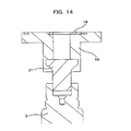
- Fig. 15 is an enlarged cross-sectional view showing a principal part of a rotation angle detecting device in accordance with a fourth embodiment of the present invention.
- the excitation conductor 18 is arranged at a resin part of the throttle gear 13.
- the excitation conductor 18 is formed by press work to have a protruding part for being joined to the throttle gear 13.
- the excitation conductor 18 may be joined to a resin-made throttle gear 13 by plastic molding. It is also possible as shown in Fig. 16 to provide the throttle gear 13 with positioning holes 13E - 13G, insert arms 18A - 18C of the excitation conductor 18 (formed by press work) into the positioning holes 13E - 13G, and join the excitation conductor 18 and the throttle gear 13 together by thermal welding, vibration welding, laser welding, etc.
- the metal plate 14 has a hole at its center similarly to the example shown in Fig. 4 .
- a thread groove has been formed around the tip of the throttle shaft 3.
- the metal plate 14 is fixed to the throttle shaft 3 by inserting the tip of the throttle shaft 3 into the hole of the metal plate 14 and attaching a nut 17 to the threaded part of the throttle shaft 3. With this configuration, the metal plate 14 and the resin gear part 15 formed on the metal plate 14 rotate integrally with the throttle
- the electrical path from the throttle shaft 3 to an external member to which the throttle body 6 is attached is eliminated in the example of Fig. 4 by changing the material of the throttle body 6 to resin or ceramic.
- the electrical path from the excitation conductor 18 to the throttle body 6 is eliminated in the example of Fig. 4 by coating the throttle shaft 3 with resin or ceramic.
- the electrical path from the excitation conductor 18 to the throttle body 6 is eliminated in the example of Fig. 4 by coating parts of the throttle shaft 3 (parts contacting the needle bearings 9 and 10 and the thrust retainer 12) with resin or ceramic.
- the electrical path from the throttle shaft 3 to the throttle body 6 is eliminated in the example of Fig. 4 by coating the needle bearings 9 and 10 and the thrust retainer 12 with resin or ceramic.
- the thrust retainer 12 having the function of regulating the position of the throttle shaft 3 in the thrust direction, can be left out by using ball bearings for the needle bearings 9 and 10.
- Fig. 11 is an enlarged cross-sectional view showing a principal part of a rotation angle detecting device in accordance with a ninth embodiment of the present invention.
- an insulator 32 is arranged between the excitation conductor 18 and the magnetic field exciting conductor 28 and signal detection conductor 29.
- the breakage of the microcomputer caused by the occurrence of electric discharge between the excitation conductor 18 and the magnetic field exciting conductor 28 or between the excitation conductor 18 and the signal detection conductor 29 due to electrostatic noise can be prevented.
- Fig. 12 is a conceptual diagram for explaining a rotation angle detecting device in accordance with a tenth embodiment of the present invention.
- the ground terminal 33 of the gear cover 26 and the gear shaft 24 are connected with each other with a conductor 34.
- the conductor 34 may either be a lead (conducting wire) or a different metallic conductor such as a spring. It is also possible to embed a member having capacitance (e.g., capacitor) in the conductor.
- inductance-based noncontact rotation angle detecting devices in accordance with the present invention were installed in motor-driven throttle valve control devices for diesel engine vehicles in the above embodiments, the present invention is applicable also to motor-driven throttle valve control devices for gasoline engine vehicles.
- the present invention is applicable to various kinds of rotation angle sensors, such as those for detecting the rotation angle of the accelerator pedal.
- the present invention is applicable also to a rotation angle detecting device for detecting the rotation angle of an actuator for controlling the movable vanes of a turbocharger.
- the present invention is applicable also to a rotation angle detecting device for detecting the rotation angle of a gear shift actuator of an automatic transmission.
- the present invention is applicable also to a rotation angle detecting device for detecting the rotation angle of a 2WD/4WD switching actuator.
Landscapes
- Engineering & Computer Science (AREA)
- Physics & Mathematics (AREA)
- General Physics & Mathematics (AREA)
- Chemical & Material Sciences (AREA)
- Combustion & Propulsion (AREA)
- Mechanical Engineering (AREA)
- General Engineering & Computer Science (AREA)
- Power Engineering (AREA)
- Measurement Of Length, Angles, Or The Like Using Electric Or Magnetic Means (AREA)
- Transmission And Conversion Of Sensor Element Output (AREA)
Applications Claiming Priority (1)
| Application Number | Priority Date | Filing Date | Title |
|---|---|---|---|
| JP2011119846A JP2012247323A (ja) | 2011-05-30 | 2011-05-30 | インダクタンス式回転角度検出装置及びそれを備えたモータ駆動式の絞り弁制御装置 |
Publications (3)
| Publication Number | Publication Date |
|---|---|
| EP2530284A2 true EP2530284A2 (de) | 2012-12-05 |
| EP2530284A3 EP2530284A3 (de) | 2013-06-05 |
| EP2530284B1 EP2530284B1 (de) | 2015-04-29 |
Family
ID=46149312
Family Applications (1)
| Application Number | Title | Priority Date | Filing Date |
|---|---|---|---|
| EP20120169651 Not-in-force EP2530284B1 (de) | 2011-05-30 | 2012-05-25 | Motorbetriebene Drosselventilsteuervorrichtung mit induktanzbasierter kontaktfreier Drehwinkelerkennungsvorrichtung und Drehwinkelerkennungsvorrichtung dafür |
Country Status (4)
| Country | Link |
|---|---|
| US (1) | US20120304964A1 (de) |
| EP (1) | EP2530284B1 (de) |
| JP (1) | JP2012247323A (de) |
| CN (1) | CN102808982B (de) |
Cited By (5)
| Publication number | Priority date | Publication date | Assignee | Title |
|---|---|---|---|---|
| WO2016065275A1 (en) * | 2014-10-24 | 2016-04-28 | Moog Inc. | Position sensor assembly |
| FR3103978A1 (fr) * | 2019-12-03 | 2021-06-04 | Faurecia Systemes D'echappement | Actionneur électrique, ensemble, ligne d’échappement et véhicule comportant un tel actionneur |
| EP3842734A4 (de) * | 2018-08-23 | 2022-04-06 | Mikuni Corporation | Elektronisch gesteuerte drosselvorrichtung für einen motor |
| WO2022243384A1 (de) * | 2021-05-19 | 2022-11-24 | Vitesco Technologies GmbH | Ventilanordnung |
| US12281625B2 (en) * | 2022-10-06 | 2025-04-22 | Mikuni Corporation | Valve device |
Families Citing this family (16)
| Publication number | Priority date | Publication date | Assignee | Title |
|---|---|---|---|---|
| US8905000B2 (en) * | 2011-12-22 | 2014-12-09 | Continental Automotive Systems, Inc. | Throttle body assembly |
| JP2015125086A (ja) * | 2013-12-27 | 2015-07-06 | 日立オートモティブシステムズ株式会社 | インダクタンス式回転角度検出装置及びそれを備えたモータ駆動式の絞り弁制御装置 |
| DE102014220454A1 (de) * | 2014-10-09 | 2016-04-14 | Robert Bosch Gmbh | Sensoranordnung zur berührungslosen Erfassung von Drehwinkeln an einem rotierenden Bauteil |
| US10627199B1 (en) | 2014-10-29 | 2020-04-21 | Moog Inc. | Active cooling system for electronics on a missile |
| JP2017067580A (ja) * | 2015-09-30 | 2017-04-06 | 日立オートモティブシステムズ株式会社 | インダクタンス式の非接触型回転角度検出装置、およびこれを備えたモータ駆動式の絞り弁制御装置 |
| JP6542661B2 (ja) * | 2015-12-28 | 2019-07-10 | 日立オートモティブシステムズ株式会社 | 内燃機関のバルブタイミング制御装置 |
| JP2017142100A (ja) * | 2016-02-09 | 2017-08-17 | 日立オートモティブシステムズ株式会社 | 回転角度検出装置及びそれを備えた絞り弁制御装置 |
| JP6594811B2 (ja) * | 2016-03-23 | 2019-10-23 | 株式会社ケーヒン | インダクティブセンサー用ローターユニット |
| CN108132679B (zh) * | 2016-12-01 | 2020-08-11 | 杭州三花研究院有限公司 | 流量控制装置及其控制系统、控制方法 |
| JP6862479B2 (ja) | 2017-02-17 | 2021-04-21 | 日立Astemo株式会社 | バルブ装置 |
| JP6759134B2 (ja) * | 2017-03-16 | 2020-09-23 | 株式会社ケーヒン | 回転検出装置 |
| US10711710B2 (en) * | 2018-05-08 | 2020-07-14 | Continental Powertrain USA, LLC | Reduced material spigot design for integrated VDA adapter housing with as-cast anti-rotation feature |
| JP2020112089A (ja) * | 2019-01-11 | 2020-07-27 | 株式会社ニッキ | 内燃機関の電子制御スロットル装置 |
| JP2021076530A (ja) * | 2019-11-12 | 2021-05-20 | 愛三工業株式会社 | バルブ装置及びバルブ装置を搭載するシステム |
| JP7400509B2 (ja) * | 2020-02-04 | 2023-12-19 | ヤマハ株式会社 | フェーダ装置 |
| JP2023114214A (ja) * | 2022-02-04 | 2023-08-17 | 株式会社ミクニ | エンジンのスロットル装置 |
Citations (1)
| Publication number | Priority date | Publication date | Assignee | Title |
|---|---|---|---|---|
| JP2008096231A (ja) | 2006-10-11 | 2008-04-24 | Hitachi Ltd | インダクタンス式回転角度検出装置及びそれを備えたモータ駆動式の絞り弁制御装置 |
Family Cites Families (4)
| Publication number | Priority date | Publication date | Assignee | Title |
|---|---|---|---|---|
| JP4001989B2 (ja) * | 1996-11-29 | 2007-10-31 | ドクトル・ヨハネス・ハイデンハイン・ゲゼルシヤフト・ミツト・ベシユレンクテル・ハフツング | 位置測定装置の走査部材 |
| JP4687540B2 (ja) * | 2006-04-12 | 2011-05-25 | 株式会社デンソー | 流体制御弁 |
| DE102007015524A1 (de) * | 2007-03-30 | 2008-10-09 | Cherry Gmbh | Verfahren zum Herstellen eines induktiven Bedämpfungselements und induktives Wirbelstrombetätigungselement |
| JP5066142B2 (ja) * | 2009-06-18 | 2012-11-07 | 日立オートモティブシステムズ株式会社 | インダクティブ型スロットルセンサ付きモータ駆動型スロットルバルブ装置、およびモータ駆動型スロットルバルブ装置のスロットルシャフトの回転角度を検出するためのインダクティブ型スロットルセンサ |
-
2011
- 2011-05-30 JP JP2011119846A patent/JP2012247323A/ja active Pending
-
2012
- 2012-05-21 CN CN201210158676.4A patent/CN102808982B/zh active Active
- 2012-05-25 EP EP20120169651 patent/EP2530284B1/de not_active Not-in-force
- 2012-05-29 US US13/482,141 patent/US20120304964A1/en not_active Abandoned
Patent Citations (1)
| Publication number | Priority date | Publication date | Assignee | Title |
|---|---|---|---|---|
| JP2008096231A (ja) | 2006-10-11 | 2008-04-24 | Hitachi Ltd | インダクタンス式回転角度検出装置及びそれを備えたモータ駆動式の絞り弁制御装置 |
Cited By (9)
| Publication number | Priority date | Publication date | Assignee | Title |
|---|---|---|---|---|
| WO2016065275A1 (en) * | 2014-10-24 | 2016-04-28 | Moog Inc. | Position sensor assembly |
| AU2015335646B2 (en) * | 2014-10-24 | 2018-11-08 | Moog Inc. | Position sensor assembly |
| US10436609B2 (en) | 2014-10-24 | 2019-10-08 | Moog Inc. | Position sensor assembly |
| EP3842734A4 (de) * | 2018-08-23 | 2022-04-06 | Mikuni Corporation | Elektronisch gesteuerte drosselvorrichtung für einen motor |
| FR3103978A1 (fr) * | 2019-12-03 | 2021-06-04 | Faurecia Systemes D'echappement | Actionneur électrique, ensemble, ligne d’échappement et véhicule comportant un tel actionneur |
| US11530756B2 (en) | 2019-12-03 | 2022-12-20 | Faurecia Systemes D'echappement | Electric actuator, assembly, exhaust line and vehicle comprising said actuator |
| WO2022243384A1 (de) * | 2021-05-19 | 2022-11-24 | Vitesco Technologies GmbH | Ventilanordnung |
| US12595853B2 (en) | 2021-05-19 | 2026-04-07 | Vitesco Technologies GmbH | Valve arrangement |
| US12281625B2 (en) * | 2022-10-06 | 2025-04-22 | Mikuni Corporation | Valve device |
Also Published As
| Publication number | Publication date |
|---|---|
| JP2012247323A (ja) | 2012-12-13 |
| EP2530284A3 (de) | 2013-06-05 |
| CN102808982A (zh) | 2012-12-05 |
| CN102808982B (zh) | 2016-06-22 |
| EP2530284B1 (de) | 2015-04-29 |
| US20120304964A1 (en) | 2012-12-06 |
Similar Documents
| Publication | Publication Date | Title |
|---|---|---|
| EP2530284A2 (de) | Motorbetriebene Drosselventilsteuervorrichtung mit induktanzbasierter kontaktfreier Drehwinkelerkennungsvorrichtung und Drehwinkelerkennungsvorrichtung dafür | |
| EP1914520B1 (de) | Induktiver Drehwinkelsensor und motorbetriebene Luftstromsteuerungsvorrichtung damit | |
| US7193343B2 (en) | Electric motor | |
| KR20040007471A (ko) | 전기 모터, 특히 전자식으로 정류되는 dc 모터용 릴레이지지 디바이스 | |
| JP5066142B2 (ja) | インダクティブ型スロットルセンサ付きモータ駆動型スロットルバルブ装置、およびモータ駆動型スロットルバルブ装置のスロットルシャフトの回転角度を検出するためのインダクティブ型スロットルセンサ | |
| US20150337743A1 (en) | Electronic Throttle Body Assembly | |
| JP5193842B2 (ja) | インダクタンス式回転角度検出装置とその製造方法、及びそれを備えたモータ駆動式の絞り弁制御装置 | |
| JP2019124527A (ja) | 回転角度検出装置および絞り弁制御装置 | |
| US20240055930A1 (en) | Electronic control device | |
| CN111162641B (zh) | 控制装置以及马达装置 | |
| EP1589638A1 (de) | Elektromotoreinheit mit steuerung | |
| JP5450511B2 (ja) | インダクタンス式回転角度検出装置及びそれを備えたモータ駆動式の絞り弁制御装置 | |
| US20060181166A1 (en) | Electric motor unit with controller | |
| CN112424460B (zh) | 电控节气门装置 | |
| JP4635924B2 (ja) | 吸気モジュール | |
| JP2015125086A (ja) | インダクタンス式回転角度検出装置及びそれを備えたモータ駆動式の絞り弁制御装置 | |
| JP2017142100A (ja) | 回転角度検出装置及びそれを備えた絞り弁制御装置 | |
| CN111756188A (zh) | 马达以及位置跟踪系统 | |
| KR20140145491A (ko) | 전동 펌프 | |
| JP2017067580A (ja) | インダクタンス式の非接触型回転角度検出装置、およびこれを備えたモータ駆動式の絞り弁制御装置 | |
| JP2011002312A (ja) | インダクタンス式回転角度検出装置及びそれを備えたモータ駆動式の絞り弁制御装置 | |
| CN121175913A (zh) | 具有布置在定子壳体中的电子电路板的电机 | |
| WO2024034114A1 (ja) | 絞り弁制御装置および圧入構造 | |
| CN121098043A (zh) | 电路一体型马达 |
Legal Events
| Date | Code | Title | Description |
|---|---|---|---|
| PUAI | Public reference made under article 153(3) epc to a published international application that has entered the european phase |
Free format text: ORIGINAL CODE: 0009012 |
|
| 17P | Request for examination filed |
Effective date: 20120914 |
|
| AK | Designated contracting states |
Kind code of ref document: A2 Designated state(s): AL AT BE BG CH CY CZ DE DK EE ES FI FR GB GR HR HU IE IS IT LI LT LU LV MC MK MT NL NO PL PT RO RS SE SI SK SM TR |
|
| AX | Request for extension of the european patent |
Extension state: BA ME |
|
| PUAL | Search report despatched |
Free format text: ORIGINAL CODE: 0009013 |
|
| AK | Designated contracting states |
Kind code of ref document: A3 Designated state(s): AL AT BE BG CH CY CZ DE DK EE ES FI FR GB GR HR HU IE IS IT LI LT LU LV MC MK MT NL NO PL PT RO RS SE SI SK SM TR |
|
| AX | Request for extension of the european patent |
Extension state: BA ME |
|
| RIC1 | Information provided on ipc code assigned before grant |
Ipc: G01D 5/20 20060101ALI20130502BHEP Ipc: G01B 7/30 20060101ALI20130502BHEP Ipc: F02D 9/10 20060101AFI20130502BHEP |
|
| GRAP | Despatch of communication of intention to grant a patent |
Free format text: ORIGINAL CODE: EPIDOSNIGR1 |
|
| INTG | Intention to grant announced |
Effective date: 20141112 |
|
| GRAS | Grant fee paid |
Free format text: ORIGINAL CODE: EPIDOSNIGR3 |
|
| GRAA | (expected) grant |
Free format text: ORIGINAL CODE: 0009210 |
|
| AK | Designated contracting states |
Kind code of ref document: B1 Designated state(s): AL AT BE BG CH CY CZ DE DK EE ES FI FR GB GR HR HU IE IS IT LI LT LU LV MC MK MT NL NO PL PT RO RS SE SI SK SM TR |
|
| REG | Reference to a national code |
Ref country code: GB Ref legal event code: FG4D |
|
| REG | Reference to a national code |
Ref country code: CH Ref legal event code: EP |
|
| REG | Reference to a national code |
Ref country code: AT Ref legal event code: REF Ref document number: 724578 Country of ref document: AT Kind code of ref document: T Effective date: 20150515 |
|
| REG | Reference to a national code |
Ref country code: IE Ref legal event code: FG4D |
|
| REG | Reference to a national code |
Ref country code: DE Ref legal event code: R096 Ref document number: 602012006962 Country of ref document: DE Effective date: 20150611 |
|
| PGFP | Annual fee paid to national office [announced via postgrant information from national office to epo] |
Ref country code: DE Payment date: 20150531 Year of fee payment: 4 |
|
| REG | Reference to a national code |
Ref country code: NL Ref legal event code: VDEP Effective date: 20150429 |
|
| REG | Reference to a national code |
Ref country code: AT Ref legal event code: MK05 Ref document number: 724578 Country of ref document: AT Kind code of ref document: T Effective date: 20150429 |
|
| REG | Reference to a national code |
Ref country code: LT Ref legal event code: MG4D |
|
| PG25 | Lapsed in a contracting state [announced via postgrant information from national office to epo] |
Ref country code: NL Free format text: LAPSE BECAUSE OF FAILURE TO SUBMIT A TRANSLATION OF THE DESCRIPTION OR TO PAY THE FEE WITHIN THE PRESCRIBED TIME-LIMIT Effective date: 20150429 |
|
| PG25 | Lapsed in a contracting state [announced via postgrant information from national office to epo] |
Ref country code: PT Free format text: LAPSE BECAUSE OF FAILURE TO SUBMIT A TRANSLATION OF THE DESCRIPTION OR TO PAY THE FEE WITHIN THE PRESCRIBED TIME-LIMIT Effective date: 20150831 Ref country code: HR Free format text: LAPSE BECAUSE OF FAILURE TO SUBMIT A TRANSLATION OF THE DESCRIPTION OR TO PAY THE FEE WITHIN THE PRESCRIBED TIME-LIMIT Effective date: 20150429 Ref country code: ES Free format text: LAPSE BECAUSE OF FAILURE TO SUBMIT A TRANSLATION OF THE DESCRIPTION OR TO PAY THE FEE WITHIN THE PRESCRIBED TIME-LIMIT Effective date: 20150429 Ref country code: LT Free format text: LAPSE BECAUSE OF FAILURE TO SUBMIT A TRANSLATION OF THE DESCRIPTION OR TO PAY THE FEE WITHIN THE PRESCRIBED TIME-LIMIT Effective date: 20150429 Ref country code: NO Free format text: LAPSE BECAUSE OF FAILURE TO SUBMIT A TRANSLATION OF THE DESCRIPTION OR TO PAY THE FEE WITHIN THE PRESCRIBED TIME-LIMIT Effective date: 20150729 Ref country code: FI Free format text: LAPSE BECAUSE OF FAILURE TO SUBMIT A TRANSLATION OF THE DESCRIPTION OR TO PAY THE FEE WITHIN THE PRESCRIBED TIME-LIMIT Effective date: 20150429 |
|
| PG25 | Lapsed in a contracting state [announced via postgrant information from national office to epo] |
Ref country code: LV Free format text: LAPSE BECAUSE OF FAILURE TO SUBMIT A TRANSLATION OF THE DESCRIPTION OR TO PAY THE FEE WITHIN THE PRESCRIBED TIME-LIMIT Effective date: 20150429 Ref country code: GR Free format text: LAPSE BECAUSE OF FAILURE TO SUBMIT A TRANSLATION OF THE DESCRIPTION OR TO PAY THE FEE WITHIN THE PRESCRIBED TIME-LIMIT Effective date: 20150730 Ref country code: RS Free format text: LAPSE BECAUSE OF FAILURE TO SUBMIT A TRANSLATION OF THE DESCRIPTION OR TO PAY THE FEE WITHIN THE PRESCRIBED TIME-LIMIT Effective date: 20150429 Ref country code: IS Free format text: LAPSE BECAUSE OF FAILURE TO SUBMIT A TRANSLATION OF THE DESCRIPTION OR TO PAY THE FEE WITHIN THE PRESCRIBED TIME-LIMIT Effective date: 20150829 Ref country code: AT Free format text: LAPSE BECAUSE OF FAILURE TO SUBMIT A TRANSLATION OF THE DESCRIPTION OR TO PAY THE FEE WITHIN THE PRESCRIBED TIME-LIMIT Effective date: 20150429 |
|
| REG | Reference to a national code |
Ref country code: CH Ref legal event code: PL |
|
| PG25 | Lapsed in a contracting state [announced via postgrant information from national office to epo] |
Ref country code: IT Free format text: LAPSE BECAUSE OF FAILURE TO SUBMIT A TRANSLATION OF THE DESCRIPTION OR TO PAY THE FEE WITHIN THE PRESCRIBED TIME-LIMIT Effective date: 20150429 Ref country code: LI Free format text: LAPSE BECAUSE OF NON-PAYMENT OF DUE FEES Effective date: 20150531 Ref country code: MC Free format text: LAPSE BECAUSE OF FAILURE TO SUBMIT A TRANSLATION OF THE DESCRIPTION OR TO PAY THE FEE WITHIN THE PRESCRIBED TIME-LIMIT Effective date: 20150429 Ref country code: DK Free format text: LAPSE BECAUSE OF FAILURE TO SUBMIT A TRANSLATION OF THE DESCRIPTION OR TO PAY THE FEE WITHIN THE PRESCRIBED TIME-LIMIT Effective date: 20150429 Ref country code: EE Free format text: LAPSE BECAUSE OF FAILURE TO SUBMIT A TRANSLATION OF THE DESCRIPTION OR TO PAY THE FEE WITHIN THE PRESCRIBED TIME-LIMIT Effective date: 20150429 Ref country code: CH Free format text: LAPSE BECAUSE OF NON-PAYMENT OF DUE FEES Effective date: 20150531 |
|
| REG | Reference to a national code |
Ref country code: DE Ref legal event code: R097 Ref document number: 602012006962 Country of ref document: DE |
|
| REG | Reference to a national code |
Ref country code: IE Ref legal event code: MM4A |
|
| PG25 | Lapsed in a contracting state [announced via postgrant information from national office to epo] |
Ref country code: RO Free format text: LAPSE BECAUSE OF NON-PAYMENT OF DUE FEES Effective date: 20150429 Ref country code: SK Free format text: LAPSE BECAUSE OF FAILURE TO SUBMIT A TRANSLATION OF THE DESCRIPTION OR TO PAY THE FEE WITHIN THE PRESCRIBED TIME-LIMIT Effective date: 20150429 Ref country code: PL Free format text: LAPSE BECAUSE OF FAILURE TO SUBMIT A TRANSLATION OF THE DESCRIPTION OR TO PAY THE FEE WITHIN THE PRESCRIBED TIME-LIMIT Effective date: 20150429 Ref country code: CZ Free format text: LAPSE BECAUSE OF FAILURE TO SUBMIT A TRANSLATION OF THE DESCRIPTION OR TO PAY THE FEE WITHIN THE PRESCRIBED TIME-LIMIT Effective date: 20150429 |
|
| PLBE | No opposition filed within time limit |
Free format text: ORIGINAL CODE: 0009261 |
|
| STAA | Information on the status of an ep patent application or granted ep patent |
Free format text: STATUS: NO OPPOSITION FILED WITHIN TIME LIMIT |
|
| 26N | No opposition filed |
Effective date: 20160201 |
|
| REG | Reference to a national code |
Ref country code: FR Ref legal event code: ST Effective date: 20160309 |
|
| PG25 | Lapsed in a contracting state [announced via postgrant information from national office to epo] |
Ref country code: IE Free format text: LAPSE BECAUSE OF NON-PAYMENT OF DUE FEES Effective date: 20150525 |
|
| PG25 | Lapsed in a contracting state [announced via postgrant information from national office to epo] |
Ref country code: SI Free format text: LAPSE BECAUSE OF FAILURE TO SUBMIT A TRANSLATION OF THE DESCRIPTION OR TO PAY THE FEE WITHIN THE PRESCRIBED TIME-LIMIT Effective date: 20150429 Ref country code: FR Free format text: LAPSE BECAUSE OF NON-PAYMENT OF DUE FEES Effective date: 20150629 |
|
| PG25 | Lapsed in a contracting state [announced via postgrant information from national office to epo] |
Ref country code: BE Free format text: LAPSE BECAUSE OF FAILURE TO SUBMIT A TRANSLATION OF THE DESCRIPTION OR TO PAY THE FEE WITHIN THE PRESCRIBED TIME-LIMIT Effective date: 20150429 |
|
| REG | Reference to a national code |
Ref country code: DE Ref legal event code: R119 Ref document number: 602012006962 Country of ref document: DE |
|
| PG25 | Lapsed in a contracting state [announced via postgrant information from national office to epo] |
Ref country code: MT Free format text: LAPSE BECAUSE OF FAILURE TO SUBMIT A TRANSLATION OF THE DESCRIPTION OR TO PAY THE FEE WITHIN THE PRESCRIBED TIME-LIMIT Effective date: 20150429 |
|
| GBPC | Gb: european patent ceased through non-payment of renewal fee |
Effective date: 20160525 |
|
| PG25 | Lapsed in a contracting state [announced via postgrant information from national office to epo] |
Ref country code: DE Free format text: LAPSE BECAUSE OF NON-PAYMENT OF DUE FEES Effective date: 20161201 |
|
| PG25 | Lapsed in a contracting state [announced via postgrant information from national office to epo] |
Ref country code: SM Free format text: LAPSE BECAUSE OF FAILURE TO SUBMIT A TRANSLATION OF THE DESCRIPTION OR TO PAY THE FEE WITHIN THE PRESCRIBED TIME-LIMIT Effective date: 20150429 Ref country code: BG Free format text: LAPSE BECAUSE OF FAILURE TO SUBMIT A TRANSLATION OF THE DESCRIPTION OR TO PAY THE FEE WITHIN THE PRESCRIBED TIME-LIMIT Effective date: 20150429 Ref country code: HU Free format text: LAPSE BECAUSE OF FAILURE TO SUBMIT A TRANSLATION OF THE DESCRIPTION OR TO PAY THE FEE WITHIN THE PRESCRIBED TIME-LIMIT; INVALID AB INITIO Effective date: 20120525 Ref country code: GB Free format text: LAPSE BECAUSE OF NON-PAYMENT OF DUE FEES Effective date: 20160525 |
|
| PG25 | Lapsed in a contracting state [announced via postgrant information from national office to epo] |
Ref country code: SE Free format text: LAPSE BECAUSE OF FAILURE TO SUBMIT A TRANSLATION OF THE DESCRIPTION OR TO PAY THE FEE WITHIN THE PRESCRIBED TIME-LIMIT Effective date: 20150429 Ref country code: CY Free format text: LAPSE BECAUSE OF FAILURE TO SUBMIT A TRANSLATION OF THE DESCRIPTION OR TO PAY THE FEE WITHIN THE PRESCRIBED TIME-LIMIT Effective date: 20150429 |
|
| PG25 | Lapsed in a contracting state [announced via postgrant information from national office to epo] |
Ref country code: TR Free format text: LAPSE BECAUSE OF FAILURE TO SUBMIT A TRANSLATION OF THE DESCRIPTION OR TO PAY THE FEE WITHIN THE PRESCRIBED TIME-LIMIT Effective date: 20150429 |
|
| PG25 | Lapsed in a contracting state [announced via postgrant information from national office to epo] |
Ref country code: LU Free format text: LAPSE BECAUSE OF NON-PAYMENT OF DUE FEES Effective date: 20150525 |
|
| PG25 | Lapsed in a contracting state [announced via postgrant information from national office to epo] |
Ref country code: MK Free format text: LAPSE BECAUSE OF FAILURE TO SUBMIT A TRANSLATION OF THE DESCRIPTION OR TO PAY THE FEE WITHIN THE PRESCRIBED TIME-LIMIT Effective date: 20150429 |
|
| PG25 | Lapsed in a contracting state [announced via postgrant information from national office to epo] |
Ref country code: AL Free format text: LAPSE BECAUSE OF FAILURE TO SUBMIT A TRANSLATION OF THE DESCRIPTION OR TO PAY THE FEE WITHIN THE PRESCRIBED TIME-LIMIT Effective date: 20150429 |