EP2530335B1 - Fixation - Google Patents
Fixation Download PDFInfo
- Publication number
- EP2530335B1 EP2530335B1 EP11737012.2A EP11737012A EP2530335B1 EP 2530335 B1 EP2530335 B1 EP 2530335B1 EP 11737012 A EP11737012 A EP 11737012A EP 2530335 B1 EP2530335 B1 EP 2530335B1
- Authority
- EP
- European Patent Office
- Prior art keywords
- concave
- clamp
- members
- buffer member
- projections
- Prior art date
- Legal status (The legal status is an assumption and is not a legal conclusion. Google has not performed a legal analysis and makes no representation as to the accuracy of the status listed.)
- Active
Links
Images


Classifications
-
- F—MECHANICAL ENGINEERING; LIGHTING; HEATING; WEAPONS; BLASTING
- F16—ENGINEERING ELEMENTS AND UNITS; GENERAL MEASURES FOR PRODUCING AND MAINTAINING EFFECTIVE FUNCTIONING OF MACHINES OR INSTALLATIONS; THERMAL INSULATION IN GENERAL
- F16L—PIPES; JOINTS OR FITTINGS FOR PIPES; SUPPORTS FOR PIPES, CABLES OR PROTECTIVE TUBING; MEANS FOR THERMAL INSULATION IN GENERAL
- F16L55/00—Devices or appurtenances for use in, or in connection with, pipes or pipe systems
- F16L55/02—Energy absorbers; Noise absorbers
- F16L55/033—Noise absorbers
- F16L55/035—Noise absorbers in the form of specially adapted hangers or supports
-
- B—PERFORMING OPERATIONS; TRANSPORTING
- B60—VEHICLES IN GENERAL
- B60R—VEHICLES, VEHICLE FITTINGS, OR VEHICLE PARTS, NOT OTHERWISE PROVIDED FOR
- B60R16/00—Electric or fluid circuits specially adapted for vehicles and not otherwise provided for; Arrangement of elements of electric or fluid circuits specially adapted for vehicles and not otherwise provided for
- B60R16/02—Electric or fluid circuits specially adapted for vehicles and not otherwise provided for; Arrangement of elements of electric or fluid circuits specially adapted for vehicles and not otherwise provided for electric constitutive elements
- B60R16/0207—Wire harnesses
- B60R16/0215—Protecting, fastening and routing means therefor
-
- F—MECHANICAL ENGINEERING; LIGHTING; HEATING; WEAPONS; BLASTING
- F16—ENGINEERING ELEMENTS AND UNITS; GENERAL MEASURES FOR PRODUCING AND MAINTAINING EFFECTIVE FUNCTIONING OF MACHINES OR INSTALLATIONS; THERMAL INSULATION IN GENERAL
- F16B—DEVICES FOR FASTENING OR SECURING CONSTRUCTIONAL ELEMENTS OR MACHINE PARTS TOGETHER, e.g. NAILS, BOLTS, CIRCLIPS, CLAMPS, CLIPS OR WEDGES; JOINTS OR JOINTING
- F16B21/00—Means for preventing relative axial movement of a pin, spigot, shaft or the like and a member surrounding it; Stud-and-socket releasable fastenings
- F16B21/06—Releasable fastening devices with snap-action
- F16B21/08—Releasable fastening devices with snap-action in which the stud, pin, or spigot has a resilient part
- F16B21/088—Releasable fastening devices with snap-action in which the stud, pin, or spigot has a resilient part the stud, pin or spigot being integrally formed with the component to be fastened, e.g. forming part of the sheet, plate or strip
-
- F—MECHANICAL ENGINEERING; LIGHTING; HEATING; WEAPONS; BLASTING
- F16—ENGINEERING ELEMENTS AND UNITS; GENERAL MEASURES FOR PRODUCING AND MAINTAINING EFFECTIVE FUNCTIONING OF MACHINES OR INSTALLATIONS; THERMAL INSULATION IN GENERAL
- F16L—PIPES; JOINTS OR FITTINGS FOR PIPES; SUPPORTS FOR PIPES, CABLES OR PROTECTIVE TUBING; MEANS FOR THERMAL INSULATION IN GENERAL
- F16L3/00—Supports for pipes, cables or protective tubing, e.g. hangers, holders, clamps, cleats, clips, brackets
- F16L3/08—Supports for pipes, cables or protective tubing, e.g. hangers, holders, clamps, cleats, clips, brackets substantially surrounding the pipe, cable or protective tubing
- F16L3/10—Supports for pipes, cables or protective tubing, e.g. hangers, holders, clamps, cleats, clips, brackets substantially surrounding the pipe, cable or protective tubing divided, i.e. with two members engaging the pipe, cable or protective tubing
- F16L3/1033—Supports for pipes, cables or protective tubing, e.g. hangers, holders, clamps, cleats, clips, brackets substantially surrounding the pipe, cable or protective tubing divided, i.e. with two members engaging the pipe, cable or protective tubing with two members engaging the pipe, cable or tubing, the two members being joined only on one side of the pipe
- F16L3/1041—Supports for pipes, cables or protective tubing, e.g. hangers, holders, clamps, cleats, clips, brackets substantially surrounding the pipe, cable or protective tubing divided, i.e. with two members engaging the pipe, cable or protective tubing with two members engaging the pipe, cable or tubing, the two members being joined only on one side of the pipe and being adapted to accommodate pipes of various diameters
-
- F—MECHANICAL ENGINEERING; LIGHTING; HEATING; WEAPONS; BLASTING
- F16—ENGINEERING ELEMENTS AND UNITS; GENERAL MEASURES FOR PRODUCING AND MAINTAINING EFFECTIVE FUNCTIONING OF MACHINES OR INSTALLATIONS; THERMAL INSULATION IN GENERAL
- F16L—PIPES; JOINTS OR FITTINGS FOR PIPES; SUPPORTS FOR PIPES, CABLES OR PROTECTIVE TUBING; MEANS FOR THERMAL INSULATION IN GENERAL
- F16L3/00—Supports for pipes, cables or protective tubing, e.g. hangers, holders, clamps, cleats, clips, brackets
- F16L3/08—Supports for pipes, cables or protective tubing, e.g. hangers, holders, clamps, cleats, clips, brackets substantially surrounding the pipe, cable or protective tubing
- F16L3/10—Supports for pipes, cables or protective tubing, e.g. hangers, holders, clamps, cleats, clips, brackets substantially surrounding the pipe, cable or protective tubing divided, i.e. with two members engaging the pipe, cable or protective tubing
- F16L3/1075—Supports for pipes, cables or protective tubing, e.g. hangers, holders, clamps, cleats, clips, brackets substantially surrounding the pipe, cable or protective tubing divided, i.e. with two members engaging the pipe, cable or protective tubing with two members, the two members being joined with a hinge on one side and fastened together on the other side
Definitions
- the present invention relates to a clamp being capable of fixing a tube body such as a long pipe, tube, and the like, or a rod-like member such as a rod, a wire, and the like in a state of holding them.
- a conventional clamp includes a clamp main body, an article receiving body having a semicircular concave shape, and a clip device holding the pipe and the like from a top of the concave shape, which are integrally formed by synthetic resin and the like. Then, the concave shape of the article receiving body has a diameter approximately equal to that of the tube body such as the long pipe, tube, and the like in which the article receiving body holds. In response to the diameter of the pipe and the like which will be used, the concave shape of the article receiving body has been also changed. Also, although the clip device has flexibility, there has been almost no flexible part between the clamp main body and the article receiving body having the concave shape.
- a clamp comprising a clamp main body including a plurality of concave members forming a cylindrical body by combining together, and a fixing device for fixing the clamp to an attachment object; and an approximately arc-shaped buffer member disposed on an inner circumferential side of the concave member, wherein on the side surface of the buffer member facing the concave member, a leg portion is formed to bulge out, and on the opposite side surface, an approximately concave-shaped holding surface is provided.
- the conventional clamp has disadvantages of a bad workability when a soft member is attached to a hard member, and additionally, of a low productivity. Also, there is almost no flexibility in the soft member for suppressing a vibration of the tube body and the like in which the conventional clamp holds so as to be incapable of obtaining a sufficient vibration suppression effect. Furthermore, since the conventional clamp is designed in conformity to the diameter of a predetermined tube body, it is almost impossible to divert the conventional clamp to other tube diameters.
- a clamp of the present invention has an object to solve the aforementioned problems, in that the clamp comprises the features according to claim 1.
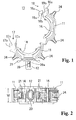
- Fig. 1 is a front view showing a state wherein a clamp 10 according to the embodiment of the present invention is open.
- Fig. 2 is a bottom view showing the state wherein the clamp 10 is open.
- Fig. 3 is a side view showing the state wherein the clamp 10 is open.
- Fig. 4 is a front view showing a state wherein the clamp 10 is closed.
- Fig. 5 is a perspective view showing the state wherein the clamp 10 is open.
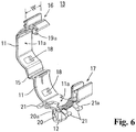
- Fig. 6 is an expanded perspective view of a clamp main body 13.
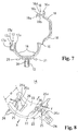
- Fig. 7 is a cross-sectional view of the clamp main body 13.
- the clamp 10 is structured by the clamp main body 13 including two concave members 11 which form a cylindrical body by combining together; a fixing device 12 provided in one concave member 11 for fixing the clamp 10 to an attachment object such as, for example, a vehicle and the like; and approximately arc-like buffer members 14 respectively disposed detachably on inner circumferential sides 11a of the concave members 11.
- the clamp main body 13 comprises two pieces of the concave members 11 whose one end is connected by a hinge 15, and engaging devices 16 and 17 provided on the other end of the respective concave members 11.
- hard resin is formed in a thin-walled and curved-surface shape, and is structured so as to increase a flexibility.
- the concave members 11 are formed by hard synthetic resin such as, for example, polyacetal resin (POM), polyamide resin (PA), and the like, and there is formed a pair of attachment holes 18 passing through for attaching the buffer members 14.
- the attachment holes 18 are provided in the center of a width size W of the concave members 11. In a portion clamped by a pair of attachment holes 18 in the respective inner circumferential sides 11a of the two concave members 11, there is provided an approximately flat planar portion.
- the engaging device 16 is provided in an end portion on a side opposite to the hinge 15 in one of the two concave members 11, and includes a base end portion 16a, and an engaging piece 16b which is provided to stand from the base end portion, and can elastically deform.
- a top portion of the engaging piece 16b there is formed an engaging projection 16c whose cross-sectional surface has an approximately triangular shape.
- the base end portion 16a and the engaging piece 16b are formed to be approximately equal to the width size W of the concave members 11.
- the lateral misalignment preventing projections 19a and 19b abut against an end portion of a guide piece 17a of the engaging device 17 provided in the end portion of the other concave member 11 so as to prevent a portion engaged by the engaging devices 16 and 17 in the two concave members 11 from being misaligned in a lateral direction (the width direction) .
- the engaging device 17 is provided in the end portion on the side opposite to the hinge 15 in the other of the two concave members 11, and includes the guide piece 17a and an elastically deformable engaging piece 17b which are provided to project approximately in a parallel manner with a predetermined interval.
- an engaging projection 17c whose cross-sectional surface has the approximately triangular shape.
- the fixing device 12 is attached to one of the two concave members 11.
- the fixing device 12 has a cylinder body whose cross-sectional surface has an oval shape, and engaging pieces 20 are formed on both ends in the width direction by cutting and rising. Also, the engaging pieces 20 can elastically deform, and include engaging step portions 20a on an outside, and one portion protrudes from an outer circumferential surface of the cylinder body of the fixing device 12.
- a plurality of abutting pieces 21 is provided to stand from a circumference of the fixing device 12 in the concave member 11 wherein the fixing device 12 is attached.
- the abutting pieces 21 are provided to obliquely extend from an outer circumference of a flat portion clamped by a pair of the attachment holes 18 of the concave members 11, and ends of the abutting pieces 21 include columnar portions 21a. Therefore, even if an abutting angle of the abutting pieces 21 changes, the abutting pieces 21 always abut against the attachment object of the clamp 10 on one portion of a circle.
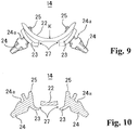
- Fig. 8 is an expanded perspective view of the buffer members 14. Also, Fig. 9 is a front view of the buffer members 14. Also, Fig. 10 is a vertical cross-sectional view of the buffer members 14.
- the buffer members 14 are formed by soft synthetic resin such as, for example, thermoplastic elastomer (TPE), olefinic elastomer (TPO), and the like, and are formed in an approximately arc shape as a whole.
- the buffer members 14 are provided to respectively correspond to the two concave members 11, and are disposed on the inner circumferential sides 11a of the respective concave members 11 detachably from the concave members 11.
- the buffer members 14 include attaching-and-detaching projections 24 formed to protrude outwardly from outside bottom portions of the leg portions 23.
- the buffer members 14 include a pair of projections 25 provided to extend toward the sides opposite to the concave members 11 from inner bottom surfaces of the leg portions 23 toward inner circumferential sides of the holding surfaces 22.
- the projections 25 are formed to protrude from imaginary inner circumferential surfaces (a surface shown by assigning a symbol "K" in Fig. 9 ) of the approximately concave-like holding surfaces 22. Therefore, when a long body such as a pipe and the like is held by the clamp 10, the projections 25 and the holding surfaces 22 of the buffer members 14 abut against the long body with two phases so as to be capable of reliably holding the long bodies with various diameters.
- ends of the projections 25 are formed such that both ends 25a are formed in an arc shape, and also that central portions 25b are flatly formed lower than both ends 25a. Also, in the holding surfaces 22 of the buffer members 14, there are provided openings, and the projections 25 are provided to extend from bottom portions inside depressed portions 26 depressed on sides of the concave members 11 from the openings.
- the buffer members 14 contact with the concave members 11 of the clamp main body 13 through the leg portions 23 formed in the center in a width H direction, so that the buffer members 14 can deform corresponding to not only a deflection in a radial direction of the long body such as the pipe and the like, but also deflections in an arrow X direction and an arrow Y direction shown in Fig. 8 .
- the buffer members 14 attached to the respective two concave members 11 are respectively formed in the same shape.
- the depressed portions 26 formed in the buffer members 14 include notches 27 between the depressed portions 26 and the holding surfaces 22 so as to make it harder to mutually contact the buffer members 14 and the projections 25 when the buffer members 14 and the projections 25 deflect.
- the attaching-and-detaching projections 24 are formed in an approximately wedge shape as a whole, and include engaging step portions 24a in a predetermined position from outside bottom surfaces of the leg portions 23. Also, the attaching-and-detaching projections 24 have a size which can be easily gripped by one's fingers at an assembly time.
- the clamp main body 13 is molded by hard resin, and the buffer members 14 are molded by soft resin with separate molds, respectively.
- the buffer members 14 are attached to the concave members 11 of the clamp main body 13.
- the attaching-and-detaching projections 24 of the buffer members 14 are inserted to pass through the attachment holes 18 formed in the concave members 11.
- the attaching-and-detaching projections 24 molded by the soft resin easily deform, and are pulled out of the attachment holes 18, and the engaging step portions 24a are engaged with and fixed to outer circumferential walls of the concave members 11.
- the attaching-and-detaching projections 24 have the size which can be easily gripped by one's fingers, so that an assembly operation of the buffer members 14 into the concave members 11 is easy.
- Two pieces of the buffer members 14 are used relative to one piece of the clamp main body 13, and also regarding the buffer members 14, the same shape can be used so as to be capable of reducing the number of components.
- the fixing device 12 of the clamp 10 is directly attached by insertion to an attachment hole formed in the vehicle and not shown in the figures.
- the fixing device 12 is attached by insertion to the attachment hole, after the engaging pieces 20 elastically deform and move backward once, the engaging pieces 20 move forward again, and the engaging step portions 20a engage with a thickness portion of the vehicle, so that the clamp 10 is fixed to the vehicle.
- the columnar portions 21a of the ends of the abutting pieces 21 formed around the fixing device 12 abut against a wall surface of the vehicle, so that the abutting pieces 21 can hold a posture of the clamp 10. Namely, since the abutting pieces 21 elastically deform, even in a case where the pipe and the like which has been held vibrates, a holding state of the clamp 10 itself cannot become unstable.
- the pipe and the like are placed on the holding surfaces 22 of the opened buffer members 14, and then the concave members 11 are closed so as to lock the engaging devices 16 and 17.
- the engaging projection 16c of the engaging device 16 is inserted between the engaging projection 17c and the guide piece 17a of the engaging device 17 so as to engage with the engaging projection 17c.
- two pieces of the concave members 11 and 11 are combined and structure the cylindrical body, and also the holding surfaces 22 of the buffer members 14 are oppositely disposed so as to hold the pipe as well.
- the projections 25 and the holding surfaces 22 respectively abut against a pipe surface independently, to thereby increase an acceptable range of a pipe diameter to be held.
- the clamp 10 can correspond to the various pipe diameters.
- the clamp 10 in a case wherein the fixed pipe vibrates due to a vibration of the automobile and the like, since the pipe is held by four pieces of the elastically deformable projections 25 and two pieces of the buffer members 14, the generated vibration can be effectively attenuated. Also, since the projections 25 are provided to extend from the inner bottom surfaces of the depressed portions of the leg portions 23 formed to bulge out, at a time of deformation, it is difficult to be affected by the deformation of the buffer members 14. Therefore, based on an elastic coefficient in which the projections 25 and the buffer members 14 differ, the projections 25 can correspond to a different vibration property.
- the buffer members 14 molded by the soft resin are attached by insertion to the concave members (the clamp main body 13) through the leg portions 23 so as to be capable of increasing a deformation range, and of improving an attenuation performance.
- the leg portions 23 are provided in the center in the width H direction of the buffer members 14, so that the buffer members 14 allow the pipe held by the buffer members 14 to move in a pitching direction or a yawing direction. Therefore, the acceptable range wherein the tube body such as the long pipe, the tube, and the like holds, expands.
- a soft material can exert the flexibility more by bending than by compressing so as to be capable of improving the acceptable range of a tube diameter by using a bending deformation, and also a vibration suppression effect improves.
- both ends 25a are formed in the arc shape, and also the central portions 25b are flatly formed lower than both ends 25a so as to increase an abutting property against the pipe and the like.
- the clamp 10 is formed by the clamp main body 13 which forms the cylindrical body by combining the concave members 11, and also comprises the fixing device for fixing the clamp to any of the concave members 11; and the approximately arc-like buffer members 14 disposed on the inner circumferential sides of the concave members 11.
- the buffer members 14 include the holding surfaces 22 structured in an approximately concave shape, and are provided with the leg portions 23 formed to bulge out on side surfaces facing the concave members 11.
- the long body is held by the buffer members 14 disposed on an inner circumference of the concave members 11 structuring the cylindrical body, so that the buffer members 14 can reliably hold even the long body with a different diameter, and there is no possibility that the long body will drop.
- the buffer members 14 include the attaching-and-detaching projections 24 which can protrude from the attachment holes 18 formed in the concave members 11. Also, the attaching-and-detaching projections 24 are formed to protrude from the outside bottom portions of the leg portions 23 formed to bulge out, so that when the clamp main body 13 and the buffer members 14 are assembled, an assembly process is facilitated, and also a vibration suppression performance can be improved.
- the buffer members comprise a pair of projections provided to extend from the leg portions 23 and the projections are formed to protrude from the imaginary inner circumferential surfaces of the holding surfaces 22, so that the projections of the buffer members 14 and the holding surfaces 22 abut against the long body such as the pipe and the like with two phases so as to be capable of corresponding to a plurality of tube diameters.
- the buffer members 14 contact with the concave members 11 of the clamp main body 13 through the leg portions 23 formed in the center in the width direction so as to be capable of corresponding to not only the vibration in the radial direction of the long body such as the pipe and the like, but also the vibration in the pitching or the yawing direction.
- a plurality of buffer members 14, which are respectively formed in the same shape, are provided so as to be capable of reducing the number of the components.
- the leg portions 23 formed to bulge out include open depressed portions in the holding surfaces 22 on the inner circumferential sides, and the projections are provided to stand from the bottom surfaces of the depressed portions so as to be capable of making the deformation of the projections smooth, and of corresponding to a change of the tube diameter.
- the long body which the clamp 10 according to the present embodiment can hold is not limited to pipes, and the clamp 10 can easily hold tubular bodies such as tubes and the like, or rod-like members such as a rod, a wire, and the like.
- the buffer members 14 can correspond to various unique vibrations.
- a case of comprising two concave members 11 structuring the clamp main body 13 has been explained; however, the concave members 11 may be provided with three or above.
Landscapes
- Engineering & Computer Science (AREA)
- General Engineering & Computer Science (AREA)
- Mechanical Engineering (AREA)
- Supports For Pipes And Cables (AREA)
- Clamps And Clips (AREA)
- Insertion Pins And Rivets (AREA)
- Installation Of Indoor Wiring (AREA)
Claims (5)
- Attache (10) pour maintenir des corps tubulaires allongés comprenant :un corps principal d'attache (13) comportant une pluralité d'éléments concaves (11) formant un corps cylindrique en les combinant, et un dispositif de fixation (12) prévu dans une quelconque pluralité d'éléments concaves (11) pour la fixation de l'attache (10) à un objet de fixation ; etun élément tampon (14) approximativement en forme d'arc disposé sur un côté circonférentiel interne de chaque élément concave (11),en ce que sur la surface latérale de chaque élément tampon (14) face à l'élément concave (11), une paire de parties de pattes (23) est formée pour faire saillie, et sur la surface latérale opposée de chaque élément tampon (14), une surface de maintien (22) approximativement de forme concave est ménagée,caractérisée en ce que
chaque élément tampon (14) comporte une paire de parties saillantes (25) ménagée pour s'étendre vers les côtés opposés aux éléments concaves (11) à partir des surfaces inférieures internes des parties de pattes (23) vers des côtés circonférentiels internes des surfaces de maintien (22), en ce que les parties saillantes (25) sont formées de manière à dépasser des surfaces circonférentielles internes imaginaires (K) des surfaces de maintien (22) approximativement de forme concave, en ce que, utilisées, les parties saillantes (25) et les surfaces de maintien (22) de chaque élément tampon (14) viennent en butée indépendamment l'une de l'autre contre le corps tubulaire allongé à maintenir de manière à pouvoir maintenir en toute sécurité des corps tubulaires allongés présentant des diamètres différents. - Attache (10) selon la revendication 1, en ce que chaque élément tampon (14) comporte une partie saillante d'accrochage et de décrochage (24) formée pour faire saillie à partir d'une partie inférieure externe de chaque partie de patte (23), et en insérant chaque partie saillante d'accrochage et de décrochage (24) pour traverser un trou de fixation (18) formé dans l'élément concave (11) à partir du côté circonférentiel interne de l'élément concave (11), chaque élément tampon (14) est fixé à l'élément concave (11).
- Attache (10) selon la revendication 1 ou 2, en ce que chaque élément tampon (14) entre en contact avec l'élément concave (11) du corps principal d'attache (13) par la partie de patte (23) formée au centre dans un sens de la largeur (H).
- Attache (10) selon l'une des revendications 1 à 3, en ce que chaque élément tampon (14) est formé de manière à avoir la même forme.
- Attache (10) selon l'une des revendications 1 à 4, en ce qu'une parie d'ouvertures est ménagée dans la surface de maintien (22) de chaque élément tampon (14), et une partie inférieure d'une partie enfoncée (26) enfoncée vers l'élément concave (11) à partir de chaque ouverture forme la surface inférieure interne de chaque partie de patte (23) à partir de laquelle chaque partie saillante (25) s'étend.
Applications Claiming Priority (2)
| Application Number | Priority Date | Filing Date | Title |
|---|---|---|---|
| JP2010015265A JP5360498B2 (ja) | 2010-01-27 | 2010-01-27 | クランプ |
| PCT/JP2011/051401 WO2011093299A1 (fr) | 2010-01-27 | 2011-01-26 | Fixation |
Publications (3)
| Publication Number | Publication Date |
|---|---|
| EP2530335A1 EP2530335A1 (fr) | 2012-12-05 |
| EP2530335A4 EP2530335A4 (fr) | 2017-07-12 |
| EP2530335B1 true EP2530335B1 (fr) | 2019-03-06 |
Family
ID=44319286
Family Applications (1)
| Application Number | Title | Priority Date | Filing Date |
|---|---|---|---|
| EP11737012.2A Active EP2530335B1 (fr) | 2010-01-27 | 2011-01-26 | Fixation |
Country Status (5)
| Country | Link |
|---|---|
| US (1) | US8827214B2 (fr) |
| EP (1) | EP2530335B1 (fr) |
| JP (1) | JP5360498B2 (fr) |
| CN (1) | CN102770670B (fr) |
| WO (1) | WO2011093299A1 (fr) |
Families Citing this family (65)
| Publication number | Priority date | Publication date | Assignee | Title |
|---|---|---|---|---|
| JP5701888B2 (ja) | 2010-09-07 | 2015-04-15 | パナソニック インテレクチュアル プロパティ コーポレーション オブアメリカPanasonic Intellectual Property Corporation of America | 基地局装置、通信方法、及び集積回路 |
| JP5821048B2 (ja) * | 2011-03-18 | 2015-11-24 | 株式会社ニックス | クランプ具 |
| JP5772444B2 (ja) * | 2011-09-22 | 2015-09-02 | 住友電装株式会社 | クランプ |
| WO2013051090A1 (fr) * | 2011-10-03 | 2013-04-11 | トヨタ車体 株式会社 | Élément de fixation |
| KR101338731B1 (ko) * | 2011-11-22 | 2013-12-06 | 한국가스공사 | 파이프 댐핑 장치 |
| CA2862409C (fr) | 2012-02-02 | 2019-04-09 | Bombardier Inc. | Dispositif de retenue de cable et procede de retenue de cable dans un avion |
| DE102012004693B4 (de) * | 2012-03-12 | 2020-07-16 | Murrplastik Systemtechnik Gmbh | Systemhalter |
| US8967556B2 (en) * | 2012-03-13 | 2015-03-03 | Newfrey Llc | Two shot tube retention clip with resilient living hinge |
| FR2988230B1 (fr) * | 2012-03-19 | 2018-10-26 | Airbus Operations | Bague de segregation de torons |
| JP5871684B2 (ja) * | 2012-03-27 | 2016-03-01 | ダイハツ工業株式会社 | クランプ |
| JP5798989B2 (ja) * | 2012-08-10 | 2015-10-21 | 株式会社ニフコ | 保持具 |
| CN103206621B (zh) * | 2013-03-21 | 2015-11-25 | 宁波腾隆户外用品有限公司 | 头灯 |
| WO2014146600A1 (fr) * | 2013-03-21 | 2014-09-25 | 宁波腾隆户外用品有限公司 | Lampe frontale |
| US10578234B2 (en) | 2013-05-02 | 2020-03-03 | Victaulic Company | Coupling having arcuate stiffness ribs |
| US20150084336A1 (en) * | 2013-09-24 | 2015-03-26 | Alan Gregory BROWN | Corrugated pipe coupling and repair apparatus |
| ITVI20130248A1 (it) * | 2013-10-10 | 2015-04-11 | Ritmo Spa | Morsa perfezionata per il bloccaggio di tubazioni e/o corpi cilindrici in genere. |
| US10605295B2 (en) * | 2014-01-15 | 2020-03-31 | Tlv Co., Ltd. | Sensor fixation device |
| JP6164530B2 (ja) * | 2014-05-15 | 2017-07-19 | 住友電装株式会社 | パイプ用クリップ |
| US10125906B2 (en) * | 2014-08-21 | 2018-11-13 | Nordson Corporation | Reusable clamp with latch release arm for connecting conduit sections and associated methods |
| JP6435081B2 (ja) * | 2014-10-25 | 2018-12-05 | 未来工業株式会社 | 配線・配管材の保持部の構造及び保持具 |
| GB2535437A (en) * | 2014-12-19 | 2016-08-24 | Avon Automotive Uk Holdings Ltd | Pipe clip |
| US20190267785A1 (en) | 2015-08-24 | 2019-08-29 | Sticnstac, LLC | Releasable holder for cables and conduit |
| US12113344B2 (en) * | 2015-08-24 | 2024-10-08 | Sticnstac Llc | Releasable holder for cables and conduit |
| US20170063064A1 (en) | 2015-08-24 | 2017-03-02 | William Gary Gintz | Releasable holder for cables and conduit |
| JP6229699B2 (ja) * | 2015-08-31 | 2017-11-15 | 住友電装株式会社 | シールド導電路 |
| CN105370677A (zh) * | 2015-11-30 | 2016-03-02 | 奇瑞商用车(安徽)有限公司 | 一种汽车内饰护板卡扣座及其和卡扣的安装方法 |
| SG11201803931WA (en) | 2015-12-28 | 2018-06-28 | Victaulic Co Of America | Adapter coupling |
| US10903632B2 (en) | 2016-02-05 | 2021-01-26 | Hellermanntyton Corporation | Adjustable P-clamp with multiple mounting options |
| US10119631B2 (en) * | 2016-02-05 | 2018-11-06 | Hellermanntyton Corporation | Adjustable p-clamp |
| USD829090S1 (en) * | 2016-04-06 | 2018-09-25 | Hellermanntyton Corporation | Adjustable P clamp |
| USD784799S1 (en) * | 2016-04-06 | 2017-04-25 | Hellermann Tyton Corporation | Adjustable P-clamp |
| CN109154408B (zh) * | 2016-04-13 | 2020-09-08 | Abb有限公司 | 管道夹和具有管道夹和管道的管道夹组件 |
| US10605394B2 (en) | 2016-05-16 | 2020-03-31 | Victaulic Company | Fitting having tabbed retainer and observation apertures |
| US10533688B2 (en) | 2016-05-16 | 2020-01-14 | Victaulic Company | Coupling having tabbed retainer |
| US10859190B2 (en) | 2016-05-16 | 2020-12-08 | Victaulic Company | Sprung coupling |
| CN105909432A (zh) * | 2016-07-01 | 2016-08-31 | 青岛雷沃挖掘机有限公司 | 一种空气滤清器安装装置 |
| JP6684675B2 (ja) * | 2016-07-25 | 2020-04-22 | 大和化成工業株式会社 | 組付け型車両部品 |
| CN106704436A (zh) * | 2017-02-14 | 2017-05-24 | 孟书芳 | 一种电缆用夹紧装置 |
| CN107289199A (zh) * | 2017-08-23 | 2017-10-24 | 重庆松芝汽车空调有限公司 | 汽车空调系统用管路固定管夹 |
| JP6841204B2 (ja) | 2017-10-13 | 2021-03-10 | トヨタ自動車株式会社 | エンジンの冷却構造 |
| CN107588241A (zh) * | 2017-10-20 | 2018-01-16 | 成都科盛石油科技有限公司 | 能够提高稳定性的石油管道支撑装置 |
| DE202018106037U1 (de) | 2018-10-22 | 2018-11-05 | Igus Gmbh | Rinnenclip für Führungsrinnen von Energieführungsketten |
| JP7132083B2 (ja) | 2018-10-25 | 2022-09-06 | 株式会社デンソー | クランプ |
| US10704710B2 (en) * | 2018-11-20 | 2020-07-07 | The Boeing Company | Easy lock P-clamp |
| JP7205270B2 (ja) * | 2019-02-08 | 2023-01-17 | 株式会社オートネットワーク技術研究所 | 電磁シールド部材及びワイヤハーネス |
| JP7287827B2 (ja) * | 2019-04-25 | 2023-06-06 | 日栄インテック株式会社 | 配管支持具 |
| CN110143176B (zh) * | 2019-07-01 | 2021-09-28 | 安徽江淮汽车集团股份有限公司 | 一种汽车多功能线夹 |
| CN110143177B (zh) * | 2019-07-01 | 2023-01-24 | 安徽江淮汽车集团股份有限公司 | 汽车多功能线夹 |
| US11781683B2 (en) | 2019-11-15 | 2023-10-10 | Victaulic Company | Shrouded coupling |
| EP3925833B1 (fr) * | 2020-06-19 | 2024-02-14 | Illinois Tool Works INC. | Clip de fixation |
| CN112090617A (zh) * | 2020-09-25 | 2020-12-18 | 合肥市东庐机械制造有限公司 | 一种叉车配件喷涂加工设备 |
| CN112165057B (zh) * | 2020-09-30 | 2022-05-20 | 安徽江淮汽车集团股份有限公司 | 车用卡线夹结构 |
| CN112636018A (zh) * | 2020-11-19 | 2021-04-09 | 国网山东省电力公司惠民县供电公司 | 一种接地线夹及其使用方法 |
| IT202100031073A1 (it) * | 2021-12-10 | 2023-06-10 | Ritmo Spa | Morsa, particolarmente per apparecchiature per la saldatura di tubazioni |
| KR102669614B1 (ko) * | 2021-12-14 | 2024-05-27 | (주) 명보 | 클립형 와이어 홀더 |
| US12140254B2 (en) | 2022-01-06 | 2024-11-12 | Illinois Tool Works Inc. | Adaptive retainer |
| FR3131760A1 (fr) * | 2022-01-11 | 2023-07-14 | Illinois Tool Works Inc. | Collier de serrage pour la fixation de tuyau |
| US20230295916A1 (en) * | 2022-03-18 | 2023-09-21 | Erico International Corporation | Mounting Clamp |
| US12326210B2 (en) | 2022-03-24 | 2025-06-10 | Hellermanntyton Corporation | Quick attach clamp |
| US12338848B2 (en) | 2022-06-30 | 2025-06-24 | Hellermanntyton Corporation | Anti-wobble fir tree mount |
| US12176698B2 (en) | 2022-07-18 | 2024-12-24 | Rosenberger Hochfrequenztechnik Gmbh & Co Kg | Cable holder, stack of cable holders and fixation arrangement |
| US20240360922A1 (en) | 2023-04-28 | 2024-10-31 | Hellermanntyton Corporation | Cable Tie Cradle Mount Fixings |
| FR3153124A1 (fr) * | 2023-09-20 | 2025-03-21 | Psa Automobiles Sa | Ensemble de protection de canalisation à écarteur |
| US12372169B2 (en) * | 2023-09-22 | 2025-07-29 | Paccar Inc | Retention clamp |
| US20250164034A1 (en) * | 2023-11-20 | 2025-05-22 | Cooper-Standard Automotive Inc | Modular retention clip |
Family Cites Families (30)
| Publication number | Priority date | Publication date | Assignee | Title |
|---|---|---|---|---|
| DE1987450U (de) * | 1968-06-12 | Gesellschaft fur technischen Fortschritt mbH 5410 Hohr-Grenzhausen | Gerauschisolierte Rohrschelle | |
| CH630160A5 (en) * | 1979-07-02 | 1982-05-28 | Samvaz Sa | Universal fastening collar for pipes and ducts |
| DE4039822C1 (fr) * | 1990-12-13 | 1992-07-23 | A. Raymond Kg, 7850 Loerrach, De | |
| FR2683884A1 (fr) * | 1991-11-20 | 1993-05-21 | Caillau Ets | Collier de fixation. |
| DE9205682U1 (de) * | 1992-04-28 | 1992-06-25 | Sikla GmbH & Co KG, 7201 Hausen | Rohrschelle |
| GB2288205B (en) * | 1994-04-05 | 1998-04-22 | Crp Marine Ltd | Buoyancy module provided with clamp |
| JPH08145241A (ja) * | 1994-11-21 | 1996-06-07 | Toyota Auto Body Co Ltd | ワイヤハーネス用クランプ |
| US5620210A (en) * | 1995-10-24 | 1997-04-15 | Stanley Aviation Corporation | Fluid conduit coupling |
| JP3475319B2 (ja) * | 1997-06-30 | 2003-12-08 | 株式会社パイオラックス | 防振クランプ |
| US6164604A (en) * | 1998-02-03 | 2000-12-26 | Oatey Co. | Pipe clamps |
| JP2000002364A (ja) * | 1998-06-18 | 2000-01-07 | Furukawa Electric Co Ltd:The | クランプ |
| JP2001099357A (ja) | 1999-09-28 | 2001-04-10 | Piolax Inc | パイプクリップ |
| US6908123B2 (en) * | 2000-10-27 | 2005-06-21 | Fluidmaster, Inc. | Bayonet quick coupler |
| JP3741998B2 (ja) * | 2001-11-14 | 2006-02-01 | 矢崎総業株式会社 | コルゲートチューブ用回転保持具 |
| CN1475689A (zh) * | 2002-08-12 | 2004-02-18 | 艾姆哈特有限公司 | 用于管路等的紧固件 |
| US6913294B2 (en) * | 2002-11-14 | 2005-07-05 | Halla Climate Control Canada, Inc. | Coupling for coaxial connection of fluid conduits |
| US7278190B2 (en) * | 2003-07-03 | 2007-10-09 | Newfrey Llc | Two component fuel and brake line clip |
| US20050098688A1 (en) | 2003-11-10 | 2005-05-12 | Itt Manufacturing Enterprises, Inc. | Multi-material isolator bundle clip |
| US7175138B2 (en) * | 2004-05-10 | 2007-02-13 | Andrew Corporation | Stackable cable hanger |
| JP2007232063A (ja) | 2006-02-28 | 2007-09-13 | Nippon Pop Rivets & Fasteners Ltd | パイプ等の防振保持具 |
| DE202006006347U1 (de) * | 2006-04-19 | 2006-06-14 | Veritas Ag | Halteeinrichtung für mindestens eine Leitung |
| GB0706534D0 (en) * | 2007-04-04 | 2007-05-09 | Balmoral Group | Installation tool |
| JP5045584B2 (ja) | 2008-07-01 | 2012-10-10 | 株式会社デンソー | プログラム書き換え装置 |
| JP2010133543A (ja) * | 2008-12-08 | 2010-06-17 | Nippon Pop Rivets & Fasteners Ltd | コルゲートチューブのクランプ |
| US8439317B2 (en) * | 2009-02-27 | 2013-05-14 | Franklin Fastener Company | Grommeted clamp assembly |
| US7887012B2 (en) * | 2009-03-31 | 2011-02-15 | Denso International America, Inc. | Insert for tube retaining bracket |
| JP5694703B2 (ja) * | 2009-11-27 | 2015-04-01 | 株式会社ニフコ | クランプ |
| CN103249980B (zh) * | 2010-10-15 | 2015-11-25 | 株式会社利富高 | 夹具 |
| US8366059B2 (en) * | 2011-01-06 | 2013-02-05 | GM Global Technology Operations LLC | Position controlled cable guide clip |
| US20120318935A1 (en) * | 2011-06-16 | 2012-12-20 | Benedetti Steven M | Multiple tube diameter retaining insert |
-
2010
- 2010-01-27 JP JP2010015265A patent/JP5360498B2/ja active Active
-
2011
- 2011-01-26 WO PCT/JP2011/051401 patent/WO2011093299A1/fr not_active Ceased
- 2011-01-26 CN CN201180007255.5A patent/CN102770670B/zh active Active
- 2011-01-26 US US13/574,507 patent/US8827214B2/en active Active
- 2011-01-26 EP EP11737012.2A patent/EP2530335B1/fr active Active
Non-Patent Citations (1)
| Title |
|---|
| None * |
Also Published As
| Publication number | Publication date |
|---|---|
| CN102770670B (zh) | 2015-04-01 |
| JP2011153663A (ja) | 2011-08-11 |
| EP2530335A4 (fr) | 2017-07-12 |
| WO2011093299A1 (fr) | 2011-08-04 |
| JP5360498B2 (ja) | 2013-12-04 |
| US8827214B2 (en) | 2014-09-09 |
| EP2530335A1 (fr) | 2012-12-05 |
| CN102770670A (zh) | 2012-11-07 |
| US20130001373A1 (en) | 2013-01-03 |
Similar Documents
| Publication | Publication Date | Title |
|---|---|---|
| EP2530335B1 (fr) | Fixation | |
| US7011277B2 (en) | Antivibration clamp for elongated objects | |
| JP5753169B2 (ja) | 導電性フローティング式パイプ組付クリップ | |
| JP5891961B2 (ja) | グロメット及びグロメット付ワイヤーハーネス | |
| JP6770924B2 (ja) | グロメット | |
| EP1529997B1 (fr) | Support isolant de conduit fabriqué en plusieurs matériaux | |
| JP6399383B2 (ja) | 防振クランプ | |
| JP2010190423A (ja) | 導電性及び隔離型の2ショット・チューブ・クランプ | |
| WO2017135339A1 (fr) | Ensemble collier de serrage et bride de fixation et structure de montage | |
| JP2003106479A (ja) | 管体支持クランプ | |
| JP2008190682A (ja) | 防振クランプ装置 | |
| JP4068331B2 (ja) | クランプ | |
| JP4974531B2 (ja) | 線条体の保持具 | |
| JP2013247760A (ja) | ワイヤハーネス用のクランプ | |
| JP5796541B2 (ja) | ワイヤーハーネス固定具 | |
| JP2008082387A (ja) | クランプ | |
| JP2013053657A (ja) | コネクタ用プラグ | |
| JP6298707B2 (ja) | 取付具 | |
| JP2019086085A (ja) | ホースクランプ | |
| JP7770152B2 (ja) | 長尺部材の保持具 | |
| JP6741508B2 (ja) | コントロールケーブル | |
| JP5397091B2 (ja) | クランプ | |
| EP2348225B1 (fr) | Amortisseur anti-vibration pour ressort hélicoïdal | |
| KR101964815B1 (ko) | 와이어링 하네스 고정 클립 | |
| JP2025087036A (ja) | 外装部材及びワイヤハーネス |
Legal Events
| Date | Code | Title | Description |
|---|---|---|---|
| PUAI | Public reference made under article 153(3) epc to a published international application that has entered the european phase |
Free format text: ORIGINAL CODE: 0009012 |
|
| 17P | Request for examination filed |
Effective date: 20120726 |
|
| AK | Designated contracting states |
Kind code of ref document: A1 Designated state(s): AL AT BE BG CH CY CZ DE DK EE ES FI FR GB GR HR HU IE IS IT LI LT LU LV MC MK MT NL NO PL PT RO RS SE SI SK SM TR |
|
| DAX | Request for extension of the european patent (deleted) | ||
| RA4 | Supplementary search report drawn up and despatched (corrected) |
Effective date: 20170612 |
|
| RIC1 | Information provided on ipc code assigned before grant |
Ipc: B60R 16/02 20060101ALI20170606BHEP Ipc: H02G 3/30 20060101ALI20170606BHEP Ipc: F16L 55/035 20060101ALI20170606BHEP Ipc: F16L 3/16 20060101ALI20170606BHEP Ipc: F16L 3/10 20060101ALI20170606BHEP Ipc: F16B 21/08 20060101ALI20170606BHEP Ipc: F16B 2/10 20060101AFI20170606BHEP Ipc: F16L 3/12 20060101ALI20170606BHEP |
|
| RIC1 | Information provided on ipc code assigned before grant |
Ipc: H02G 3/30 20060101ALI20180803BHEP Ipc: F16B 21/08 20060101ALI20180803BHEP Ipc: F16L 3/12 20060101ALI20180803BHEP Ipc: F16L 3/10 20060101ALI20180803BHEP Ipc: F16L 3/16 20060101ALI20180803BHEP Ipc: F16L 55/035 20060101ALI20180803BHEP Ipc: B60R 16/02 20060101ALI20180803BHEP Ipc: F16B 2/10 20060101AFI20180803BHEP |
|
| GRAP | Despatch of communication of intention to grant a patent |
Free format text: ORIGINAL CODE: EPIDOSNIGR1 |
|
| STAA | Information on the status of an ep patent application or granted ep patent |
Free format text: STATUS: GRANT OF PATENT IS INTENDED |
|
| INTG | Intention to grant announced |
Effective date: 20180919 |
|
| GRAS | Grant fee paid |
Free format text: ORIGINAL CODE: EPIDOSNIGR3 |
|
| RIN1 | Information on inventor provided before grant (corrected) |
Inventor name: OGAWA TAKAYA |
|
| RAP1 | Party data changed (applicant data changed or rights of an application transferred) |
Owner name: NIFCO INC. |
|
| RAP1 | Party data changed (applicant data changed or rights of an application transferred) |
Owner name: NIFCO INC. |
|
| GRAA | (expected) grant |
Free format text: ORIGINAL CODE: 0009210 |
|
| STAA | Information on the status of an ep patent application or granted ep patent |
Free format text: STATUS: THE PATENT HAS BEEN GRANTED |
|
| RAP1 | Party data changed (applicant data changed or rights of an application transferred) |
Owner name: NIFCO INC. |
|
| AK | Designated contracting states |
Kind code of ref document: B1 Designated state(s): AL AT BE BG CH CY CZ DE DK EE ES FI FR GB GR HR HU IE IS IT LI LT LU LV MC MK MT NL NO PL PT RO RS SE SI SK SM TR |
|
| REG | Reference to a national code |
Ref country code: GB Ref legal event code: FG4D |
|
| REG | Reference to a national code |
Ref country code: AT Ref legal event code: REF Ref document number: 1104944 Country of ref document: AT Kind code of ref document: T Effective date: 20190315 Ref country code: CH Ref legal event code: EP |
|
| REG | Reference to a national code |
Ref country code: DE Ref legal event code: R096 Ref document number: 602011056875 Country of ref document: DE |
|
| REG | Reference to a national code |
Ref country code: IE Ref legal event code: FG4D |
|
| REG | Reference to a national code |
Ref country code: NL Ref legal event code: MP Effective date: 20190306 |
|
| REG | Reference to a national code |
Ref country code: LT Ref legal event code: MG4D |
|
| PG25 | Lapsed in a contracting state [announced via postgrant information from national office to epo] |
Ref country code: FI Free format text: LAPSE BECAUSE OF FAILURE TO SUBMIT A TRANSLATION OF THE DESCRIPTION OR TO PAY THE FEE WITHIN THE PRESCRIBED TIME-LIMIT Effective date: 20190306 Ref country code: LT Free format text: LAPSE BECAUSE OF FAILURE TO SUBMIT A TRANSLATION OF THE DESCRIPTION OR TO PAY THE FEE WITHIN THE PRESCRIBED TIME-LIMIT Effective date: 20190306 Ref country code: SE Free format text: LAPSE BECAUSE OF FAILURE TO SUBMIT A TRANSLATION OF THE DESCRIPTION OR TO PAY THE FEE WITHIN THE PRESCRIBED TIME-LIMIT Effective date: 20190306 Ref country code: NO Free format text: LAPSE BECAUSE OF FAILURE TO SUBMIT A TRANSLATION OF THE DESCRIPTION OR TO PAY THE FEE WITHIN THE PRESCRIBED TIME-LIMIT Effective date: 20190606 |
|
| PG25 | Lapsed in a contracting state [announced via postgrant information from national office to epo] |
Ref country code: GR Free format text: LAPSE BECAUSE OF FAILURE TO SUBMIT A TRANSLATION OF THE DESCRIPTION OR TO PAY THE FEE WITHIN THE PRESCRIBED TIME-LIMIT Effective date: 20190607 Ref country code: LV Free format text: LAPSE BECAUSE OF FAILURE TO SUBMIT A TRANSLATION OF THE DESCRIPTION OR TO PAY THE FEE WITHIN THE PRESCRIBED TIME-LIMIT Effective date: 20190306 Ref country code: NL Free format text: LAPSE BECAUSE OF FAILURE TO SUBMIT A TRANSLATION OF THE DESCRIPTION OR TO PAY THE FEE WITHIN THE PRESCRIBED TIME-LIMIT Effective date: 20190306 Ref country code: BG Free format text: LAPSE BECAUSE OF FAILURE TO SUBMIT A TRANSLATION OF THE DESCRIPTION OR TO PAY THE FEE WITHIN THE PRESCRIBED TIME-LIMIT Effective date: 20190606 Ref country code: RS Free format text: LAPSE BECAUSE OF FAILURE TO SUBMIT A TRANSLATION OF THE DESCRIPTION OR TO PAY THE FEE WITHIN THE PRESCRIBED TIME-LIMIT Effective date: 20190306 Ref country code: HR Free format text: LAPSE BECAUSE OF FAILURE TO SUBMIT A TRANSLATION OF THE DESCRIPTION OR TO PAY THE FEE WITHIN THE PRESCRIBED TIME-LIMIT Effective date: 20190306 |
|
| REG | Reference to a national code |
Ref country code: AT Ref legal event code: MK05 Ref document number: 1104944 Country of ref document: AT Kind code of ref document: T Effective date: 20190306 |
|
| PG25 | Lapsed in a contracting state [announced via postgrant information from national office to epo] |
Ref country code: ES Free format text: LAPSE BECAUSE OF FAILURE TO SUBMIT A TRANSLATION OF THE DESCRIPTION OR TO PAY THE FEE WITHIN THE PRESCRIBED TIME-LIMIT Effective date: 20190306 Ref country code: RO Free format text: LAPSE BECAUSE OF FAILURE TO SUBMIT A TRANSLATION OF THE DESCRIPTION OR TO PAY THE FEE WITHIN THE PRESCRIBED TIME-LIMIT Effective date: 20190306 Ref country code: CZ Free format text: LAPSE BECAUSE OF FAILURE TO SUBMIT A TRANSLATION OF THE DESCRIPTION OR TO PAY THE FEE WITHIN THE PRESCRIBED TIME-LIMIT Effective date: 20190306 Ref country code: AL Free format text: LAPSE BECAUSE OF FAILURE TO SUBMIT A TRANSLATION OF THE DESCRIPTION OR TO PAY THE FEE WITHIN THE PRESCRIBED TIME-LIMIT Effective date: 20190306 Ref country code: PT Free format text: LAPSE BECAUSE OF FAILURE TO SUBMIT A TRANSLATION OF THE DESCRIPTION OR TO PAY THE FEE WITHIN THE PRESCRIBED TIME-LIMIT Effective date: 20190706 Ref country code: IT Free format text: LAPSE BECAUSE OF FAILURE TO SUBMIT A TRANSLATION OF THE DESCRIPTION OR TO PAY THE FEE WITHIN THE PRESCRIBED TIME-LIMIT Effective date: 20190306 Ref country code: EE Free format text: LAPSE BECAUSE OF FAILURE TO SUBMIT A TRANSLATION OF THE DESCRIPTION OR TO PAY THE FEE WITHIN THE PRESCRIBED TIME-LIMIT Effective date: 20190306 Ref country code: SK Free format text: LAPSE BECAUSE OF FAILURE TO SUBMIT A TRANSLATION OF THE DESCRIPTION OR TO PAY THE FEE WITHIN THE PRESCRIBED TIME-LIMIT Effective date: 20190306 |
|
| PG25 | Lapsed in a contracting state [announced via postgrant information from national office to epo] |
Ref country code: PL Free format text: LAPSE BECAUSE OF FAILURE TO SUBMIT A TRANSLATION OF THE DESCRIPTION OR TO PAY THE FEE WITHIN THE PRESCRIBED TIME-LIMIT Effective date: 20190306 Ref country code: SM Free format text: LAPSE BECAUSE OF FAILURE TO SUBMIT A TRANSLATION OF THE DESCRIPTION OR TO PAY THE FEE WITHIN THE PRESCRIBED TIME-LIMIT Effective date: 20190306 |
|
| REG | Reference to a national code |
Ref country code: DE Ref legal event code: R097 Ref document number: 602011056875 Country of ref document: DE |
|
| PG25 | Lapsed in a contracting state [announced via postgrant information from national office to epo] |
Ref country code: IS Free format text: LAPSE BECAUSE OF FAILURE TO SUBMIT A TRANSLATION OF THE DESCRIPTION OR TO PAY THE FEE WITHIN THE PRESCRIBED TIME-LIMIT Effective date: 20190706 Ref country code: AT Free format text: LAPSE BECAUSE OF FAILURE TO SUBMIT A TRANSLATION OF THE DESCRIPTION OR TO PAY THE FEE WITHIN THE PRESCRIBED TIME-LIMIT Effective date: 20190306 |
|
| PLBE | No opposition filed within time limit |
Free format text: ORIGINAL CODE: 0009261 |
|
| STAA | Information on the status of an ep patent application or granted ep patent |
Free format text: STATUS: NO OPPOSITION FILED WITHIN TIME LIMIT |
|
| PG25 | Lapsed in a contracting state [announced via postgrant information from national office to epo] |
Ref country code: DK Free format text: LAPSE BECAUSE OF FAILURE TO SUBMIT A TRANSLATION OF THE DESCRIPTION OR TO PAY THE FEE WITHIN THE PRESCRIBED TIME-LIMIT Effective date: 20190306 |
|
| 26N | No opposition filed |
Effective date: 20191209 |
|
| PG25 | Lapsed in a contracting state [announced via postgrant information from national office to epo] |
Ref country code: SI Free format text: LAPSE BECAUSE OF FAILURE TO SUBMIT A TRANSLATION OF THE DESCRIPTION OR TO PAY THE FEE WITHIN THE PRESCRIBED TIME-LIMIT Effective date: 20190306 |
|
| PG25 | Lapsed in a contracting state [announced via postgrant information from national office to epo] |
Ref country code: TR Free format text: LAPSE BECAUSE OF FAILURE TO SUBMIT A TRANSLATION OF THE DESCRIPTION OR TO PAY THE FEE WITHIN THE PRESCRIBED TIME-LIMIT Effective date: 20190306 |
|
| PGFP | Annual fee paid to national office [announced via postgrant information from national office to epo] |
Ref country code: GB Payment date: 20200115 Year of fee payment: 10 |
|
| PG25 | Lapsed in a contracting state [announced via postgrant information from national office to epo] |
Ref country code: MC Free format text: LAPSE BECAUSE OF FAILURE TO SUBMIT A TRANSLATION OF THE DESCRIPTION OR TO PAY THE FEE WITHIN THE PRESCRIBED TIME-LIMIT Effective date: 20190306 |
|
| REG | Reference to a national code |
Ref country code: CH Ref legal event code: PL |
|
| REG | Reference to a national code |
Ref country code: BE Ref legal event code: MM Effective date: 20200131 |
|
| PG25 | Lapsed in a contracting state [announced via postgrant information from national office to epo] |
Ref country code: LU Free format text: LAPSE BECAUSE OF NON-PAYMENT OF DUE FEES Effective date: 20200126 |
|
| PG25 | Lapsed in a contracting state [announced via postgrant information from national office to epo] |
Ref country code: CH Free format text: LAPSE BECAUSE OF NON-PAYMENT OF DUE FEES Effective date: 20200131 Ref country code: LI Free format text: LAPSE BECAUSE OF NON-PAYMENT OF DUE FEES Effective date: 20200131 Ref country code: BE Free format text: LAPSE BECAUSE OF NON-PAYMENT OF DUE FEES Effective date: 20200131 |
|
| PG25 | Lapsed in a contracting state [announced via postgrant information from national office to epo] |
Ref country code: IE Free format text: LAPSE BECAUSE OF NON-PAYMENT OF DUE FEES Effective date: 20200126 |
|
| GBPC | Gb: european patent ceased through non-payment of renewal fee |
Effective date: 20210126 |
|
| PG25 | Lapsed in a contracting state [announced via postgrant information from national office to epo] |
Ref country code: GB Free format text: LAPSE BECAUSE OF NON-PAYMENT OF DUE FEES Effective date: 20210126 |
|
| PG25 | Lapsed in a contracting state [announced via postgrant information from national office to epo] |
Ref country code: MT Free format text: LAPSE BECAUSE OF FAILURE TO SUBMIT A TRANSLATION OF THE DESCRIPTION OR TO PAY THE FEE WITHIN THE PRESCRIBED TIME-LIMIT Effective date: 20190306 Ref country code: CY Free format text: LAPSE BECAUSE OF FAILURE TO SUBMIT A TRANSLATION OF THE DESCRIPTION OR TO PAY THE FEE WITHIN THE PRESCRIBED TIME-LIMIT Effective date: 20190306 |
|
| PG25 | Lapsed in a contracting state [announced via postgrant information from national office to epo] |
Ref country code: MK Free format text: LAPSE BECAUSE OF FAILURE TO SUBMIT A TRANSLATION OF THE DESCRIPTION OR TO PAY THE FEE WITHIN THE PRESCRIBED TIME-LIMIT Effective date: 20190306 |
|
| PGFP | Annual fee paid to national office [announced via postgrant information from national office to epo] |
Ref country code: FR Payment date: 20251128 Year of fee payment: 16 |
|
| PGFP | Annual fee paid to national office [announced via postgrant information from national office to epo] |
Ref country code: DE Payment date: 20251203 Year of fee payment: 16 |