EP2530385A2 - Brennkammergehäuseanordnung einer Turbomaschine mit einem Einlagenstopp - Google Patents
Brennkammergehäuseanordnung einer Turbomaschine mit einem Einlagenstopp Download PDFInfo
- Publication number
- EP2530385A2 EP2530385A2 EP12169883A EP12169883A EP2530385A2 EP 2530385 A2 EP2530385 A2 EP 2530385A2 EP 12169883 A EP12169883 A EP 12169883A EP 12169883 A EP12169883 A EP 12169883A EP 2530385 A2 EP2530385 A2 EP 2530385A2
- Authority
- EP
- European Patent Office
- Prior art keywords
- combustor
- liner
- outer barrel
- barrel member
- assembly
- Prior art date
- Legal status (The legal status is an assumption and is not a legal conclusion. Google has not performed a legal analysis and makes no representation as to the accuracy of the status listed.)
- Withdrawn
Links
- 238000002485 combustion reaction Methods 0.000 claims abstract description 20
- 239000000446 fuel Substances 0.000 claims abstract description 16
- 239000012530 fluid Substances 0.000 claims description 6
- 238000000034 method Methods 0.000 claims description 6
- 238000007789 sealing Methods 0.000 claims 1
- 239000007789 gas Substances 0.000 description 4
- 230000007704 transition Effects 0.000 description 4
- 239000000203 mixture Substances 0.000 description 3
- 230000004075 alteration Effects 0.000 description 1
- 238000001816 cooling Methods 0.000 description 1
- 238000006467 substitution reaction Methods 0.000 description 1
- 238000011144 upstream manufacturing Methods 0.000 description 1
Images

Classifications
-
- F—MECHANICAL ENGINEERING; LIGHTING; HEATING; WEAPONS; BLASTING
- F23—COMBUSTION APPARATUS; COMBUSTION PROCESSES
- F23R—GENERATING COMBUSTION PRODUCTS OF HIGH PRESSURE OR HIGH VELOCITY, e.g. GAS-TURBINE COMBUSTION CHAMBERS
- F23R3/00—Continuous combustion chambers using liquid or gaseous fuel
- F23R3/42—Continuous combustion chambers using liquid or gaseous fuel characterised by the arrangement or form of the flame tubes or combustion chambers
- F23R3/60—Support structures; Attaching or mounting means
-
- F—MECHANICAL ENGINEERING; LIGHTING; HEATING; WEAPONS; BLASTING
- F23—COMBUSTION APPARATUS; COMBUSTION PROCESSES
- F23R—GENERATING COMBUSTION PRODUCTS OF HIGH PRESSURE OR HIGH VELOCITY, e.g. GAS-TURBINE COMBUSTION CHAMBERS
- F23R3/00—Continuous combustion chambers using liquid or gaseous fuel
- F23R3/002—Wall structures
-
- F—MECHANICAL ENGINEERING; LIGHTING; HEATING; WEAPONS; BLASTING
- F23—COMBUSTION APPARATUS; COMBUSTION PROCESSES
- F23R—GENERATING COMBUSTION PRODUCTS OF HIGH PRESSURE OR HIGH VELOCITY, e.g. GAS-TURBINE COMBUSTION CHAMBERS
- F23R2900/00—Special features of, or arrangements for continuous combustion chambers; Combustion processes therefor
- F23R2900/00012—Details of sealing devices
-
- Y—GENERAL TAGGING OF NEW TECHNOLOGICAL DEVELOPMENTS; GENERAL TAGGING OF CROSS-SECTIONAL TECHNOLOGIES SPANNING OVER SEVERAL SECTIONS OF THE IPC; TECHNICAL SUBJECTS COVERED BY FORMER USPC CROSS-REFERENCE ART COLLECTIONS [XRACs] AND DIGESTS
- Y10—TECHNICAL SUBJECTS COVERED BY FORMER USPC
- Y10T—TECHNICAL SUBJECTS COVERED BY FORMER US CLASSIFICATION
- Y10T29/00—Metal working
- Y10T29/49—Method of mechanical manufacture
- Y10T29/49346—Rocket or jet device making
Definitions
- the subject matter disclosed herein relates to the art of turbomachines and, more particularly, to turbomachine combustor assembly including a liner stop.
- a first fluid such as fuel
- another fluid such as air
- the first fluid enters the combustor cap through a fuel manifold joined to the combustor casing.
- Compressor discharge air passes through a passageway that extends between a cap liner and the combustion chamber into the combustion cap to mix with the fuel.
- the cap liner is supported in a spaced relationship between the combustion chamber and an outer combustor casing.
- the combustion cap generally includes several liner stops that engage with the liner to restrict axial movement of the cap liner during turbomachine operation.
- a turbomachine combustor assembly includes a combustor housing having a first end, and a combustor body arranged within the combustor housing.
- the combustor body defines a combustor liner having a first end portion that extends to a second end portion through a combustion chamber.
- a cap assembly is mounted at the first end of the combustor housing.
- the cap assembly includes an endcover, a plurality of fuel nozzles supported by the end cover, and an outer barrel member extending between the end cover and the combustor housing.
- the outer barrel member extends about the plurality of fuel nozzles.
- a liner stop is arranged on one of the outer barrel member and the first end portion of the combustor liner.
- the liner stop includes a stepped lip portion that receives the other of the outer barrel member and the first end portion of the combustor liner to form substantially smooth liner to outer barrel interface.
- the liner stop restricts axial movement of the combustor liner relative to the outer barrel member.
- a turbomachine includes a compressor portion, a turbine portion operatively connected to the compressor portion, and a combustor assembly as described above.
- the invention resides in a method of joining a cap assembly to a turbomachine combustor housing includes aligning an outer barrel member carried by the cap assembly with a combustor liner extending about a combustion chamber in the combustor housing, inserting a stepped lip portion provided on one of the outer barrel member and the combustor liner into the other of the outer barrel member and the combustor liner to form a liner to outer barrel interface, and securing the cap assembly to the turbomachine combustor housing.
- axial and axially refer to directions and orientations extending substantially parallel to a center longitudinal axis of a combustor assembly.
- radial refers to directions and orientations extending substantially orthogonally to the center longitudinal axis of the combustor assembly.
- upstream and downstream as used in this application refer to directions and orientations relative to an axial flow direction with respect to the center longitudinal axis of the combustor assembly.
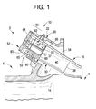
- Turbomachine 2 includes a compressor portion 4 operatively connected to a turbine portion 6.
- a combustor assembly 10 fluidly connects compressor portion 4 with turbine portion 6.
- Compressor portion 4 includes a compressor discharge 14 that passes compressor discharge air into combustor assembly 10.
- a portion of the combustor discharge air is employed for cooling various components of combustor assembly 10, and another portion of the compressor discharge air is mixed with fuel to form a combustible mixture that is combusted to form hot gases.
- the hot gases pass from combustor assembly 10 through a transition piece 16 into turbine portion 6.
- Turbine portion 6 converts thermal energy from the hot gases into mechanical, rotational energy used to power various systems such as generators, pumps and the like.
- combustor assembly 10 includes a combustor housing 20 having a first end 22 that extends to a second end (not shown).
- Combustor assembly 10 includes a combustor body 30 arranged within combustor housing 20.
- Combustor body 30 defines a combustor liner 34.
- Combustor liner 34 includes a first end portion 37 that extends to a second end portion 38 through a combustion chamber 40.
- Combustor assembly 10 also includes an cap assembly 50 mounted at first end 22 of combustor housing 20.
- Cap assembly 50 includes an end cover 52 and a forward casing 53.
- End cover 52 supports a plurality of fuel nozzles, one of which is indicated at 56, arranged in an annular array. Fuel nozzles 56 extend from end cover 52 toward combustion chamber 40. As will be detailed more fully below, fuel and air are mixed in forward casing 53 forming a combustible mixture that is passed to fuel nozzles 56. The combustible mixture is combusted and expanded in combustion chamber 40 and then passed through transition piece 16 toward turbine portion 6.
- Forward casing 53 includes a body 60 having a first flange 62 that is operatively connected to first end 22 of combustor housing 20 and a second flange 63 to which is mounted end cover 52.
- Forward casing 53 includes an outer barrel member 66 that extends about fuel nozzles 56 and defines, in part, a passage (not separately labeled) that conducts compressor discharge air from combustor housing 20 toward end cover 52.
- outer barrel member 66 includes a body member 67 having a first end section 68 that extends to a second end section 69. Second end section 69 abuts first end portion 37 of combustor liner 34.
- outer barrel member 66 includes a liner stop 80.
- Liner stop 80 includes a stepped lip portion 83 provided at second end section 69 of outer barrel member 66.
- Stepped lip portion 83 includes a first wall section 86 and a second wall section 87.
- First wall section 86 extends from body member 67 radially toward a centerline (not separately labeled) of combustor assembly 10.
- Second wall section 87 is radially offset from body member 67 and extends substantially perpendicularly from first wall section 86.
- Cap assembly 50 is positioned at combustor housing 20 with outer barrel member 66 being aligned with combustor liner 34.
- Cap assembly 50 is mounted and secured to combustor housing 20 with stepped lip portion 83 extending into first end portion 37 of combustor liner 34 forming a substantially smooth liner-to-outer barrel member interface 90.
- first wall section 86 restricts axial movement of combustion liner 34 while stepped lip portion 83 establishes a smooth transition between combustion liner 34 and outer barrel member 66.
- the smooth transition established between combustion liner 34 and outer barrel portion 66 promotes a substantially laminar flow of compressor discharge air passing from compressor portion 4 along combustor body 30.
- liner stop 80 limit or restrict axial movement of combustion liner 34 but also conditions fluid flow to fuel nozzles 56.
- liner stop 80 is provided with a seal member 94 that includes a plurality of seal segments, one of which is indicated at 96, secured to second wall section 87 to form a hula seal 99.
- Seal member 94 restricts fluid flow passing over combustion liner 34 toward end cover 52 from escaping through liner-to-outer barrel member interface 90. That is, when outer barrel member 66 inserted into combustion liner 34, first end portion 37 compresses seal member 84 to form a more robust seal at liner-to-outer barrel member interface 90.
- stepped lip portion 83 could alternatively be formed on first end portion 37 of combustion liner 34.
- a seal member formed from multiple seal segments it should be understood that a continuous seal could also be employed.
Landscapes
- Engineering & Computer Science (AREA)
- Chemical & Material Sciences (AREA)
- Combustion & Propulsion (AREA)
- Mechanical Engineering (AREA)
- General Engineering & Computer Science (AREA)
- Turbine Rotor Nozzle Sealing (AREA)
Applications Claiming Priority (1)
| Application Number | Priority Date | Filing Date | Title |
|---|---|---|---|
| US13/150,319 US20120304655A1 (en) | 2011-06-01 | 2011-06-01 | Turbomachine combustor assembly including a liner stop |
Publications (1)
| Publication Number | Publication Date |
|---|---|
| EP2530385A2 true EP2530385A2 (de) | 2012-12-05 |
Family
ID=46148759
Family Applications (1)
| Application Number | Title | Priority Date | Filing Date |
|---|---|---|---|
| EP12169883A Withdrawn EP2530385A2 (de) | 2011-06-01 | 2012-05-29 | Brennkammergehäuseanordnung einer Turbomaschine mit einem Einlagenstopp |
Country Status (3)
| Country | Link |
|---|---|
| US (1) | US20120304655A1 (de) |
| EP (1) | EP2530385A2 (de) |
| CN (1) | CN102809174A (de) |
Families Citing this family (1)
| Publication number | Priority date | Publication date | Assignee | Title |
|---|---|---|---|---|
| US9650958B2 (en) * | 2014-07-17 | 2017-05-16 | General Electric Company | Combustor cap with cooling passage |
Family Cites Families (6)
| Publication number | Priority date | Publication date | Assignee | Title |
|---|---|---|---|---|
| US6722135B2 (en) * | 2002-01-29 | 2004-04-20 | General Electric Company | Performance enhanced control of DLN gas turbines |
| US6895757B2 (en) * | 2003-02-10 | 2005-05-24 | General Electric Company | Sealing assembly for the aft end of a ceramic matrix composite liner in a gas turbine engine combustor |
| US6955038B2 (en) * | 2003-07-02 | 2005-10-18 | General Electric Company | Methods and apparatus for operating gas turbine engine combustors |
| US7284378B2 (en) * | 2004-06-04 | 2007-10-23 | General Electric Company | Methods and apparatus for low emission gas turbine energy generation |
| US7762075B2 (en) * | 2007-08-14 | 2010-07-27 | General Electric Company | Combustion liner stop in a gas turbine |
| US8171737B2 (en) * | 2009-01-16 | 2012-05-08 | General Electric Company | Combustor assembly and cap for a turbine engine |
-
2011
- 2011-06-01 US US13/150,319 patent/US20120304655A1/en not_active Abandoned
-
2012
- 2012-05-29 EP EP12169883A patent/EP2530385A2/de not_active Withdrawn
- 2012-06-01 CN CN2012101917216A patent/CN102809174A/zh active Pending
Non-Patent Citations (1)
| Title |
|---|
| None |
Also Published As
| Publication number | Publication date |
|---|---|
| US20120304655A1 (en) | 2012-12-06 |
| CN102809174A (zh) | 2012-12-05 |
Similar Documents
| Publication | Publication Date | Title |
|---|---|---|
| EP2525151B1 (de) | Brennkammeranordnung für eine Turbomaschine | |
| JP6134580B2 (ja) | モノリシックノズル部品を含むターボ機械燃焼器ノズル及びその形成方法 | |
| US10196975B2 (en) | Turboprop engine with compressor turbine shroud | |
| US20160017755A1 (en) | Common joint for a combustor, diffuser, and tobi of a gas turbine engine | |
| EP2581664A1 (de) | Ringförmiges Strömungsbedingungselement für eine Gasturbomaschine-Brenneranordnung | |
| US8813501B2 (en) | Combustor assemblies for use in turbine engines and methods of assembling same | |
| US8683805B2 (en) | Injector seal for a gas turbomachine | |
| US20110162377A1 (en) | Turbomachine nozzle | |
| US10634344B2 (en) | Fuel nozzle assembly with fuel purge | |
| US9546600B2 (en) | Nozzle having an orifice plug for a gas turbomachine | |
| US20160160667A1 (en) | Discourager seal for a turbine engine | |
| EP4524470A1 (de) | Gasturbinentriebwerk und brennstoffdüse dafür | |
| US8276390B2 (en) | Method and system for providing a splitter to improve the recovery of compressor discharge casing | |
| US8474267B2 (en) | Radial turbine engine floating ring seal | |
| EP2530385A2 (de) | Brennkammergehäuseanordnung einer Turbomaschine mit einem Einlagenstopp | |
| KR20190126778A (ko) | 축방향으로 단계적인 연료 분사를 갖는 연소 시스템 | |
| US20150338101A1 (en) | Turbomachine combustor including a combustor sleeve baffle | |
| KR101408140B1 (ko) | 가스터빈 압축기의 반경방향 디스윌러 베인의 고정구조 | |
| EP2589878A2 (de) | Brennkammeranordnung für eine Gasturbomaschine | |
| US20180238239A1 (en) | Endcover Assembly for a Combustor | |
| KR102570813B1 (ko) | 연료 공급 조립체 및 관련 방법 | |
| US10041416B2 (en) | Combustor seal system for a gas turbine engine | |
| US20150047358A1 (en) | Inner barrel member with integrated diffuser for a gas turbomachine |
Legal Events
| Date | Code | Title | Description |
|---|---|---|---|
| PUAI | Public reference made under article 153(3) epc to a published international application that has entered the european phase |
Free format text: ORIGINAL CODE: 0009012 |
|
| AK | Designated contracting states |
Kind code of ref document: A2 Designated state(s): AL AT BE BG CH CY CZ DE DK EE ES FI FR GB GR HR HU IE IS IT LI LT LU LV MC MK MT NL NO PL PT RO RS SE SI SK SM TR |
|
| AX | Request for extension of the european patent |
Extension state: BA ME |
|
| STAA | Information on the status of an ep patent application or granted ep patent |
Free format text: STATUS: THE APPLICATION IS DEEMED TO BE WITHDRAWN |
|
| 18D | Application deemed to be withdrawn |
Effective date: 20141202 |