EP2530401B1 - Chauffage hydronique de pompe à chaleur - Google Patents
Chauffage hydronique de pompe à chaleur Download PDFInfo
- Publication number
- EP2530401B1 EP2530401B1 EP12170277.3A EP12170277A EP2530401B1 EP 2530401 B1 EP2530401 B1 EP 2530401B1 EP 12170277 A EP12170277 A EP 12170277A EP 2530401 B1 EP2530401 B1 EP 2530401B1
- Authority
- EP
- European Patent Office
- Prior art keywords
- heating medium
- port
- pipe
- outward
- heat pump
- Prior art date
- Legal status (The legal status is an assumption and is not a legal conclusion. Google has not performed a legal analysis and makes no representation as to the accuracy of the status listed.)
- Not-in-force
Links
- 238000010438 heat treatment Methods 0.000 claims description 305
- XLYOFNOQVPJJNP-UHFFFAOYSA-N water Substances O XLYOFNOQVPJJNP-UHFFFAOYSA-N 0.000 claims description 109
- 239000003507 refrigerant Substances 0.000 claims description 81
- 239000012212 insulator Substances 0.000 description 20
- 238000010276 construction Methods 0.000 description 19
- 229920003020 cross-linked polyethylene Polymers 0.000 description 9
- 239000004703 cross-linked polyethylene Substances 0.000 description 9
- 238000010586 diagram Methods 0.000 description 9
- 238000005516 engineering process Methods 0.000 description 7
- 230000001965 increasing effect Effects 0.000 description 7
- POIUWJQBRNEFGX-XAMSXPGMSA-N cathelicidin Chemical compound C([C@@H](C(=O)N[C@@H](CCCNC(N)=N)C(=O)N[C@@H](CCCCN)C(=O)N[C@@H](CO)C(=O)N[C@@H](CCCCN)C(=O)N[C@@H](CCC(O)=O)C(=O)N[C@@H](CCCCN)C(=O)N[C@@H]([C@@H](C)CC)C(=O)NCC(=O)N[C@@H](CCCCN)C(=O)N[C@@H](CCC(O)=O)C(=O)N[C@@H](CC=1C=CC=CC=1)C(=O)N[C@@H](CCCCN)C(=O)N[C@@H](CCCNC(N)=N)C(=O)N[C@@H]([C@@H](C)CC)C(=O)N[C@@H](C(C)C)C(=O)N[C@@H](CCC(N)=O)C(=O)N[C@@H](CCCNC(N)=N)C(=O)N[C@@H]([C@@H](C)CC)C(=O)N[C@@H](CCCCN)C(=O)N[C@@H](CC(O)=O)C(=O)N[C@@H](CC=1C=CC=CC=1)C(=O)N[C@@H](CC(C)C)C(=O)N[C@@H](CCCNC(N)=N)C(=O)N[C@@H](CC(N)=O)C(=O)N[C@@H](CC(C)C)C(=O)N[C@@H](C(C)C)C(=O)N1[C@@H](CCC1)C(=O)N[C@@H](CCCNC(N)=N)C(=O)N[C@@H]([C@@H](C)O)C(=O)N[C@@H](CCC(O)=O)C(=O)N[C@@H](CO)C(O)=O)NC(=O)[C@H](CC=1C=CC=CC=1)NC(=O)[C@H](CC(O)=O)NC(=O)CNC(=O)[C@H](CC(C)C)NC(=O)[C@@H](N)CC(C)C)C1=CC=CC=C1 POIUWJQBRNEFGX-XAMSXPGMSA-N 0.000 description 6
- 239000007788 liquid Substances 0.000 description 6
- 238000012423 maintenance Methods 0.000 description 4
- 238000000034 method Methods 0.000 description 3
- 230000002093 peripheral effect Effects 0.000 description 3
- 230000002708 enhancing effect Effects 0.000 description 2
- 239000011347 resin Substances 0.000 description 2
- 229920005989 resin Polymers 0.000 description 2
- 238000011144 upstream manufacturing Methods 0.000 description 2
- 238000010792 warming Methods 0.000 description 2
- RYGMFSIKBFXOCR-UHFFFAOYSA-N Copper Chemical compound [Cu] RYGMFSIKBFXOCR-UHFFFAOYSA-N 0.000 description 1
- 229920006328 Styrofoam Polymers 0.000 description 1
- 230000002745 absorbent Effects 0.000 description 1
- 239000002250 absorbent Substances 0.000 description 1
- 230000005494 condensation Effects 0.000 description 1
- 238000009833 condensation Methods 0.000 description 1
- 229910052802 copper Inorganic materials 0.000 description 1
- 239000010949 copper Substances 0.000 description 1
- 230000002950 deficient Effects 0.000 description 1
- 230000006866 deterioration Effects 0.000 description 1
- 230000000694 effects Effects 0.000 description 1
- 238000009413 insulation Methods 0.000 description 1
- 239000000463 material Substances 0.000 description 1
- 238000004806 packaging method and process Methods 0.000 description 1
- 239000008261 styrofoam Substances 0.000 description 1
Images




Classifications
-
- F—MECHANICAL ENGINEERING; LIGHTING; HEATING; WEAPONS; BLASTING
- F24—HEATING; RANGES; VENTILATING
- F24H—FLUID HEATERS, e.g. WATER OR AIR HEATERS, HAVING HEAT-GENERATING MEANS, e.g. HEAT PUMPS, IN GENERAL
- F24H4/00—Fluid heaters characterised by the use of heat pumps
- F24H4/02—Water heaters
- F24H4/04—Storage heaters
-
- F—MECHANICAL ENGINEERING; LIGHTING; HEATING; WEAPONS; BLASTING
- F24—HEATING; RANGES; VENTILATING
- F24D—DOMESTIC- OR SPACE-HEATING SYSTEMS, e.g. CENTRAL HEATING SYSTEMS; DOMESTIC HOT-WATER SUPPLY SYSTEMS; ELEMENTS OR COMPONENTS THEREFOR
- F24D11/00—Central heating systems using heat accumulated in storage masses
- F24D11/02—Central heating systems using heat accumulated in storage masses using heat pumps
- F24D11/0214—Central heating systems using heat accumulated in storage masses using heat pumps water heating system
-
- F—MECHANICAL ENGINEERING; LIGHTING; HEATING; WEAPONS; BLASTING
- F24—HEATING; RANGES; VENTILATING
- F24H—FLUID HEATERS, e.g. WATER OR AIR HEATERS, HAVING HEAT-GENERATING MEANS, e.g. HEAT PUMPS, IN GENERAL
- F24H9/00—Details
- F24H9/14—Arrangements for connecting different sections, e.g. in water heaters
- F24H9/142—Connecting hydraulic components
-
- F—MECHANICAL ENGINEERING; LIGHTING; HEATING; WEAPONS; BLASTING
- F24—HEATING; RANGES; VENTILATING
- F24H—FLUID HEATERS, e.g. WATER OR AIR HEATERS, HAVING HEAT-GENERATING MEANS, e.g. HEAT PUMPS, IN GENERAL
- F24H9/00—Details
- F24H9/14—Arrangements for connecting different sections, e.g. in water heaters
- F24H9/148—Arrangements of boiler components on a frame or within a casing to build the fluid heater, e.g. boiler
Definitions
- the present invention relates to a heat pump hydronic heater which heats a heating medium such as water and antifreezing liquid to warm up a room.
- a conventional heat pump hydronic heater of this kind there is one including a refrigerant circuit, a cistern and a circulation.
- the refrigerant circuit is formed by annularly connecting a compressor, a water refrigerant heat exchanger, decompressing means and an evaporator to one another.
- the water refrigerant heat exchanger receives supply of a refrigerant from this refrigerant circuit, and heats water.
- the cistern is connected to this water refrigerant heat exchanger.
- the circulation pump supplies hot water to a separated place.
- An outdoor unit is vertically divided by a horizontal parting plate. The cistern, the circulation pump and a hot water header are placed above the horizontal parting plate (see patent documents 1 and 2 for example).
- Figs. 9 are upper surface interior views and a front interior view of a conventional heat pump hydronic heater 100 described in patent document 1.
- a outdoor unit 100 includes a cistern 101 and a circulation pump 102.
- the cistern 101 replenishes a heating medium such as water and antifreezing liquid, and functions as a buffer of an expanded heating medium.
- the circulation pump 102 supplies hot water to an external radiator 110 (such as floor heating system and fan convector) installed at a separated place.
- An entire periphery of the outdoor unit 100 is covered with an exterior frame 103.
- An interior of the outdoor unit 100 is vertically divided by a vertically-parting plate 105, a heat pump apparatus 104 is disposed below the vertically-parting plate 105, and the cistern 101 and the circulation pump 102 are disposed above the vertically-parting plate 105.
- a heating medium outward port 106 and a heating medium return port 107 are disposed above the vertically-parting plate 105.
- the heating medium outward port 106 and the heating medium return port 107 connect the external radiator 110 and a pipe 109 to each other.
- the heating medium outward port 106 and the heating medium return port 107 are also disposed above the horizontal parting plate 105 such that they are oriented sideway.
- a pipe cover 108 in which a power supply line or the like is accommodated is provided on a right side of the heat pump apparatus 104.
- Fig. 10 is a working diagram in which the pipe 109 through which a heating medium is circulated to the outdoor unit 100 is connected to the external radiator 110 shown in Fig. 9 .
- the heating medium outward port 106, the heating medium return port 107 disposed on an upper and rear portion of the heat pump apparatus 104 and the pipe 109 are connected to each other, and they are connected to the external radiator 110 through a rear portion of the outdoor unit 100.
- patent documents 1 and 2 have a problem that since the cistern 101 and the circulation pump 102 are disposed above the outdoor unit 100, a sheath body becomes large, and conditions that the outdoor unit 100 is installed are limited.
- the pipe 109 connected to the heating medium outward port 106 and the heating medium return port 107 becomes long, and there is a problem that efficiency is deteriorated.
- Patent document 3 describes a heat pump hydronic heater disclosing all features of the preamble of claim 1 attached.
- the present invention has been accomplished to solve the above problems, and it is an object of the invention to provide a heat pump hydronic heater having high workability and improved efficiency.
- the present invention provides a heat pump hydronic heater which is defined in claim 1 attached and in which a compressor, a water refrigerant heat exchanger, decompressing means and an evaporator which configure a refrigerant circuit are accommodated in a sheath body, the sheath body has a heating medium outward port and a heating medium return port connected to the water refrigerant heat exchanger through a hot water circuit, the heating medium outward port and the heating medium return port are connected to an external radiator through a pipe, a heating medium heated by the water refrigerant heat exchanger circulates in the external radiator, and the heating medium dissipates heat in the external radiator, characterized in that a convex portion is provided on a side of the sheath body, and the heating medium outward port and the heating medium return port are disposed on the convex portion wherein the heating medium outward port is disposed outside of the sheath body, and the heating medium return port is disposed inside of the sheath body.
- a first aspect of the invention provides a heat pump hydronic heater in which a compressor, a water refrigerant heat exchanger, decompressing means and an evaporator which configure a refrigerant circuit are accommodated in a sheath body, the sheath body has a heating medium outward port and a heating medium return port connected to the water refrigerant heat exchanger through a hot water circuit, the heating medium outward port and the heating medium return port are connected to an external radiator through a pipe, a heating medium heated by the water refrigerant heat exchanger circulates in the external radiator, and the heating medium dissipates heat in the external radiator, characterized in that a convex portion is provided on a side of the sheath body, and the heating medium outward port and the heating medium return port are disposed on the convex portion.
- a power supply line is also connected to a right side of the outdoor unit, it is necessary to secure a constant distance from the sidewall as a maintenance space, but if the pipe is routed rightward, its space can be utilized effectively.
- the heating medium outward port and the heating medium return port are disposed substantially horizontally, and openings of the heating medium outward port and the heating medium return port are oriented rearward of the sheath body.
- pipes connected to the heating medium outward port and the heating medium return port can be routed substantially in parallel to each other.
- the pipes does not close the evaporator even when the pipes are routed toward the evaporator, and performance is not deteriorated.
- the heating medium outward port is disposed outside of the sheath body, and the heating medium return port is disposed inside of the sheath body.
- the heating medium outward port is disposed outward of the heating medium return port. Therefore, when the pipes are routed toward the back surface of the outdoor unit, the high temperature heating medium which flows out from the heating medium outward port passes outside and exchanges heat by the external radiator and the temperature of the heating medium becomes low. The low temperature heating medium passes in the vicinity of the outdoor unit and the evaporator, and returns to the heating medium return port.
- the evaporator is in a low temperature state.
- the heating medium outward pipe through which a high temperature heating medium flows is disposed at a location separated from the low temperature evaporator.
- the heating medium return pipe whose temperature is lowered is disposed at an inner location. According to this configuration, a high temperature side of the pipe is not cooled, the heating medium is sent to the external radiator while maintaining its high temperature.
- the heating medium which dissipates heat in the external radiator passes through a position close to the evaporator, temperature of the heating medium is further lowered and the heating medium is sent to the water refrigerant heat exchanger.
- COP can be enhanced and the energy-saving technology can further be enhanced.
- the heat pump hydronic heater further includes at least one more heating medium outward port and at least one more heating medium return port, the plurality of heating medium outward ports are arranged side by side in a vertical direction, and the plurality of heating medium return ports are arranged side by side in the vertical direction.
- the pipes connected to the heating medium outward port and the heating medium return port can compactly be accommodated below the outdoor unit, it becomes easy to route the pipe and the construction performance is enhanced.
- the heating medium outward port and the heating medium return port are arranged vertically and they are disposed substantially horizontally. According to this configuration, the plurality of heating medium outward ports and the plurality of heating medium return ports can be disposed collectively below the side of the outdoor unit.
- the pipes can be arranged at the lower location compactly.
- the heat pump hydronic heater further includes a cistern in which the heating medium is stored, and a circulation pump which circulates the heating medium, and the circulation pump and the cistern are disposed such that they project rearward of the sheath body.
- the pipe is routed in the left direction of the outdoor unit, but when the pipe is routed in the right direction, since the evaporator is not closed, no problem occurs. When the pipe is routed rearward also, no problem occurs. The problem in terms of performance occurs only when the pipe is routed in the right direction.
- the heating medium outward port and the heating medium return port are disposed in a port mounting tool which is the convex portion, and the port mounting tool is provided with a port mounting tool cover which can be attached and detached from outside.
- the heating medium outward port and the heating medium return port are fixed to the port mounting tool disposed sideway of the sheath body. According to this configuration, strength is enhanced, and strength when the pipe is fixed at the time of construction can be secured.
- the heating medium outward port is a thermally-actuated valve.
- the thermally-actuated valve 20 opens and closes in accordance with the external radiators which are used, and the thermally-actuated valve is controlled so that hot water flows only to a necessary external radiator.
- a flow rate of heated heating medium can be controlled in accordance with status of use of the external radiator, and usability and energy-saving technology are enhanced.
- a heat pump hydronic heater of a first embodiment of the present invention will be described based on Figs. 1 to 8 .
- the heat pump hydronic heater includes an outdoor unit 1 and external radiators 2.
- the outdoor unit 1 heats a heating medium such as water and antifreezing liquid.
- the external radiators 2 are connected to the outdoor unit 1 through pipes 3.
- the heating medium circulates through the outdoor unit 1 and the external radiators 2.
- Each of the external radiators 2 is a panel external radiator such as a floor heating system, but the external radiator 2 may be a radiator such as a fan convector including a panel heater or a blast fan 9.
- Each of the pipes 3 includes a heating medium outward pipe 3a and a heating medium return pipe 3b.
- the heating medium heated by the outdoor unit 1 is sent to the external radiators 2 through the pipes 3 (heating medium outward pipe 3a), and warms up a room where the external radiator 2 is installed.
- the outdoor unit 1 is a heat source thereof.
- the outdoor unit 1 as the heat pump heat source is provided therein with the following parts.
- the outdoor unit 1 includes a compressor 4 which compresses a refrigerant, a water refrigerant heat exchanger 5 which exchanges heat between a heating medium and a refrigerant, an expansion valve 6 which is decompressing means, and an evaporator 7.
- the compressor 4, the water refrigerant heat exchanger 5, the decompressing means 6 and the evaporator 7 are annularly connected to one another to configure a refrigerant circuit 8, and a refrigerant circulates through the refrigerant circuit 8.
- the blast fan 9 conveys air to the evaporator 7, and promotes the heat-exchanging ability of the evaporator 7.
- the water refrigerant heat exchanger 5 is formed from a copper pipe having high thermal conductivity, and is of double pipe structure including a refrigerant pipe 5a disposed on an outer side and a water pipe 5b disposed on an inner side.
- a refrigerant flows between an inner peripheral surface of the refrigerant pipe 5a and an outer peripheral surface of the water pipe 5b, and a heating medium flows in the water pipe 5b.
- a flowing direction of the refrigerant and a flowing direction of the heating medium are opposite from each other.
- a condensation temperature sensor 10 is brazed to and mounted on the water refrigerant heat exchanger 5.
- a compressor outlet temperature sensor 11 is provided in a compressor discharge pipe 12 of the compressor 4.
- An air heat exchanging outlet temperature sensor 13 is provided in an air heat exchanging outlet pipe 14 of the evaporator 7.
- the outdoor unit 1 includes a hot water circuit 15.
- the hot water circuit 15 includes a circulation pump 16.
- the circulation pump 16 is disposed upstream of the water refrigerant heat exchanger 5.
- the hot water circuit 15 is connected to the pipe 3, and the circulation pump 16 circulates a heating medium between the external radiator 2 and the water refrigerant heat exchanger 5.
- a cistern 17 is disposed upstream of the circulation pump 16.
- the cistern 17 adjusts an amount of a heating medium which circulates through the water refrigerant heat exchanger 5, the hot water circuit 15, the pipe 3 and the external radiator 2. If the circulation amount becomes deficient, the cistern 17 replenishes the heating medium, and if the circulation amount increases due to expansion, the cistern 17 stores the heating medium.
- the cistern 17 includes a cap 18 which opens for replenishing the heating medium, and a water level sensor 19 which detects a water level in the cistern 17.
- An outward-side terminal of the hot water circuit 15 includes thermally-actuated valves 20.
- the plurality of external radiators 2 includes the thermally-actuated valves 20.
- the thermally-actuated valves 20 provided on the external radiator 2 which is used are opened, the thermally-actuated valves 20 provided in the external radiator 2 which is not used or the thermally-actuated valves 20 which are not connected to the external radiator 2 are closed, and control is performed such that hot water flows only to the required external radiator 2.
- An outlet side of the hot water circuit 15 includes heating medium outward ports 21, and an inlet side of the hot water circuit 15 includes heating medium return ports 23.
- the heating medium outward ports 21 are provided downstream of the thermally-actuated valve 20, and the pipe 3 is connected to the heating medium outward ports 21. When all of the external radiators 2 are not used, the thermally-actuated valves 20 are closed.
- thermally-actuated valves 20 are used at four locations in Fig. 8 , the thermally-actuated valve 20 may be used at one location or five or more locations.
- the heating medium may flow directly to the external radiator 2 without using the thermally-actuated valve 20.
- An outward header pipe 22 divides the hot water circuit 15 into the plurality of circuits, and connects the plurality of thermally-actuated valves 20. When the number of thermally-actuated valves 20 is one, the thermally-actuated valve 20 is connected to the hot water circuit 15 without using the outward header pipe 22.
- the heating medium return ports 23 are connected to the pipe 3. Hot water dissipates heat in the external radiator 2 and temperature thereof is lowered, and the hot water returns to the pipe 3. Then number of heating medium return ports 23 is the same as that of the thermally-actuated valves 20, and the number is four in Fig. 7 . That is, when the thermally-actuated valve 20 is used at one location, the heating medium return port 23 is also used at one location.
- the heating medium return ports 23 are connected to the hot water circuit 15 (return port heating medium pipe 44) through the return header 24.
- the heating medium return ports 23 are connected to the hot water circuit 15 (return port heating medium pipe 44) without using the return header 24.
- a water refrigerant heat exchanger inlet temperature sensor 25 measures temperature of a heating medium which enters the water refrigerant heat exchanger 5.
- a water refrigerant heat exchanger outlet temperature sensor 26 measures temperature of a heating medium on the side of the outlet of the water refrigerant heat exchanger 5.
- a control device 27 controls various actuators and sensors of the heat pump hydronic heater.
- a remote control unit 28 is used when a user operates the heat pump water heater or carries out various setting operations.
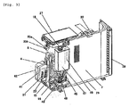
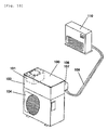
- Figs. 1 to 7 show the outdoor unit shown in the refrigerant circuit and hot water circuit diagram of the heat pump hydronic heater shown in Fig. 8 , wherein Figs. 1 to 4 are interior perspective view, Figs. 5 is an external perspective view and Figs. 6 and 7 are working diagrams. The same members as those shown in Fig. 8 are designated with the same symbols.
- the water refrigerant heat exchanger 5 is of a double pipe structure including the refrigerant pipe 5a disposed outside and the water pipe 5b.
- the water refrigerant heat exchanger 5 is placed on the bottom plate 29.
- the pipe 3 of the double pipe structure has a spiral shape so that the heat exchanger can be made compact.
- the compressor discharge pipe 12 is connected to the water refrigerant heat exchanger 5.
- a refrigerant is compressed to a high pressure by the compressor 4 and is discharged out, and this refrigerant flows into the water refrigerant heat exchanger 5 from an uppermost front surface of the refrigerant pipe 5a.
- a heating medium moves from the water pipe 5b located at a lower most portion to the water pipe 5b located above the former water pipe 5b and is heated.
- the heating medium is heated to high temperature and density thereof is lowered, and the heating medium is guided from the water pipe 5b located at the upper portion into the pipe 3, a buoyant force is added and power of the circulation pump 16 can be reduced.
- the hot water circuit 15 which connects the water refrigerant heat exchanger 5, the thermally-actuated valves 20 and the heating medium return ports 23 to each other passes through the front surface of the compressor 4.
- the radiator heat insulator 30 shown in Fig. 4 is made of heat insulator such as Styrofoam to enhance heat insulating properties of the water refrigerant heat exchanger 5.
- the radiator heat insulator 30 includes a radiator upper heat insulator 30a and a radiator lower heat insulator 30b.
- the water refrigerant heat exchanger 5 is sandwiched between the radiator upper heat insulator 30a and the radiator lower heat insulator 30b.
- the radiator lower heat insulator 30b is placed on the bottom plate 29 such that the radiator heat insulator 30 engages with concavity and convexity on a flat surface of the bottom plate 29.
- radiator heat insulator 30 is disposed on an outer and upper side of the radiator heat insulator 30, and covers front, rear, left, right and upper surfaces of the radiator upper heat insulator 30a and the radiator lower heat insulator 30b.
- the radiator heat insulator 30 and another part are used as the cover body 31 in the drawing, the cover body 31 can also be used as the radiator heat insulator 30.
- portions of the radiator heat insulator 30 and the cover body 31 are cut so that the water refrigerant heat exchanger 5 can be seen in Fig. 4 , the actual radiator heat insulator 30 and cover body 31 are not cut.
- the evaporator 7 is bent into an L-shape to surround a rear side portion of the water refrigerant heat exchanger 5, and the evaporator 7 is placed on the bottom plate 29.
- the blast fan 9 is disposed in the evaporator 7 and above the cover body 31, the blast fan 9 makes air forcibly pass through the evaporator 7, and promotes the heat exchange between the air and a refrigerant.
- a blast motor 32 drives the blast fan 9, and a motor stage 33 holds the blast motor 32.
- the motor stage 33 is fixed to an upper surface of the cover body 31.
- a divider 34 isolates, from each other, a space in which the blast fan 9 and the water refrigerant heat exchanger 5 are disposed and a space in which the compressor 4 and the expansion valve 6 that is decompressing means are disposed.
- the control device 27 is placed above the divider 34.
- a power supply line connection terminal 35a and a remote control connection terminal 35b are provided on the right side of the control device 27.
- the sheath body 36 includes a front plate 37, a right plate 38, a left plate 39 and a ceiling plate 40.
- the front plate 37 which covers a front side
- the right plate 38 which covers a right side and a right and rear side
- the left plate 39 which covers a left side are mounted on the bottom plate 29.
- the ceiling plate 40 which covers an upper side is placed on the front plate 37, the right plate 38 and the left plate 39.
- the plurality of thermally-actuated valves 20 protrude outside of the right plate 38 and are vertically disposed at a location on a right side of the sheath body 36 and on a right and outer side of the compressor 4.
- the number of thermally-actuated valves 20 is one, the one thermally-actuated valve 20 is disposed outside of the right plate 38.
- a heating medium is heated by the water refrigerant heat exchanger 5 and it becomes hot water, and the thermally-actuated valve 20 sends this heating medium to the external radiator 2 through the pipe 3.
- Each of the thermally-actuated valves 20 is provided at its tip end with a heating medium outward port 21.
- the heating medium passes through the thermally-actuated valve 20 and the heating medium outward port 21, and is sent to the pipe 3 (see Fig. 7 for pipe 3).
- the plurality of heating medium return ports 23 likewise protrude outside of the right plate 38 on a side of the thermally-actuated valves 20 and are vertically disposed side by side and oriented substantially horizontally with the thermally-actuated valves 20.
- a heating medium dissipates heat in the external radiator 2 and temperature thereof is lowered. This heating medium is returned to the hot water circuit 15 by the heating medium return port 23.
- Openings of the heating medium outward ports 21 and the heating medium return ports 23 are oriented rearward of the sheath body 36.
- the thermally-actuated valves 20 and the heating medium return ports 23 are mounted on a port mounting tool 41.
- the port mounting tool 41 is fixed to the bottom plate 29.
- the port mounting tool cover 42 is provided on an outer side of the port mounting tool 41, and is held by the port mounting tool 41.
- the port mounting tool 41 and the port mounting tool cover 42 are mounted such that they protrude outward of the right side plate 38.
- the thermally-actuated valves 20, the heating medium return ports 23, the port mounting tool 41 on which the thermally-actuated valves 20 and the heating medium return ports 23 are mounted, and the port mounting tool cover 42 are disposed at locations protruding sideway from the sheath body 36 of the heat pump hydronic heater.
- the outward header pipe 22 is connected to the thermally-actuated valve 20, and the outward header pipe 22 and the water pipe 5b of the water refrigerant heat exchanger 5 are connected to each other through a thermally-actuated valve pipe 43 which is the hot water circuit 15.
- the water refrigerant heat exchanger outlet temperature sensor 26 is mounted on the thermally-actuated valve pipe 43.
- the cistern 17 protrudes rearward of the right plate 38 existing behind the compressor 4.
- the return port heating medium pipe 44 is connected to a lower surface of the cistern 17.
- the return port heating medium pipe 44 is connected to the return header 24 which is integrally formed on the heating medium return port 23.
- a heating medium dissipates heat in the external radiator 2 and temperature thereof is lowered. The heating medium is guided to the cistern 17 by the return port heating medium pipe 44.
- the cistern 17 functions to absorb volume expansion of the heating medium which is heated from low temperature to high temperature and whose volume is increased. Especially when antifreezing liquid having large volume expansion ratio is used as the heating medium, a capacity of the cistern 17 is determined so that the heating medium does not overflow.
- the cap 18 is provided above the cistern 17. The cap 18 is detached and a heating medium is replenished to the cistern 17.
- a slit is formed in a portion of the cap 18, and increased pressure in the cistern 17 is released from the slit.
- the water level sensor 19 provided in the cistern 17 detects a water level in the cistern 17, and if the water level is lowered, the water level sensor 19 issues a warning to a user and displays the warming on the remote control unit 28, thereby urging the user to replenish the heating medium.
- the circulation pump 16 is disposed below the cistern 17. Like the cistern 17, the circulation pump 16 protrudes toward a back surface of the right plate 38 located behind the compressor 4.
- a pump outward pipe 45 which is pulled out from a lower portion of the cistern 17 is connected to the circulation pump 16 disposed below the cistern 17, and a heating medium flows through the pump outward pipe 45 from an upper side to a lower side.
- the cistern 17, the pump outward pipe 45 and the circulation pump 16 are disposed at positions protruding toward the back surface of the right plate 38 located behind the compressor 4.
- the circulation pump 16 carries out operation such that hot water forcibly circulates through the hot water circuit 15.
- the water refrigerant heat exchanger 5 and the pump outward pipe 46 are connected to the circulation pump 16.
- a water refrigerant heat exchanger inlet temperature sensor 25 which measures temperature of hot water entering the water refrigerant heat exchanger 5 is mounted on the pump outlet pipe 46.
- Figs. 5 are external perspective views of the heat pump hydronic heater in a state where the sheath body 36 is mounted.
- the circulation pump 16 and the cistern 17 are covered with a rear sheath body 47 which protrudes in a convex form rearward of the right plate 38 of the sheath body 36 behind the compressor 4.
- the rear sheath body 47 prevents water from entering the circulation pump 16 and the cistern 17 from outside.
- the rear sheath body 47 includes a rear bottom plate 47a located at a lowermost portion, a rear side plate 47b which covers a side and a rear upper plate 47c located at an uppermost portion.
- a portion surrounded by a broken line A protrudes, in a convex form, rightward of the outdoor unit 1 on a side of the compressor 4.
- a portion surrounded by a broken line B is accommodated in the rear sheath body 47.
- the rear sheath body 47 is disposed behind the compressor 4, and is disposed behind the outdoor unit 1.
- a pipe cover 50 is provided on a right and outer side of the right plate 38, and the port mounting tool 41 and the port mounting tool cover 42 are mounted on the right plate 38 inside the pipe cover 50.
- the thermally-actuated valves 20 and the heating medium return ports 23 are mounted on the port mounting tool 41, thereby likewise preventing water from entering from outside.
- the front plate 37 of the sheath body 36 is provided with a transfer port 37a which is concentric with the blast fan 9.
- the transfer port 37a is provided with a bell mouth 37b.
- the bell mouth 37b has a squeezed or narrowed shape which is concentric with the blast fan 9, and which is curved in a substantially semi-circular radially outward form from its inner peripheral.
- a transfer grille 51 has a grid-shaped opening through which wind from the blast fan 9 passes.
- the transfer grille 51 is provided such that it protrudes forward of the transfer port 37a of the front plate 37, and the transfer grille 51 rectifies wind, thereby reducing noise, and also functions to protect such that a hand does not touch the blast fan 9.
- Figs. 6 and 7 are working diagrams in which the pipe 3 is mounted on the outdoor unit 1 and in Fig. 7 , the pipe cover 50 is mounted.
- An outdoor unit 1 is placed on a block base 52, and the outdoor unit 1 is held such that it floats by about 100 mm.
- the block base 52 is generally made of concrete or resin.
- a power supply line 53 is connected to the power supply line connection terminal 35a, and supplies a power supply to the outdoor unit 1.
- a remote control line 54 is connected to the remote control connection terminal 35b, supplies a power supply to the remote control 28, and sends and receives data.
- the pipe 3 is mounted on the heating medium outward port 21 and the heating medium return port 23.
- An interior of the pipe 3 is a crosslinked polyethylene pipe, and a heat insulator is provided outside of the crosslinked polyethylene pipe.
- the pipe 3 is connected to the external radiator 2, a heating medium heated by the outdoor unit 1 is sent from the heating medium outward port 21 to the external radiator 2 through the heating medium outward pipe 3a, thereby warming up a room.
- the heating medium whose heat is exchanged there and whose temperature is lowered passes through a heating medium return pipe 3b, returns to the heating medium return port 23, and the heating medium is again heated in the outdoor unit 1 of the heat pump hydronic heater, and these operations are repeated.
- the pipe 3 (heating medium outward pipe 3a, heating medium return pipe 3b) is rotated in a left direction of the body in Figs. 6 and 7 , but in the case of the right direction also, the pipe 3 is routed straightly in some cases. However, as shown in Fig. 7 , it is most difficult to route the pipe 3 in the left direction of the outdoor unit 1. It is necessary to avoid a case where the pipes 3 close the evaporator 7, an area of the evaporator 7 is reduced, a heat exchanging amount is reduced and efficiency is deteriorated.
- Fig. 6 shows a state where the pipe cover 50 is detached.
- Fig. 7 shows a state where after the pipes 3, the power supply line 53 and the remote control line 54 are mounted, the pipe cover 50 is mounted.
- the outdoor unit 1 is first placed on the block base 52 (or placement stage).
- the power supply line 53 is connected to the power supply line connection terminal 35a, and the remote control line 54 which is connected to the remote control 28 is connected to the remote control connection terminal 35b.
- the pipes 3 which are connected to the external radiators 2 are connected to the heating medium outward ports 21 which are connected to the thermally-actuated valves 20, and the pipes 3 are connected to the heating medium return ports 23 disposed on an inner side of the heating medium outward ports 21.
- the cap 18 of the cistern 17 is opened, and a heating medium is poured to a predetermined amount.
- the circulation pump 16 disposed below the cistern 17 is operated, and the heating medium is uniformly distributed to the hot water circuit 15, the pipe 3 and the external radiator 2.
- the compressor 4 If the operation of the outdoor unit 1 is started by the remote control 28, the compressor 4 is operated. Then, a refrigerant is compressed to a high pressure and is discharged. The refrigerant passes through the compressor discharge pipe 12, and is sent to the water refrigerant heat exchanger 5, and exchanges heat with a heating medium which is sent by the circulation pump 16 and the refrigerant dissipates heat. According to this operation, the heated heating medium is changed from a low temperature heating medium to a high temperature heating medium.
- a refrigerant which flows out from the water refrigerant heat exchanger 5 is decompressed and expanded by the expansion valve 6, is sent to the evaporator 7, exchanges heat with air which is sent by the blast fan 9, and while the refrigerant passes through the evaporator 7, the refrigerant is evaporated and gasified.
- the gasified refrigerant is sucked into the compressor 4, is again compressed, and this process is repeated, and the low temperature heating medium which passes through the water refrigerant heat exchanger 5 is gradually heated.
- a heating medium is heated in the water refrigerant heat exchanger 5 by operating the circulation pump 16, the heated heating medium is forcibly sent to the outward header pipe 22, the heating medium is divided into a plurality of locations (four locations in the drawing, but the heating medium is not divided in some cases), and they are sent to the thermally-actuated valves 20.
- One of the thermally-actuated valves 20 through which a heating medium flows to the external radiator 2 is set by the remote control unit 28, the set thermally-actuated valve 20 is opened, and other thermally-actuated valves 20 are closed.
- a heating medium passes through a pipe which is provided outside of the outdoor unit 1 via the thermally-actuated valve 20 and the heating medium outward port 21, and the heating medium is guided into the external radiator 2.
- the heating medium dissipates heat in the external radiator 2, and warms up a room where the external radiator 2 is installed.
- the heating medium which dissipates heat in the external radiator 2 and whose temperature is lowered passes through the pipe 3, and passes through the heating medium return pipe 3b and flows toward the heating medium return port 23 which is disposed inward of the heating medium outward port 21 in a substantially horizontal direction.
- the heating medium passes through the heating medium return port 23 and the return header 24, passes through the return port heating medium pipe 44 and enters the cistern 17 from a lower surface of the cistern 17.
- a constant amount of heating medium such as water and antifreezing liquid exists in the cistern 17 such that an air layer exists above the heating medium.
- the heating medium similarly passes through the pump outward pipe 45 from the lower surface of the cistern 17, is forcibly sucked into the circulation pump 16, and is forcibly sent to the pump outlet pipe 46 by the circulation pump 16, and the heating medium whose temperature is lowered is heated by the water refrigerant heat exchanger 5, and is again guided into the external radiator 2, and these operations are repeated, and the heating medium such as water and antifreezing liquid which dissipates heat in the external radiator 2 warms up a room.
- each of the pipes 3 (heating medium outward pipe 3a, heating medium return pipe 3b) is first mounted rearwardly on a convex portion of a right side of the outdoor unit 1, and the pipe cover 50 is mounted on the pipe 3.
- a method for this operation is substantially the same as construction of an air conditioner (in the case of the air conditioner, a pipe for connecting between the outdoor unit and the indoor unit is mounted in the same manner).
- the above convex portion is substantially equal to a location where a refrigerant pipe is connected in the air conditioner, even a non-skilled construction operator can easily construct.
- the pipe 3 (heating medium outward pipe 3a, heating medium return pipe 3b) is routed sideway of the outdoor unit 1, the pipe 3 can be routed from the side toward a back surface as shown in Fig. 6 or 7 , and a radius of curvature of the pipe 3 can be increased.
- a crosslinked polyethylene pipe of 10 ⁇ is used as the pipe 3 in many cases, and it is possible to secure a radius of curvature of R150 or higher which is regarded as a desired value.
- the heating medium outward port 21 and the heating medium return port 23 are mounted, and they are covered with the pipe cover 50 as shown in Fig. 7 .
- the crosslinked polyethylene pipe is mainly used as the pipe 3, a heat insulator is provided around the crosslinked polyethylene pipe as a covering material. It is known that the crosslinked polyethylene pipe is deteriorated by ultraviolet light such as sunlight, and there is fear that the crosslinked polyethylene pipe is cracked and water leaks.
- a connected portion of the crosslinked polyethylene pipe (pipe 3) with respect to the heating medium outward port 21 and the heating medium return port 23 has no heat insulator.
- the pipe cover 50 it is possible to shield the connected portion from the sunlight, and it is possible to prevent the deterioration and secure quality for long periods.
- the pipe cover 50 is made resin, it is desirable that ultraviolet light absorbent is mixed so that the ultraviolet light does not enter inside.
- the power supply line 53 and the remote control line 54 for the remote control 28 are also connected to the power supply line connection terminal 35a and the remote control connection terminal 35b on the right side of the outdoor unit 1. Hence, it is necessary to secure a constant distance from the sidewall as a maintenance space, but if the pipe 3 is routed rightward, its space can be utilized effectively.
- the pipes 3 heatating medium outward pipes 3a, heating medium return pipes 3b connected to the heating medium outward port 21 and the heating medium return port 23 can be routed substantially in parallel to each other.
- the pipes 3 does not close the evaporator 7 even when the pipes 3 are routed toward the evaporator 7, and performance is not deteriorated.
- the pipe 3 is routed in the left direction of the outdoor unit 1 of the heat pump hydronic heater, but when the pipe 3 is routed in the right direction, since the evaporator 7 is not closed, no problem occurs. When the pipe 3 is routed rearward also, no problem occurs. The problem in terms of performance occurs only when the pipe 3 (heating medium outward pipe 3a, heating medium return pipe 3b) is routed in the left direction.
- heating medium outward pipes 3a, heating medium return pipes 3b When the pipes 3 (heating medium outward pipes 3a, heating medium return pipes 3b) connected to the heating medium outward ports 21 and the heating medium return ports 23 are routed in the left direction of the outdoor unit 1, and the heating medium outward ports 21 are disposed outward of the heating medium return ports 23. Therefore, when the pipes 3 are routed toward the back surface of the outdoor unit 1, a high temperature heating medium which flows out from the heating medium outward ports 21 passes outward, heat of the heating medium is exchanged by the external radiator 2, and temperature of the heating medium is lowered. The low temperature heating medium passes through the heating medium return pipe 3b, passes in the vicinity of the outdoor unit 1 and the evaporator 7, and returns to the heating medium return port 23.
- the evaporator 7 is in a low temperature state.
- the heating medium outward pipe 3a through which a high temperature heating medium flows is disposed at a location separated from the low temperature evaporator 7.
- the heating medium return pipe 3b whose temperature is lowered is disposed at an inner location. According to this configuration, a high temperature side of the heating medium outward pipe 3a is not cooled, the heating medium is sent to the external radiator 2 while maintaining its high temperature.
- the heating medium which dissipates heat in the external radiator 2 passes through a position close to the evaporator 7, temperature of the heating medium is further lowered and the heating medium is sent to the water refrigerant heat exchanger 5.
- COP can be enhanced and the energy-saving technology can further be enhanced.
- the plurality of heating medium outward ports 21 and heating medium return ports 23 are provided (four in Figs. 1 and 3 as one example). Since the plurality of heating medium outward ports 21 and heating medium return ports 23 are vertically disposed side by side, the pipes 3 connected to the heating medium outward ports 21 and heating medium return ports 23 can compactly be accommodated below the outdoor unit 1, it becomes easy to route the pipes 3, and workability is enhanced.
- the plurality of heating medium outward ports 21 and heating medium return ports 23 are vertically disposed side by side substantially horizontally, the plurality of heating medium outward ports 21 and heating medium return ports 23 can be collectively disposed below the side of the outdoor unit 1. Especially when the plurality of pipes 3 are routed in the left direction of the heating outdoor unit 1, there is fear that the pipes 3 close the evaporator 7. However, the heating medium outward ports 21 and the heating medium return ports 23 can collectively be disposed as described above, it is possible to arrange the pipes 3 compactly at the low locations.
- the circulation pump 16 conveys a heating medium.
- the heating medium outward port 21 discharged a heating medium to the pipe 3 connected to the external radiator 2.
- the hot water circuit 15 connects the heating medium return port 23, the cistern 17, the circulation pump 16, the water refrigerant heat exchanger 5 and the heating medium outward port 21 to one another.
- the circulation pump 16 is disposed below the cistern 17.
- the rear sheath body 47 protrudes in a convex form from the sheath body 36 provided behind the compressor 4.
- the cistern 17 and the circulation pump 16 are accommodated in the rear sheath body 47.
- the heating medium outward port 21 and the heating medium return port 23 are mounted on the port mounting tool 41 which projects from the sheath body 36 in a convex form. According to this configuration, when the pipes 3 connected to the heating medium outward port 21 and the heating medium return port 23 are routed in the left direction of the outdoor unit 1, the pipes 3 are extended rearward and then, the pipes 3 pass through a rear portion of the outdoor unit 1.
- the pipes 3 are routed in the left direction of the outdoor unit 1, but when the pipes 3 are routed in the right direction, since the evaporator 7 is not closed, no problem occurs. When the pipe 3 is routed rearward also, no problem occurs. The problem in terms of performance occurs only when the pipe 3 is routed in the right direction.
- the heating medium outward port 21 has the thermally-actuated valve 20 which opens and closes the circulation of the heating medium, the thermally-actuated valve 20 opens and closes in accordance with the external radiators 2 which are used, and the thermally-actuated valve 20 is controlled so that a heating medium flows only to a necessary external radiator 2.
- An amount of heated heating medium which should flow can be controlled in accordance with status of use of the external radiator 2, and usability and energy-saving technology are enhanced.
- the rear sheath body 47 is provided behind the outdoor unit 1, and the pipe cover 50 is provided on the right side of the outdoor unit 1. Therefore, the outdoor unit 1 does not become extremely large. Therefore, increase in cost can be suppressed and cost can be reduced.
- the rear sheath body 47 of the outdoor unit 1 located at the rear position becomes large as compared with the air conditioner which is a base, but a projected area is not largely varied, packaging capacity is extremely increased, custody charge at the time of storage in warehouse is suppressed to the minimum, and the cost can be reduced.
- the present invention is extremely effective for maintaining the heat pump hydronic heater body as compact as possible, reducing noise and vibration, enhancing the performance, and enhancing the maintenance performance.
- the heat pump hydronic heater of the invention workability is high, and the efficiency is enhanced. Therefore, the heat pump hydronic heater of the invention is used for a heating system such as a floor heating system and a hot-water heating system.
Landscapes
- Engineering & Computer Science (AREA)
- Physics & Mathematics (AREA)
- Thermal Sciences (AREA)
- Chemical & Material Sciences (AREA)
- Combustion & Propulsion (AREA)
- Mechanical Engineering (AREA)
- General Engineering & Computer Science (AREA)
- Steam Or Hot-Water Central Heating Systems (AREA)
- Housings, Intake/Discharge, And Installation Of Fluid Heaters (AREA)
- Heat-Exchange Devices With Radiators And Conduit Assemblies (AREA)
Claims (6)
- Chauffage hydronique à pompe à chaleur (100) dans lequel un compresseur (4), un échangeur de chaleur eau-réfrigérant (5), des moyens de décompression (6) et un évaporateur (7) qui constituent un circuit de réfrigérant (8) sont logés dans un corps enveloppe (36),
ledit corps enveloppe (36) présente un raccord extérieur de milieu chauffant (21) et un raccord de retour de milieu chauffant (23) qui sont reliés audit échangeur de chaleur eau-réfrigérant (5) par un circuit d'eau chaude (15), ledit raccord extérieur de milieu chauffant (21) et ledit raccord de retour de milieu chauffant (23) sont reliés à un radiateur externe (2) par une conduite (3),
le chauffage a un milieu chauffant pour être chauffé par ledit échangeur de chaleur eau-réfrigérant (5) et pour le faire circuler dans le radiateur externe (2), et le milieu chauffant étant adapté pour dissiper de la chaleur dans le radiateur externe (2), dans lequel
une portion convexe (41) est prévue sur un côté du corps enveloppe (36), et le raccord extérieur de milieu chauffant (21) et le raccord de retour de milieu chauffant (23) sont disposés sur la portion convexe (41),
caractérisé par le fait que le raccord extérieur de milieu chauffant (21) est disposé à l'extérieur du corps enveloppe (36) et que le raccord de retour de milieu chauffant (23) est disposé à l'intérieur du corps enveloppe (36). - Chauffage hydronique à pompe à chaleur (100) selon la revendication 1, caractérisé par le fait que le raccord extérieur de milieu chauffant (21) et le raccord de retour de milieu chauffant (23) sont disposés pour l'essentiel horizontalement, et des ouvertures du raccord extérieur de milieu chauffant (21) et du raccord de retour de milieu chauffant (23) sont orientées vers l'arrière du corps enveloppe (36).
- Chauffage hydronique à pompe à chaleur (100) selon la revendication 1 ou 2, comprenant en outre au moins un autre raccord extérieur de milieu chauffant et au moins un autre raccord de retour de milieu chauffant, caractérisé par le fait que la pluralité de raccords extérieurs de milieu chauffant (21) sont disposés côte à côte dans la direction verticale et la pluralité de raccords de retour de milieu chauffant (23) sont disposés côte à côte dans la direction verticale.
- Chauffage hydronique à pompe à chaleur (100) selon l'une quelconque des revendications 1 à 3, comprenant en outre :un réservoir (17) dans lequel est stocké le milieu chauffant etune pompe de circulation (16) qui fait circuler le milieu chauffant, caractérisé par le fait que ladite pompe de circulation (16) et ledit réservoir (17) sont agencés de telle sorte qu'ils font saillie de la face arrière du corps enveloppe (36).
- Chauffage hydronique à pompe à chaleur (100) selon l'une quelconque des revendications 1 à 4, caractérisé par le fait que le raccord extérieur de milieu chauffant (21) et le raccord de retour de milieu chauffant (23) sont disposés dans un outil de montage de raccord qui est la portion convexe (41), et ledit outil de montage de raccord (41) est équipé d'un couvercle d'outil de montage de raccord (42) qui peut être attaché et détaché de l'extérieur.
- Chauffage hydronique à pompe à chaleur (100) selon l'une quelconque des revendications 1 à 5, caractérisé par le fait que le raccord extérieur de milieu chauffant (21) est une vanne (20) à commande thermique.
Applications Claiming Priority (1)
| Application Number | Priority Date | Filing Date | Title |
|---|---|---|---|
| JP2011121360A JP5845441B2 (ja) | 2011-05-31 | 2011-05-31 | ヒートポンプ温水暖房装置 |
Publications (3)
| Publication Number | Publication Date |
|---|---|
| EP2530401A2 EP2530401A2 (fr) | 2012-12-05 |
| EP2530401A3 EP2530401A3 (fr) | 2014-11-19 |
| EP2530401B1 true EP2530401B1 (fr) | 2016-08-24 |
Family
ID=46229239
Family Applications (1)
| Application Number | Title | Priority Date | Filing Date |
|---|---|---|---|
| EP12170277.3A Not-in-force EP2530401B1 (fr) | 2011-05-31 | 2012-05-31 | Chauffage hydronique de pompe à chaleur |
Country Status (3)
| Country | Link |
|---|---|
| EP (1) | EP2530401B1 (fr) |
| JP (1) | JP5845441B2 (fr) |
| CN (1) | CN102809215B (fr) |
Families Citing this family (3)
| Publication number | Priority date | Publication date | Assignee | Title |
|---|---|---|---|---|
| JP2015001326A (ja) * | 2013-06-14 | 2015-01-05 | パナソニックIpマネジメント株式会社 | 温水生成装置 |
| CN106123334A (zh) * | 2016-08-12 | 2016-11-16 | 代辉 | 一种可移动、集成、自载一体式空气能热水器 |
| DE102020112799A1 (de) | 2020-05-12 | 2021-11-18 | Viessmann Werke Gmbh & Co Kg | Wärmepumpenanlage |
Family Cites Families (11)
| Publication number | Priority date | Publication date | Assignee | Title |
|---|---|---|---|---|
| GB767847A (en) * | 1954-07-05 | 1957-02-06 | Brentford Electric Ltd. | Improvements in or relating to combined refrigerating and water heating systems |
| JPH0347153Y2 (fr) * | 1985-05-02 | 1991-10-07 | ||
| JPH0625776Y2 (ja) * | 1988-04-20 | 1994-07-06 | ダイキン工業株式会社 | 空気調和機の室外機 |
| JP2902920B2 (ja) * | 1993-11-30 | 1999-06-07 | 三洋電機株式会社 | 熱交換ユニット |
| JP4049602B2 (ja) * | 2002-03-28 | 2008-02-20 | 株式会社長府製作所 | 温水加熱機能付き冷暖房用エアコン |
| JP2005147620A (ja) * | 2003-11-19 | 2005-06-09 | Matsushita Electric Ind Co Ltd | ヒートポンプ熱源機 |
| CN101029776B (zh) * | 2006-02-27 | 2011-10-05 | 李建民 | 一种热管太阳能热能利用系统 |
| JP4883075B2 (ja) * | 2007-11-15 | 2012-02-22 | ダイキン工業株式会社 | ヘッダの支持構造 |
| CN101387439A (zh) * | 2008-11-07 | 2009-03-18 | 奉政一 | 热泵水箱系统 |
| JP5173780B2 (ja) * | 2008-12-18 | 2013-04-03 | 株式会社コロナ | ヒートポンプ式温水暖房装置 |
| JP2010169273A (ja) | 2009-01-20 | 2010-08-05 | Corona Corp | ヒートポンプ式温水暖房装置 |
-
2011
- 2011-05-31 JP JP2011121360A patent/JP5845441B2/ja active Active
-
2012
- 2012-05-31 CN CN201210230121.6A patent/CN102809215B/zh not_active Expired - Fee Related
- 2012-05-31 EP EP12170277.3A patent/EP2530401B1/fr not_active Not-in-force
Also Published As
| Publication number | Publication date |
|---|---|
| EP2530401A3 (fr) | 2014-11-19 |
| EP2530401A2 (fr) | 2012-12-05 |
| CN102809215B (zh) | 2016-01-20 |
| JP2012247163A (ja) | 2012-12-13 |
| JP5845441B2 (ja) | 2016-01-20 |
| CN102809215A (zh) | 2012-12-05 |
Similar Documents
| Publication | Publication Date | Title |
|---|---|---|
| EP2530398A2 (fr) | Chauffage hydronique de pompe à chaleur | |
| CN109564018B (zh) | 热泵设备模块 | |
| CN101586862A (zh) | 通信机房温度控制系统 | |
| US9970665B2 (en) | Hybrid heat pump system | |
| EP2530400B1 (fr) | Chauffage hydronique de pompe à chaleur | |
| JP2020128833A (ja) | ヒートポンプシステム | |
| CN110429357A (zh) | 膨胀壶、电池热管理系统及车辆 | |
| EP2530401B1 (fr) | Chauffage hydronique de pompe à chaleur | |
| CN112805515B (zh) | 双功能压缩式制冷机 | |
| KR20230058967A (ko) | 차량용 콘덴서 | |
| JP5990771B2 (ja) | ヒートポンプ温水暖房装置 | |
| EP4532990A1 (fr) | Unité de pompe à chaleur, ensemble d'une unité de pompe à chaleur et d'un réservoir et procédé d'installation d'une unité de pompe à chaleur et d'un réservoir | |
| JP4951387B2 (ja) | ヒートポンプ給湯機 | |
| CN211551916U (zh) | 一种水冷空调 | |
| JP2009299973A (ja) | 床暖房装置用室外機 | |
| JP5887484B2 (ja) | ヒートポンプ温水暖房装置 | |
| JP5786135B2 (ja) | ヒートポンプ温水暖房装置 | |
| JP5012445B2 (ja) | 温調装置の室外ユニット | |
| JP2008304180A (ja) | 蓄熱システム | |
| US20240318839A1 (en) | Outdoor energy-storage device | |
| WO2017204063A1 (fr) | Unité extérieure de chauffe-eau à pompe à chaleur | |
| JP6051615B2 (ja) | ヒートポンプ式熱源機 | |
| CN211406693U (zh) | 一种云计算机用散热防霜机柜 | |
| JP2009281640A (ja) | 空調システム | |
| JP2009257661A (ja) | 温水暖房装置 |
Legal Events
| Date | Code | Title | Description |
|---|---|---|---|
| PUAI | Public reference made under article 153(3) epc to a published international application that has entered the european phase |
Free format text: ORIGINAL CODE: 0009012 |
|
| AK | Designated contracting states |
Kind code of ref document: A2 Designated state(s): AL AT BE BG CH CY CZ DE DK EE ES FI FR GB GR HR HU IE IS IT LI LT LU LV MC MK MT NL NO PL PT RO RS SE SI SK SM TR |
|
| AX | Request for extension of the european patent |
Extension state: BA ME |
|
| PUAL | Search report despatched |
Free format text: ORIGINAL CODE: 0009013 |
|
| AK | Designated contracting states |
Kind code of ref document: A3 Designated state(s): AL AT BE BG CH CY CZ DE DK EE ES FI FR GB GR HR HU IE IS IT LI LT LU LV MC MK MT NL NO PL PT RO RS SE SI SK SM TR |
|
| AX | Request for extension of the european patent |
Extension state: BA ME |
|
| RIC1 | Information provided on ipc code assigned before grant |
Ipc: F24H 9/14 20060101ALI20141014BHEP Ipc: F24D 11/02 20060101ALI20141014BHEP Ipc: F24H 4/04 20060101AFI20141014BHEP |
|
| 17P | Request for examination filed |
Effective date: 20150519 |
|
| RBV | Designated contracting states (corrected) |
Designated state(s): AL AT BE BG CH CY CZ DE DK EE ES FI FR GB GR HR HU IE IS IT LI LT LU LV MC MK MT NL NO PL PT RO RS SE SI SK SM TR |
|
| GRAP | Despatch of communication of intention to grant a patent |
Free format text: ORIGINAL CODE: EPIDOSNIGR1 |
|
| INTG | Intention to grant announced |
Effective date: 20160302 |
|
| GRAS | Grant fee paid |
Free format text: ORIGINAL CODE: EPIDOSNIGR3 |
|
| GRAA | (expected) grant |
Free format text: ORIGINAL CODE: 0009210 |
|
| AK | Designated contracting states |
Kind code of ref document: B1 Designated state(s): AL AT BE BG CH CY CZ DE DK EE ES FI FR GB GR HR HU IE IS IT LI LT LU LV MC MK MT NL NO PL PT RO RS SE SI SK SM TR |
|
| REG | Reference to a national code |
Ref country code: GB Ref legal event code: FG4D |
|
| REG | Reference to a national code |
Ref country code: CH Ref legal event code: EP |
|
| REG | Reference to a national code |
Ref country code: AT Ref legal event code: REF Ref document number: 823467 Country of ref document: AT Kind code of ref document: T Effective date: 20160915 |
|
| REG | Reference to a national code |
Ref country code: IE Ref legal event code: FG4D |
|
| REG | Reference to a national code |
Ref country code: DE Ref legal event code: R096 Ref document number: 602012022114 Country of ref document: DE |
|
| REG | Reference to a national code |
Ref country code: LT Ref legal event code: MG4D |
|
| REG | Reference to a national code |
Ref country code: NL Ref legal event code: MP Effective date: 20160824 |
|
| REG | Reference to a national code |
Ref country code: AT Ref legal event code: MK05 Ref document number: 823467 Country of ref document: AT Kind code of ref document: T Effective date: 20160824 |
|
| PG25 | Lapsed in a contracting state [announced via postgrant information from national office to epo] |
Ref country code: FI Free format text: LAPSE BECAUSE OF FAILURE TO SUBMIT A TRANSLATION OF THE DESCRIPTION OR TO PAY THE FEE WITHIN THE PRESCRIBED TIME-LIMIT Effective date: 20160824 Ref country code: RS Free format text: LAPSE BECAUSE OF FAILURE TO SUBMIT A TRANSLATION OF THE DESCRIPTION OR TO PAY THE FEE WITHIN THE PRESCRIBED TIME-LIMIT Effective date: 20160824 Ref country code: NO Free format text: LAPSE BECAUSE OF FAILURE TO SUBMIT A TRANSLATION OF THE DESCRIPTION OR TO PAY THE FEE WITHIN THE PRESCRIBED TIME-LIMIT Effective date: 20161124 Ref country code: HR Free format text: LAPSE BECAUSE OF FAILURE TO SUBMIT A TRANSLATION OF THE DESCRIPTION OR TO PAY THE FEE WITHIN THE PRESCRIBED TIME-LIMIT Effective date: 20160824 Ref country code: NL Free format text: LAPSE BECAUSE OF FAILURE TO SUBMIT A TRANSLATION OF THE DESCRIPTION OR TO PAY THE FEE WITHIN THE PRESCRIBED TIME-LIMIT Effective date: 20160824 Ref country code: IT Free format text: LAPSE BECAUSE OF FAILURE TO SUBMIT A TRANSLATION OF THE DESCRIPTION OR TO PAY THE FEE WITHIN THE PRESCRIBED TIME-LIMIT Effective date: 20160824 Ref country code: LT Free format text: LAPSE BECAUSE OF FAILURE TO SUBMIT A TRANSLATION OF THE DESCRIPTION OR TO PAY THE FEE WITHIN THE PRESCRIBED TIME-LIMIT Effective date: 20160824 |
|
| PG25 | Lapsed in a contracting state [announced via postgrant information from national office to epo] |
Ref country code: GR Free format text: LAPSE BECAUSE OF FAILURE TO SUBMIT A TRANSLATION OF THE DESCRIPTION OR TO PAY THE FEE WITHIN THE PRESCRIBED TIME-LIMIT Effective date: 20161125 Ref country code: PT Free format text: LAPSE BECAUSE OF FAILURE TO SUBMIT A TRANSLATION OF THE DESCRIPTION OR TO PAY THE FEE WITHIN THE PRESCRIBED TIME-LIMIT Effective date: 20161226 Ref country code: ES Free format text: LAPSE BECAUSE OF FAILURE TO SUBMIT A TRANSLATION OF THE DESCRIPTION OR TO PAY THE FEE WITHIN THE PRESCRIBED TIME-LIMIT Effective date: 20160824 Ref country code: LV Free format text: LAPSE BECAUSE OF FAILURE TO SUBMIT A TRANSLATION OF THE DESCRIPTION OR TO PAY THE FEE WITHIN THE PRESCRIBED TIME-LIMIT Effective date: 20160824 Ref country code: AT Free format text: LAPSE BECAUSE OF FAILURE TO SUBMIT A TRANSLATION OF THE DESCRIPTION OR TO PAY THE FEE WITHIN THE PRESCRIBED TIME-LIMIT Effective date: 20160824 Ref country code: SE Free format text: LAPSE BECAUSE OF FAILURE TO SUBMIT A TRANSLATION OF THE DESCRIPTION OR TO PAY THE FEE WITHIN THE PRESCRIBED TIME-LIMIT Effective date: 20160824 |
|
| PG25 | Lapsed in a contracting state [announced via postgrant information from national office to epo] |
Ref country code: RO Free format text: LAPSE BECAUSE OF FAILURE TO SUBMIT A TRANSLATION OF THE DESCRIPTION OR TO PAY THE FEE WITHIN THE PRESCRIBED TIME-LIMIT Effective date: 20160824 Ref country code: EE Free format text: LAPSE BECAUSE OF FAILURE TO SUBMIT A TRANSLATION OF THE DESCRIPTION OR TO PAY THE FEE WITHIN THE PRESCRIBED TIME-LIMIT Effective date: 20160824 |
|
| REG | Reference to a national code |
Ref country code: FR Ref legal event code: PLFP Year of fee payment: 6 |
|
| REG | Reference to a national code |
Ref country code: DE Ref legal event code: R097 Ref document number: 602012022114 Country of ref document: DE |
|
| PG25 | Lapsed in a contracting state [announced via postgrant information from national office to epo] |
Ref country code: DK Free format text: LAPSE BECAUSE OF FAILURE TO SUBMIT A TRANSLATION OF THE DESCRIPTION OR TO PAY THE FEE WITHIN THE PRESCRIBED TIME-LIMIT Effective date: 20160824 Ref country code: SM Free format text: LAPSE BECAUSE OF FAILURE TO SUBMIT A TRANSLATION OF THE DESCRIPTION OR TO PAY THE FEE WITHIN THE PRESCRIBED TIME-LIMIT Effective date: 20160824 Ref country code: BG Free format text: LAPSE BECAUSE OF FAILURE TO SUBMIT A TRANSLATION OF THE DESCRIPTION OR TO PAY THE FEE WITHIN THE PRESCRIBED TIME-LIMIT Effective date: 20161124 Ref country code: CZ Free format text: LAPSE BECAUSE OF FAILURE TO SUBMIT A TRANSLATION OF THE DESCRIPTION OR TO PAY THE FEE WITHIN THE PRESCRIBED TIME-LIMIT Effective date: 20160824 Ref country code: BE Free format text: LAPSE BECAUSE OF FAILURE TO SUBMIT A TRANSLATION OF THE DESCRIPTION OR TO PAY THE FEE WITHIN THE PRESCRIBED TIME-LIMIT Effective date: 20160824 Ref country code: PL Free format text: LAPSE BECAUSE OF FAILURE TO SUBMIT A TRANSLATION OF THE DESCRIPTION OR TO PAY THE FEE WITHIN THE PRESCRIBED TIME-LIMIT Effective date: 20160824 Ref country code: SK Free format text: LAPSE BECAUSE OF FAILURE TO SUBMIT A TRANSLATION OF THE DESCRIPTION OR TO PAY THE FEE WITHIN THE PRESCRIBED TIME-LIMIT Effective date: 20160824 |
|
| PLBE | No opposition filed within time limit |
Free format text: ORIGINAL CODE: 0009261 |
|
| STAA | Information on the status of an ep patent application or granted ep patent |
Free format text: STATUS: NO OPPOSITION FILED WITHIN TIME LIMIT |
|
| 26N | No opposition filed |
Effective date: 20170526 |
|
| PG25 | Lapsed in a contracting state [announced via postgrant information from national office to epo] |
Ref country code: SI Free format text: LAPSE BECAUSE OF FAILURE TO SUBMIT A TRANSLATION OF THE DESCRIPTION OR TO PAY THE FEE WITHIN THE PRESCRIBED TIME-LIMIT Effective date: 20160824 Ref country code: LU Free format text: LAPSE BECAUSE OF NON-PAYMENT OF DUE FEES Effective date: 20170531 |
|
| REG | Reference to a national code |
Ref country code: CH Ref legal event code: PL |
|
| GBPC | Gb: european patent ceased through non-payment of renewal fee |
Effective date: 20170531 |
|
| PG25 | Lapsed in a contracting state [announced via postgrant information from national office to epo] |
Ref country code: MC Free format text: LAPSE BECAUSE OF FAILURE TO SUBMIT A TRANSLATION OF THE DESCRIPTION OR TO PAY THE FEE WITHIN THE PRESCRIBED TIME-LIMIT Effective date: 20160824 |
|
| REG | Reference to a national code |
Ref country code: IE Ref legal event code: MM4A |
|
| PG25 | Lapsed in a contracting state [announced via postgrant information from national office to epo] |
Ref country code: CH Free format text: LAPSE BECAUSE OF NON-PAYMENT OF DUE FEES Effective date: 20170531 Ref country code: LI Free format text: LAPSE BECAUSE OF NON-PAYMENT OF DUE FEES Effective date: 20170531 |
|
| PG25 | Lapsed in a contracting state [announced via postgrant information from national office to epo] |
Ref country code: GB Free format text: LAPSE BECAUSE OF NON-PAYMENT OF DUE FEES Effective date: 20170531 Ref country code: IE Free format text: LAPSE BECAUSE OF NON-PAYMENT OF DUE FEES Effective date: 20170531 |
|
| REG | Reference to a national code |
Ref country code: FR Ref legal event code: PLFP Year of fee payment: 7 |
|
| PG25 | Lapsed in a contracting state [announced via postgrant information from national office to epo] |
Ref country code: MT Free format text: LAPSE BECAUSE OF NON-PAYMENT OF DUE FEES Effective date: 20170531 |
|
| PG25 | Lapsed in a contracting state [announced via postgrant information from national office to epo] |
Ref country code: AL Free format text: LAPSE BECAUSE OF FAILURE TO SUBMIT A TRANSLATION OF THE DESCRIPTION OR TO PAY THE FEE WITHIN THE PRESCRIBED TIME-LIMIT Effective date: 20160824 |
|
| PG25 | Lapsed in a contracting state [announced via postgrant information from national office to epo] |
Ref country code: HU Free format text: LAPSE BECAUSE OF FAILURE TO SUBMIT A TRANSLATION OF THE DESCRIPTION OR TO PAY THE FEE WITHIN THE PRESCRIBED TIME-LIMIT; INVALID AB INITIO Effective date: 20120531 |
|
| PGFP | Annual fee paid to national office [announced via postgrant information from national office to epo] |
Ref country code: DE Payment date: 20190521 Year of fee payment: 8 |
|
| PGFP | Annual fee paid to national office [announced via postgrant information from national office to epo] |
Ref country code: FR Payment date: 20190523 Year of fee payment: 8 |
|
| PG25 | Lapsed in a contracting state [announced via postgrant information from national office to epo] |
Ref country code: CY Free format text: LAPSE BECAUSE OF NON-PAYMENT OF DUE FEES Effective date: 20160824 |
|
| PG25 | Lapsed in a contracting state [announced via postgrant information from national office to epo] |
Ref country code: MK Free format text: LAPSE BECAUSE OF FAILURE TO SUBMIT A TRANSLATION OF THE DESCRIPTION OR TO PAY THE FEE WITHIN THE PRESCRIBED TIME-LIMIT Effective date: 20160824 |
|
| PG25 | Lapsed in a contracting state [announced via postgrant information from national office to epo] |
Ref country code: TR Free format text: LAPSE BECAUSE OF FAILURE TO SUBMIT A TRANSLATION OF THE DESCRIPTION OR TO PAY THE FEE WITHIN THE PRESCRIBED TIME-LIMIT Effective date: 20160824 |
|
| PG25 | Lapsed in a contracting state [announced via postgrant information from national office to epo] |
Ref country code: IS Free format text: LAPSE BECAUSE OF FAILURE TO SUBMIT A TRANSLATION OF THE DESCRIPTION OR TO PAY THE FEE WITHIN THE PRESCRIBED TIME-LIMIT Effective date: 20161224 |
|
| REG | Reference to a national code |
Ref country code: DE Ref legal event code: R119 Ref document number: 602012022114 Country of ref document: DE |
|
| PG25 | Lapsed in a contracting state [announced via postgrant information from national office to epo] |
Ref country code: FR Free format text: LAPSE BECAUSE OF NON-PAYMENT OF DUE FEES Effective date: 20200531 |
|
| PG25 | Lapsed in a contracting state [announced via postgrant information from national office to epo] |
Ref country code: DE Free format text: LAPSE BECAUSE OF NON-PAYMENT OF DUE FEES Effective date: 20201201 |