EP2530407A1 - Appareil de conditionnement d'air - Google Patents
Appareil de conditionnement d'air Download PDFInfo
- Publication number
- EP2530407A1 EP2530407A1 EP11734545A EP11734545A EP2530407A1 EP 2530407 A1 EP2530407 A1 EP 2530407A1 EP 11734545 A EP11734545 A EP 11734545A EP 11734545 A EP11734545 A EP 11734545A EP 2530407 A1 EP2530407 A1 EP 2530407A1
- Authority
- EP
- European Patent Office
- Prior art keywords
- oil
- return operation
- return
- outdoor
- air
- Prior art date
- Legal status (The legal status is an assumption and is not a legal conclusion. Google has not performed a legal analysis and makes no representation as to the accuracy of the status listed.)
- Granted
Links
Images

Classifications
-
- F—MECHANICAL ENGINEERING; LIGHTING; HEATING; WEAPONS; BLASTING
- F25—REFRIGERATION OR COOLING; COMBINED HEATING AND REFRIGERATION SYSTEMS; HEAT PUMP SYSTEMS; MANUFACTURE OR STORAGE OF ICE; LIQUEFACTION SOLIDIFICATION OF GASES
- F25B—REFRIGERATION MACHINES, PLANTS OR SYSTEMS; COMBINED HEATING AND REFRIGERATION SYSTEMS; HEAT PUMP SYSTEMS
- F25B43/00—Arrangements for separating or purifying gases or liquids; Arrangements for vaporising the residuum of liquid refrigerant, e.g. by heat
- F25B43/02—Arrangements for separating or purifying gases or liquids; Arrangements for vaporising the residuum of liquid refrigerant, e.g. by heat for separating lubricants from the refrigerant
-
- F—MECHANICAL ENGINEERING; LIGHTING; HEATING; WEAPONS; BLASTING
- F25—REFRIGERATION OR COOLING; COMBINED HEATING AND REFRIGERATION SYSTEMS; HEAT PUMP SYSTEMS; MANUFACTURE OR STORAGE OF ICE; LIQUEFACTION SOLIDIFICATION OF GASES
- F25B—REFRIGERATION MACHINES, PLANTS OR SYSTEMS; COMBINED HEATING AND REFRIGERATION SYSTEMS; HEAT PUMP SYSTEMS
- F25B1/00—Compression machines, plants or systems with non-reversible cycle
-
- F—MECHANICAL ENGINEERING; LIGHTING; HEATING; WEAPONS; BLASTING
- F25—REFRIGERATION OR COOLING; COMBINED HEATING AND REFRIGERATION SYSTEMS; HEAT PUMP SYSTEMS; MANUFACTURE OR STORAGE OF ICE; LIQUEFACTION SOLIDIFICATION OF GASES
- F25B—REFRIGERATION MACHINES, PLANTS OR SYSTEMS; COMBINED HEATING AND REFRIGERATION SYSTEMS; HEAT PUMP SYSTEMS
- F25B31/00—Compressor arrangements
- F25B31/002—Lubrication
- F25B31/004—Lubrication oil recirculating arrangements
-
- F—MECHANICAL ENGINEERING; LIGHTING; HEATING; WEAPONS; BLASTING
- F25—REFRIGERATION OR COOLING; COMBINED HEATING AND REFRIGERATION SYSTEMS; HEAT PUMP SYSTEMS; MANUFACTURE OR STORAGE OF ICE; LIQUEFACTION SOLIDIFICATION OF GASES
- F25B—REFRIGERATION MACHINES, PLANTS OR SYSTEMS; COMBINED HEATING AND REFRIGERATION SYSTEMS; HEAT PUMP SYSTEMS
- F25B2500/00—Problems to be solved
- F25B2500/16—Lubrication
-
- F—MECHANICAL ENGINEERING; LIGHTING; HEATING; WEAPONS; BLASTING
- F25—REFRIGERATION OR COOLING; COMBINED HEATING AND REFRIGERATION SYSTEMS; HEAT PUMP SYSTEMS; MANUFACTURE OR STORAGE OF ICE; LIQUEFACTION SOLIDIFICATION OF GASES
- F25B—REFRIGERATION MACHINES, PLANTS OR SYSTEMS; COMBINED HEATING AND REFRIGERATION SYSTEMS; HEAT PUMP SYSTEMS
- F25B2700/00—Sensing or detecting of parameters; Sensors therefor
- F25B2700/21—Temperatures
- F25B2700/2106—Temperatures of fresh outdoor air
Definitions
- the present invention relates to an air conditioner provided with an oil-return-operation control portion that performs an oil-return operation in which lubricant that has flowed out to a refrigerant-circuit side is recovered to ensure a predetermined amount of the lubricant inside a compressor.
- the length of refrigerant pipes that connect a plurality of indoor units and outdoor units becomes long. Because of this, during the operation of the air conditioner, lubricant that has flowed out together with refrigerant from a compressor to a refrigerant circuit side tends to remain at the refrigerant circuit side, and a situation tends to occur in which the amount of lubricant at the compressor side becomes insufficient.
- an oil-return operation is performed at predetermined timing by counting up the cumulative operating time of the air conditioner or by calculating the amount of lubricant that has flowed out from the compressor and by detecting that the amount has reached a predetermined amount (for example, see Patent Literatures 1 and 2).
- This oil-return operation is generally performed by setting a refrigerating cycle to a cooling cycle, by setting a cooling expansion valve on an indoor unit side to open, and by increasing the circulated amount and flow speed of refrigerant by increasing the rotational speed of the compressor. By doing so, lubricant remaining in the refrigerant circuit, such as a heat exchanger, refrigerant pipes, etc. is recovered back into the compressor along with the refrigerant.
- Patent Literature 3 discloses a technique in which, when conditions for oil recovery are met, an abnormal increase in the high pressure is suppressed in accordance with the operating conditions at that time by decreasing the amount of refrigerant circulated by bypassing discharged gas or by increasing the condensation capacity with an outdoor fan.
- Patent Literatures 1 to 3 do not provide inventions that can eliminate such a failure in commencing the oil-return operation over a long period of time due to a high outdoor air temperature.
- the present invention has been conceived in light of such circumstances, and an object thereof is to provide an air conditioner that is capable of preventing a failure to commence an oil-return operation over a long period of time due to abnormally high outdoor air temperature and that is capable of preventing damage caused by a compressor running out of lubricant.
- the air conditioner according to the present invention is an air conditioner which is provided with an oil-return-operation control portion that performs an oil-return operation, when oil-return conditions are satisfied, by controlling a compressor rotational speed, a degree of opening of an expansion valve, etc., with a predetermined refrigerant cycle, the air conditioner including high-outdoor-air-temperature oil-return operation means for performing a forced oil-return operation via the oil-return-operation control portion when an outdoor temperature increases and a state in which a detection value from an outdoor air temperature sensor is higher than a set value continues for a predetermined period of time, wherein the oil-return operation is prohibited for a certain period of time after performing the forced oil-return operation via the high-outdoor-air-temperature oil-return operation means.
- the air conditioner including the oil-return-operation control portion that performs the oil-return operation when the oil-return-operation conditions are satisfied and the high-outdoor-air-temperature oil-return operation means for performing the forced oil-return operation via the oil-return-operation control portion when the outdoor temperature increases and the state in which the detection value of the outdoor air temperature sensor is higher than the set value continues for the predetermined period of time
- the oil-return operation is prohibited for the certain period of time after performing the forced oil-return operation via the high-outdoor-air-temperature oil-return operation means; therefore, when the state in which the outdoor air temperature is higher than the set value has continued for the predetermined time, the forced oil-return operation can be performed in advance before the temperature increases further, which makes it impossible (difficult) establish the oil-return operation is no due to the high-pressure shutdown, and, by doing so, in the certain period of time that follows, the operation of the air conditioner can be continued without having to perform the oil-return operation.
- the air conditioner according to the present invention it is preferable that, in the above-described air conditioner, the forced oil-return operation due to re-detection of the outdoor air temperature at or above the set value and the oil-return operation due to detection of oil-return conditions be prohibited during the certain period of time in which the oil-return operation is prohibited.
- the prohibition of the oil-return operation for the certain period of time be removed when the outdoor air temperature is below the set value.
- the prohibition of the oil-return operation for the certain period of time is removed when the outdoor air temperature is below the set value; therefore, when the prohibition of the oil-return operation for the certain period of time is removed because the outdoor air temperature is below the set value, the normal oil-return operation is restored, and thus, the oil-return operation is performed when the predetermined oil-return conditions are satisfied. Therefore, it is possible to cope with an environment in which the outdoor air temperature is high while maintaining conventional oil-return-operation function, and the regions for installing the air conditioner can be expanded.
- high-pressure-protection-value changing means for increasing a high-pressure-protection value associated with an increase in refrigerant pressure by a predetermined value be provided, at least when performing the forced oil-retuning operation via the high-outdoor-air-temperature oil-return operation means.
- This configuration is provided with the high-pressure-protection-value changing means by which the high-pressure-protection value associated with the increase in the refrigerant pressure is increased by the predetermined value, at least when performing the forced oil-retuning operation via the high-outdoor-air-temperature oil-return operation means; therefore, when the oil-return operation is performed by increasing the compressor rotational speed in an environment in which the outdoor air temperature is high, although the high pressure easily increases, the high-pressure pressure switch is activated, and thus the compressor may come to an abnormal halt due high-pressure shutdown, the abnormal stop of the compressor due to the high-pressure shutdown can be prevented by increasing the high pressure-protection value by the predetermined value via the high-pressure-protection-value changing means, and the forced oil-return operation can be performed.
- the oil-return operation can be performed reliably even if installed in an environment in which the outdoor air temperature is high, and the reliability of the air conditioner can be increased by avoiding a situation in which the lubricant in the compressor runs out.
- the changing of the high-pressure-protection value may similarly be performed by the high-pressure-protection-value changing means during the normal oil-return operation when the oil-return conditions are satisfied, in addition to when performing the forced oil-return operation via the high-outdoor-air-temperature oil-return operation means.
- the forced oil-return operation can be performed in advance via the high-outdoor-air-temperature oil-return operation means before the temperature increases further and the oil-return operation is not commenced due to high-pressure shutdown, and, by doing so, in the certain period of time that follows, the operation of the air conditioner can be continued without having to perform the oil-return operation; therefore, it is possible to reliably avoid a situation in which the operation is continued for a long period of time without commencing the oil-return operation due to an abnormally high temperature and in which the amount of lubricant in the compressor decreases such that the lubricant in the compressor runs out, causing damage, and thus, the reliability of the air conditioner can be increased.
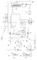
- Fig. 1 shows a refrigerant circuit diagram of an air conditioner according to the embodiment of the present invention
- Fig. 2 shows a control flow diagram for an oil-return operation thereof.
- a multi--type air conditioner 1 in which a plurality of indoor units 3A and 3B are connected in parallel to a single outdoor unit 2 is described as the air conditioner 1.
- the plurality of the indoor units 3A and 3B are connected in parallel with each other via splitters 6 between a gas-side pipe 4 and a liquid-side pipe 5 that lead out from the outdoor unit 2.
- the outdoor unit 2 is provided with an inverter-driven compressor 10 that compresses refrigerant, an oil separator 11 that separates lubricant from refrigerant gas, a four-way switch valve 12 that switches the circulation direction of the refrigerant, an outdoor heat exchanger 13 that performs heat exchange between the refrigerant and outdoor air, a supercooling coil 14 integrally formed with the outdoor heat exchanger 13, a heating expansion valve (EEVH) 15, a receiver 16 for storing liquid refrigerant, a supercooling heat exchanger 17 that causes supercooling of the liquid refrigerant, a supercooling expansion valve (EEVSC) 18 that controls the amount of refrigerant that is diverted to the supercooling heat exchanger 17, an accumulator 19 that separates a liquid component from refrigerant gas taken into the compressor 10 so that only a gas component is taken into the compressor 10 side, a gas-side actuating valve 20, and a liquid-side actuating valve 21.
- an inverter-driven compressor 10 that compress
- the individual equipment described above on the outdoor unit 2 side is connected in a known manner via a refrigerant pipe 22, thus forming an outdoor-side refrigerant circuit 23.
- the outdoor units 2 is provided with an outdoor fan 24 that blows the outdoor air toward the outdoor heat exchanger 13.
- an oil-return circuit 25 for returning the lubricant separated from the discharged refrigerant gas in the oil separator 11 to the compressor 10 side by a predetermined amount at a time is provided between the oil separator 11 and an intake pipe of the compressor 10.
- the gas-side pipe 4 and the liquid-side pipe 5 are the refrigerant pipes that are connected to the gas-side actuating valve 20 and the liquid-side actuating valve 21 of the outdoor unit 2, and the pipe length thereof is set at the time of onsite installation in accordance with the distance between the outdoor unit 2 and the plurality of the indoor units 3A and 3B to be connected thereto.
- An appropriate number of the splitters 6 are provided at intermediate positions in the gas-side pipe 4 and the liquid-side pipe 5, and an appropriate number of the indoor units 3A and 3B are connected via the splitters 6. Accordingly, the refrigerating cycle (refrigerant circuit) 7 is formed as a single closed system.
- the indoor units 3A and 3B are provided with indoor heat exchangers 30 in which the indoor air undergoes heat exchange with the refrigerant to be supplied for air conditioning of room interiors, a cooling expansion valves (EEVC) 31, indoor fans 32 that circulate the indoor air via the indoor heat exchangers 30, and indoor controllers 33, and the indoor units 3A and 3B are connected to the splitters 6 via gas-side splitting pipes 4A and 4B and liquid-side splitting pipes 5A and 5B on the indoor side.
- EEVC cooling expansion valves
- the cooling operation of the multi-type air conditioner 1 described above is performed as follows.
- the oil separator 11 the lubricant contained in the refrigerant is separated from high-temperature, high-pressure refrigerant gas compressed and discharged from the compressor 10.
- the refrigerant gas is circulated by the four-way switching valve 12 to the outdoor heat exchanger 13 side and is condensed into liquid through heat exchange at the outdoor heat exchanger 13 with the outdoor air blown thereon by the outdoor fan 24.
- This liquid refrigerant is further cooled by the supercooling coil 14, subsequently passes through the heating expansion valve 15, and is temporarily stored in the receiver 16.
- the liquid refrigerant whose circulated amount is adjusted at the receiver 16, is diverted from the liquid refrigerant pipe in the process of flowing at the liquid refrigerant pipe side via the supercooling heat exchanger 17, and the liquid refrigerant undergoes heat exchange with adiabatically expanded refrigerant at the supercooling expansion valve (EEVSC) 18 to be supercooled.
- EVSC supercooling expansion valve
- This liquid refrigerant is guided to the liquid-side pipe 5 from the outdoor unit 2 via the liquid-side actuating valve 21, and, furthermore, the liquid refrigerant that has been guided to the liquid-side pipe 5 is diverted to the liquid-side splitting pipes 5A and 5B of the individual indoor units 3A and 3B via the splitters 6.
- the liquid refrigerant diverted to the liquid-side splitting pipes 5A and 5B flows into the individual indoor units 3A and 3B, is adiabatically expanded at the cooling expansion valves (EEVC) 31, and flows into the indoor heat exchangers 30 as gas-liquid two-phase flows.
- EEVC cooling expansion valves
- the indoor heat exchangers 30 heat exchange occurs between the indoor air circulated by the indoor fans 32 and the refrigerant, thus cooling the indoor air to be supplied for cooling the room interiors.
- the refrigerant is gasified, reaches the splitters 6 via gas-side splitting pipes 4A and 4B, and is combined with the refrigerant gas from other indoor units at the gas-side pipe 4.
- the refrigerant gas combined at the gas-side pipe 4 returns to the outdoor unit 2 again, combines with the refrigerant gas from the supercooling heat exchanger 17 via the gas-side actuating valve 20 and the four-way switching valve 12, and is subsequently introduced to the accumulator 19.
- the liquid component contained in the refrigerant gas is separated and only the gas component is taken into the compressor 10. This refrigerant is compressed again in the compressor 10, and the cooling operation is performed by repeating the above-described cycle.
- the heating operation is performed as follows.
- the high-temperature, high-pressure refrigerant gas that has been compressed by the compressor 10 and then discharged therefrom is circulated to the gas-side actuating valve 20 side via the four-way switching valve 12 after the lubricant contained in the refrigerant is separated at the oil separator 11.
- the refrigerant is guided out from the outdoor unit 2 via the gas-side actuating valve 20 and the gas-side pipe 4, and, furthermore, it is introduced to the plurality of the indoor units 3A and 3B via the splitters 6 and the gas-side splitting pipes 4A and 4B on the indoor side.
- the liquid refrigerant that has been condensed at the indoor heat exchangers 30 reaches the splitters 6 via the cooling expansion valves (EEVC) 31 and the liquid-side splitting pipes 5A and 5B and is returned to the outdoor unit 2 via the liquid-side pipe 5 after being combined with the refrigerant from the other indoor units.
- EEVC cooling expansion valves
- the degree of opening of the cooling expansion valves (EEVC) 31 is controlled by the indoor controllers 33 so that the refrigerant outlet temperature (hereinafter, referred to as heat-exchange outlet temperature) or refrigerant supercooling at the indoor heat exchangers 30, which function as condensers, reach control target values.
- the refrigerant that has returned to the outdoor unit 2 reaches the supercooling heat exchanger 17 via the liquid-side actuating valve 21 and, after being supercooled, as in the case of cooling, flows into the receiver 16 so that the circulated amount of the refrigerant is adjusted by temporarily being stored therein.
- This liquid refrigerant is supplied to the heating expansion valve (EEVH) 15 to be adiabatically expanded and subsequently flows into the outdoor heat exchanger 13 via the supercooling coil 14.
- the outdoor heat exchanger 13 heat exchange is performed between the refrigerant and the outdoor air that is blown thereon by the outdoor fan 24, and the refrigerant is evaporated and gasified by absorbing heat from the outdoor air.
- the refrigerant from the outdoor heat exchanger 13 is combined with the refrigerant gas from the supercooling heat exchanger 17 via the four-way switching valve 12 and is then introduced to the accumulator 19.
- the liquid component contained in the refrigerant gas is separated at the accumulator 19 and only the gas component is taken into the compressor 10 to be compressed again at the compressor 10.
- the heating operation is performed by repeating the above-described cycle.
- the length of the refrigerant pipes between the outdoor unit 2 and the indoor units 3A and 3B becomes very long. Because of this, the lubricant that has flowed out along with the refrigerant from the compressor 10 to the refrigerating cycle (refrigerant circuit) 7 side tends to remain in the refrigerating cycle (refrigerant circuit) 7, and a situation tends to occur in which the amount of lubricant at the compressor 10 side becomes insufficient.
- the oil-return operation is performed when predetermined oil-return conditions are satisfied by continuing the operation of the air conditioner 1.
- the oil-return-operation control portion 40 sets the refrigerating cycle (refrigerant circuit) 7 to the cooling cycle described above via the four-way switch valve 12, during which the rotational speed of the compressor 10 is increased to a set rotational speed, and the degree of opening of the cooling expansion valves (EEVC) 31 of all indoor units 3A and 3B is increased to a set degree of opening via the indoor controllers 33, thereby executing this oil-return operation.
- the refrigerating cycle refrigerant circuit
- the oil-return conditions are one or both of
- the oil-return conditions (A) and (B) have been known in the related art.
- the outdoor air temperature is monitored, and continuation of a state in which the outdoor air temperature detected by an outdoor air temperature sensor 44 is higher than a set value (for example, 49°C) over a predetermined time (for example, 3 minutes) is added as a condition (C), and high-outdoor-air-temperature oil-return operation means 43 is provided, which performs a forced oil-return operation via the oil-return-operation control portion 40 when this condition (C) is satisfied.
- the oil-return operation is prohibited for a certain period of time (for example, three hours).
- the oil-return operation is prohibited for the certain period of time, the oil-return operation is prohibited even if the state in which the outdoor air temperature is high continues and the outdoor air temperature equal to or above the set value is re-detected, or even if the above-described oil-return conditions (A), (B) are satisfied.
- the prohibition of the oil-return operation for the certain period of time is removed, and the oil-return operation is performed when the above-described conditions (A), (B) are satisfied.
- this embodiment when the oil-return operation is performed because the above-described three conditions (A), (B), and (C) are satisfied, the degree of opening of the cooling expansion valves (EEVC) 31 is increased to the set degree of opening by the indoor controllers 33 and the rotational speed of the compressor 10 is increased to the set rotational speed; and, in addition, this embodiment is provided with high-pressure-protection-value changing means 46 that is activated on the basis of detection values of a high-pressure sensor 45 and that increases a high-pressure-protection value of a high-pressure pressure switch (not shown) for high-pressure protection that causes abnormal halt of the compressor 10 by a predetermined value (for example, 3.7 MPa is changed to 3.8 MPa).
- a predetermined value for example, 3.7 MPa is changed to 3.8 MPa
- Fig. 2 shows a control flow diagram of the oil-return operation described above.
- the oil-return operation is performed when the operating-time accumulating means 41, the outflowed-lubricant-amount calculating means 42, and the high-outdoor-air-temperature oil-return operation means 43 detect, during normal cooling/heating operation of the air conditioner 1, that any of the following three conditions is satisfied,
- the oil-return operation is terminated when known operation-terminating conditions set in advance are satisfied.
- "success" or "failure" of the oil-return operation is determined (for example, the case in which intake superheating SH of the compressor 10 continues to be at or below a predetermined value over a predetermined period of time is determined to be success), and in the case of "failure", a retry-oil-return operation is performed under the predetermined conditions.
- this embodiment affords the following effects and advantages.
- the oil-return-operation control portion 40 sets the refrigerating cycle (refrigerant circuit) 7 to the cooling cycle, increases the high-pressure-protection value of the high-pressure pressure switch, which is activated on the basis of the detection value from the high-pressure sensor 45, by the predetermined value, increases the degree of opening of the cooling expansion valves (EEVC) 31 of the indoor units 3A and 3B to the set degree of opening via the indoor controllers 33, and, furthermore, increases the rotational speed (drive frequency) of the compressor 10 to the set rotational speed, thus starting the oil-return operation.
- EEVC cooling expansion valves
- the oil-return operation is also performed when a state in which the outdoor air temperature is higher than the set value continues for the predetermined period of time, in addition to when the continuous operation time of the air conditioner 1 or the cumulative operation time thereof reaches the predetermined amount of time and the amount of outflowed lubricant (oil rise level) from the compressor 10 reaches the predetermined amount, and the oil-return operation is prohibited for the predetermined period of time after performing this forced oil-retuning operation via the high-outdoor-air-temperature oil-return operation means 43.
- the forced oil-return operation can be performed in advance before the temperature increases further and the oil-return operation becomes difficult due to high-pressure shutdown, and, by doing so, in the certain period of time that follows, the operation of the air conditioner 1 can be continued without having to perform the oil-return operation.
- the prohibition of the oil-return operation for the certain period of time is removed when the outdoor air temperature is below the set value
- the prohibition of the oil-return operation for the certain period of time is removed because the outdoor air temperature is below the set value
- the normal oil-return operation is restored, and thus, the oil-return operation is performed when the predetermined oil-return conditions (A) to (C) are satisfied. Therefore, it is possible to cope with an environment in which the outdoor air temperature is high while maintaining the oil-return-operation function based on the conventional oil-return conditions (A) and (B), and it is possible to expand the regions where the air conditioner 1 can be installed.
- the high-pressure-protection value of the high-pressure pressure switch is increased by the predetermined value via the high-pressure-protection-value changing means 46. Accordingly, when the oil-return operation is performed by increasing the rotational speed of the compressor 10, although the high pressure easily increases, the high-pressure pressure switch is activated, and thus the compressor 10 may come to an abnormal halt due high-pressure shutdown, the abnormal stop of the compressor 10 due to the high-pressure shutdown can be prevented by increasing the high-pressure-protection value by the predetermined value via the high-pressure-protection-value changing means 46 and the forced oil-return operation can be performed.
- the oil-return operation can be performed reliably even if the air conditioner 1 is installed in an environment in which the outdoor air temperature is high, and the reliability of the air conditioner 1 can be increased by avoiding a situation in which the lubricant in the compressor 10 runs out.
- the present invention is not limited to the above-described embodiment, and appropriate alterations are possible within a range that does not depart from the spirit thereof.
- the high-pressure-protection value of the high-pressure pressure switch is increased by the predetermined value via the high-pressure-protection-value changing means 46 regardless of the oil-return conditions (A) to (C) under which the oil-return operation is performed; however, the oil-return operation may be performed by changing the high-pressure-protection value of the high-pressure pressure switch only when performing the forced oil-return operation via the high-outdoor-air-temperature oil-return operation means 43, during which the high pressure increases particularly easily.
Landscapes
- Engineering & Computer Science (AREA)
- Physics & Mathematics (AREA)
- Mechanical Engineering (AREA)
- Thermal Sciences (AREA)
- General Engineering & Computer Science (AREA)
- Chemical & Material Sciences (AREA)
- Analytical Chemistry (AREA)
- Power Engineering (AREA)
- Air Conditioning Control Device (AREA)
Applications Claiming Priority (2)
| Application Number | Priority Date | Filing Date | Title |
|---|---|---|---|
| JP2010013050A JP5484930B2 (ja) | 2010-01-25 | 2010-01-25 | 空気調和機 |
| PCT/JP2011/050214 WO2011089938A1 (fr) | 2010-01-25 | 2011-01-07 | Appareil de conditionnement d'air |
Publications (4)
| Publication Number | Publication Date |
|---|---|
| EP2530407A1 true EP2530407A1 (fr) | 2012-12-05 |
| EP2530407A4 EP2530407A4 (fr) | 2014-01-08 |
| EP2530407B1 EP2530407B1 (fr) | 2017-11-01 |
| EP2530407B8 EP2530407B8 (fr) | 2017-12-06 |
Family
ID=44306741
Family Applications (1)
| Application Number | Title | Priority Date | Filing Date |
|---|---|---|---|
| EP11734545.4A Active EP2530407B8 (fr) | 2010-01-25 | 2011-01-07 | Appareil de conditionnement d'air |
Country Status (7)
| Country | Link |
|---|---|
| US (1) | US9285148B2 (fr) |
| EP (1) | EP2530407B8 (fr) |
| JP (1) | JP5484930B2 (fr) |
| KR (1) | KR101297972B1 (fr) |
| CN (1) | CN102575884B (fr) |
| ES (1) | ES2655533T3 (fr) |
| WO (1) | WO2011089938A1 (fr) |
Cited By (1)
| Publication number | Priority date | Publication date | Assignee | Title |
|---|---|---|---|---|
| CN109539649A (zh) * | 2018-12-04 | 2019-03-29 | 珠海格力电器股份有限公司 | 机组回油控制方法、系统及多联机 |
Families Citing this family (41)
| Publication number | Priority date | Publication date | Assignee | Title |
|---|---|---|---|---|
| JP2013044512A (ja) * | 2011-08-26 | 2013-03-04 | Yanmar Co Ltd | 空調システム |
| JP2013155964A (ja) | 2012-01-31 | 2013-08-15 | Fujitsu General Ltd | 空気調和装置 |
| EP2924366B1 (fr) * | 2012-11-21 | 2020-06-17 | Mitsubishi Electric Corporation | Dispositif de climatisation |
| CN104180563B (zh) | 2013-05-27 | 2017-06-20 | 珠海格力电器股份有限公司 | 多联机系统制热时的回油方法 |
| JP6230931B2 (ja) * | 2014-02-20 | 2017-11-15 | 三菱重工サーマルシステムズ株式会社 | マルチ形空気調和機 |
| JP6327558B2 (ja) * | 2014-06-04 | 2018-05-23 | パナソニックIpマネジメント株式会社 | 空気調和装置 |
| JP6334320B2 (ja) * | 2014-08-22 | 2018-05-30 | 株式会社Nttファシリティーズ | 蒸気圧縮式冷凍サイクル |
| JP6509013B2 (ja) * | 2015-04-01 | 2019-05-08 | 日立ジョンソンコントロールズ空調株式会社 | 冷凍装置及び冷凍機ユニット |
| CN104764167B (zh) * | 2015-04-21 | 2018-05-01 | 珠海格力电器股份有限公司 | 变频空调压缩机的回油控制方法 |
| JP6459800B2 (ja) * | 2015-06-26 | 2019-01-30 | 株式会社富士通ゼネラル | 空気調和装置 |
| JP6458666B2 (ja) * | 2015-06-30 | 2019-01-30 | 株式会社富士通ゼネラル | 空気調和装置 |
| WO2017006452A1 (fr) * | 2015-07-08 | 2017-01-12 | 三菱電機株式会社 | Dispositif de conditionnement d'air |
| CN105066537B (zh) * | 2015-07-15 | 2017-09-29 | 宁波奥克斯电气股份有限公司 | 多联机制热回油控制方法 |
| WO2017183068A1 (fr) * | 2016-04-18 | 2017-10-26 | 三菱電機株式会社 | Dispositif à cycle frigorifique |
| JP6615056B2 (ja) * | 2016-06-28 | 2019-12-04 | 三菱電機株式会社 | 空気調和機 |
| IT201600099499A1 (it) * | 2016-10-04 | 2018-04-04 | Carel Ind Spa | Dispositivo per il rilevamento di una condizione di lubrificazione ottimizzabile in un compressore di un impianto frigorifero, gruppo compressore che lo comprende e metodo per il rilevamento di una condizione di lubrificazione ottimizzabile in un compressore di un impianto frigorifero |
| CN106524593B (zh) * | 2016-11-08 | 2019-04-30 | 广东美的暖通设备有限公司 | 风冷热泵空调机组及其压缩机的回油控制方法和装置 |
| JP6540666B2 (ja) * | 2016-11-24 | 2019-07-10 | ダイキン工業株式会社 | 冷凍装置 |
| JP6847216B2 (ja) * | 2017-06-23 | 2021-03-24 | 三菱電機株式会社 | 冷凍サイクル装置 |
| CN107490129B (zh) * | 2017-08-02 | 2020-10-20 | 青岛海尔空调电子有限公司 | 一种设备控制的方法及装置 |
| CN107575939B (zh) * | 2017-09-07 | 2019-10-25 | 珠海格力电器股份有限公司 | 多联机系统及其控制方法 |
| CN108613434A (zh) * | 2018-04-12 | 2018-10-02 | 珠海格力电器股份有限公司 | 空调的回油控制方法及装置 |
| JP7199032B2 (ja) * | 2018-07-30 | 2023-01-05 | パナソニックIpマネジメント株式会社 | 空気調和装置 |
| CN109489210B (zh) * | 2018-10-15 | 2020-12-29 | 珠海格力电器股份有限公司 | 多联机系统回油控制方法、装置、回油控制设备及空调 |
| CN109357440B (zh) * | 2018-10-26 | 2019-11-05 | 宁波奥克斯电气股份有限公司 | 一种多联机制热回油控制方法及多联机空调器 |
| CN109539630B (zh) * | 2018-11-13 | 2020-05-29 | 青岛海尔空调器有限总公司 | 用于压缩制冷或制热装置的压缩机回油方法 |
| CN109539632B (zh) * | 2018-11-28 | 2019-10-01 | 珠海格力电器股份有限公司 | 一种回油控制方法、装置、存储介质及空调 |
| JP7417368B2 (ja) * | 2019-05-27 | 2024-01-18 | シャープ株式会社 | 空気調和機 |
| CN110608501B (zh) * | 2019-09-04 | 2022-03-11 | 青岛海尔空调电子有限公司 | 用于空调器的回油控制方法及空调器 |
| JP6828790B1 (ja) * | 2019-10-31 | 2021-02-10 | ダイキン工業株式会社 | 冷凍装置 |
| CN113587499B (zh) * | 2020-04-14 | 2022-10-28 | 青岛海尔空调器有限总公司 | 空调系统的冷冻机油循环量控制方法 |
| CN111457544B (zh) * | 2020-04-20 | 2021-10-15 | 宁波奥克斯电气股份有限公司 | 一种空调运行方法及空调器 |
| CN113719963B (zh) * | 2020-05-25 | 2022-12-27 | 青岛海尔空调电子有限公司 | 多联机系统的回油控制方法 |
| CN115727510A (zh) * | 2021-08-31 | 2023-03-03 | 广东美的制冷设备有限公司 | 空调器回油的控制方法、控制装置、空调器 |
| US11874033B2 (en) * | 2021-09-07 | 2024-01-16 | Hill Phoenix, Inc. | Increasing a flow rate of oil into a compressor of a refrigeration assembly |
| CN114322267B (zh) * | 2022-01-04 | 2024-01-26 | 广东美的制冷设备有限公司 | 空调器的控制方法、空调器及存储介质 |
| CN115585531B (zh) * | 2022-10-12 | 2025-10-24 | 青岛海尔空调器有限总公司 | 用于控制空调回油的方法、装置及空调 |
| CN115654671B (zh) * | 2022-11-18 | 2024-07-16 | 青岛海尔空调器有限总公司 | 空调器的控制方法、控制装置及空调器 |
| CN115978738B (zh) * | 2022-12-13 | 2024-05-10 | 珠海格力电器股份有限公司 | 回油控制方法以及空调系统 |
| CN118208859B (zh) * | 2022-12-15 | 2025-09-02 | 合肥华凌股份有限公司 | 制冷系统及其缺油判断方法 |
| CN116678090B (zh) * | 2023-05-16 | 2025-07-04 | 宁波奥克斯电气有限公司 | 一种空调器及其控制方法、装置和可读存储介质 |
Family Cites Families (17)
| Publication number | Priority date | Publication date | Assignee | Title |
|---|---|---|---|---|
| US4893284A (en) | 1988-05-27 | 1990-01-09 | General Electric Company | Calibration of phased array ultrasound probe |
| JPH0772654B2 (ja) | 1989-08-09 | 1995-08-02 | ダイキン工業株式会社 | 空気調和装置の運転制御装置 |
| US5551249A (en) * | 1992-10-05 | 1996-09-03 | Van Steenburgh, Jr.; Leon R. | Liquid chiller with bypass valves |
| JP3418287B2 (ja) * | 1995-12-20 | 2003-06-16 | 東芝キヤリア株式会社 | マルチ式空気調和機の油回収制御装置 |
| JP2966786B2 (ja) | 1995-12-29 | 1999-10-25 | 三洋電機株式会社 | 空気調和機 |
| JPH09318166A (ja) | 1996-05-30 | 1997-12-12 | Mitsubishi Heavy Ind Ltd | 冷凍装置 |
| JP4270765B2 (ja) | 2001-02-16 | 2009-06-03 | 三洋電機株式会社 | 空気調和装置 |
| ATE470114T1 (de) | 2002-04-08 | 2010-06-15 | Daikin Ind Ltd | Kühlvorrichtung |
| KR100468916B1 (ko) * | 2002-05-01 | 2005-02-02 | 삼성전자주식회사 | 공기 조화기 및 그 제어 방법 |
| JP4176679B2 (ja) | 2004-06-14 | 2008-11-05 | 三菱重工業株式会社 | 空気調和装置の制御方法及びその制御装置、並びに空気調和装置 |
| US7104076B2 (en) * | 2004-06-24 | 2006-09-12 | Carrier Corporation | Lubricant return schemes for use in refrigerant cycle |
| KR100575693B1 (ko) | 2004-10-18 | 2006-05-03 | 엘지전자 주식회사 | 보조압축회로를 구비한 공기조화기 |
| JP2007057126A (ja) | 2005-08-23 | 2007-03-08 | Matsushita Electric Ind Co Ltd | 冷蔵庫 |
| JP2007139276A (ja) | 2005-11-16 | 2007-06-07 | Sanden Corp | 冷却システム |
| US8359873B2 (en) | 2006-08-22 | 2013-01-29 | Carrier Corporation | Oil return in refrigerant system |
| KR101552618B1 (ko) | 2009-02-25 | 2015-09-11 | 엘지전자 주식회사 | 공기 조화기 |
| US8234877B2 (en) * | 2009-07-08 | 2012-08-07 | Trane International Inc. | Compressor discharge valve providing freeze and charge migration protection |
-
2010
- 2010-01-25 JP JP2010013050A patent/JP5484930B2/ja not_active Expired - Fee Related
-
2011
- 2011-01-07 US US13/499,834 patent/US9285148B2/en active Active
- 2011-01-07 EP EP11734545.4A patent/EP2530407B8/fr active Active
- 2011-01-07 ES ES11734545.4T patent/ES2655533T3/es active Active
- 2011-01-07 WO PCT/JP2011/050214 patent/WO2011089938A1/fr not_active Ceased
- 2011-01-07 CN CN201180004250.7A patent/CN102575884B/zh not_active Expired - Fee Related
- 2011-01-07 KR KR1020127009251A patent/KR101297972B1/ko active Active
Cited By (1)
| Publication number | Priority date | Publication date | Assignee | Title |
|---|---|---|---|---|
| CN109539649A (zh) * | 2018-12-04 | 2019-03-29 | 珠海格力电器股份有限公司 | 机组回油控制方法、系统及多联机 |
Also Published As
| Publication number | Publication date |
|---|---|
| EP2530407B1 (fr) | 2017-11-01 |
| JP5484930B2 (ja) | 2014-05-07 |
| JP2011149659A (ja) | 2011-08-04 |
| US9285148B2 (en) | 2016-03-15 |
| EP2530407A4 (fr) | 2014-01-08 |
| CN102575884A (zh) | 2012-07-11 |
| CN102575884B (zh) | 2015-05-13 |
| WO2011089938A1 (fr) | 2011-07-28 |
| EP2530407B8 (fr) | 2017-12-06 |
| KR20120065398A (ko) | 2012-06-20 |
| KR101297972B1 (ko) | 2013-08-19 |
| US20120192581A1 (en) | 2012-08-02 |
| ES2655533T3 (es) | 2018-02-20 |
Similar Documents
| Publication | Publication Date | Title |
|---|---|---|
| EP2530407B1 (fr) | Appareil de conditionnement d'air | |
| JP6230931B2 (ja) | マルチ形空気調和機 | |
| JP5125124B2 (ja) | 冷凍装置 | |
| US10088206B2 (en) | Air-conditioning apparatus | |
| JP6403887B2 (ja) | 冷凍サイクル装置、遠隔監視システム、遠隔監視装置および異常判定方法 | |
| JP5563609B2 (ja) | 冷媒システム及びその制御方法 | |
| EP2256435A1 (fr) | Climatiseur multi-type et son procédé d'opération de retour d'huile | |
| EP3252402B1 (fr) | Pompe à chaleur | |
| KR102330339B1 (ko) | 멀티형 공기조화기 및 그의 제어방법 | |
| EP3136010B1 (fr) | Dispositif de conditionnement d'air | |
| EP3040655A1 (fr) | Climatiseur | |
| JP7676101B2 (ja) | 空調機制御装置、これを備える空調機、空調機の制御方法および空調機の制御プログラム | |
| JP5192883B2 (ja) | マルチ形空気調和機 | |
| JP5308205B2 (ja) | 空気調和機 | |
| JP2009243842A (ja) | マルチ型空気調和機および室外機の運転方法 | |
| JP2014085078A (ja) | 空気調和装置 | |
| JP2011242097A (ja) | 冷凍装置 | |
| KR102390900B1 (ko) | 멀티형 공기조화기 및 그의 제어방법 | |
| JP5578914B2 (ja) | マルチ形空気調和装置 | |
| KR102250983B1 (ko) | 멀티형 공기조화기 | |
| JP6057512B2 (ja) | クランクケースヒータを備えた空気調和機 | |
| EP3073213A1 (fr) | Appareil, programme et procédé de commande de système de climatisation et un tel système | |
| JP2008190767A (ja) | 冷凍装置 | |
| CN121576681A (zh) | 空调器控制方法、系统、空调器及计算机程序产品 |
Legal Events
| Date | Code | Title | Description |
|---|---|---|---|
| PUAI | Public reference made under article 153(3) epc to a published international application that has entered the european phase |
Free format text: ORIGINAL CODE: 0009012 |
|
| 17P | Request for examination filed |
Effective date: 20120411 |
|
| AK | Designated contracting states |
Kind code of ref document: A1 Designated state(s): AL AT BE BG CH CY CZ DE DK EE ES FI FR GB GR HR HU IE IS IT LI LT LU LV MC MK MT NL NO PL PT RO RS SE SI SK SM TR |
|
| DAX | Request for extension of the european patent (deleted) | ||
| A4 | Supplementary search report drawn up and despatched |
Effective date: 20131206 |
|
| RIC1 | Information provided on ipc code assigned before grant |
Ipc: F25B 31/00 20060101ALI20131202BHEP Ipc: F24F 11/02 20060101ALI20131202BHEP Ipc: F25B 43/02 20060101ALI20131202BHEP Ipc: F25B 1/00 20060101AFI20131202BHEP |
|
| GRAP | Despatch of communication of intention to grant a patent |
Free format text: ORIGINAL CODE: EPIDOSNIGR1 |
|
| INTG | Intention to grant announced |
Effective date: 20170718 |
|
| GRAS | Grant fee paid |
Free format text: ORIGINAL CODE: EPIDOSNIGR3 |
|
| GRAA | (expected) grant |
Free format text: ORIGINAL CODE: 0009210 |
|
| AK | Designated contracting states |
Kind code of ref document: B1 Designated state(s): AL AT BE BG CH CY CZ DE DK EE ES FI FR GB GR HR HU IE IS IT LI LT LU LV MC MK MT NL NO PL PT RO RS SE SI SK SM TR |
|
| REG | Reference to a national code |
Ref country code: GB Ref legal event code: FG4D |
|
| REG | Reference to a national code |
Ref country code: CH Ref legal event code: EP Ref country code: AT Ref legal event code: REF Ref document number: 942440 Country of ref document: AT Kind code of ref document: T Effective date: 20171115 |
|
| RAP2 | Party data changed (patent owner data changed or rights of a patent transferred) |
Owner name: MITSUBISHI HEAVY INDUSTRIES THERMAL SYSTEMS, LTD. |
|
| REG | Reference to a national code |
Ref country code: IE Ref legal event code: FG4D |
|
| REG | Reference to a national code |
Ref country code: DE Ref legal event code: R096 Ref document number: 602011042903 Country of ref document: DE |
|
| REG | Reference to a national code |
Ref country code: FR Ref legal event code: PLFP Year of fee payment: 8 |
|
| REG | Reference to a national code |
Ref country code: ES Ref legal event code: FG2A Ref document number: 2655533 Country of ref document: ES Kind code of ref document: T3 Effective date: 20180220 |
|
| REG | Reference to a national code |
Ref country code: NL Ref legal event code: MP Effective date: 20171101 |
|
| REG | Reference to a national code |
Ref country code: LT Ref legal event code: MG4D |
|
| REG | Reference to a national code |
Ref country code: AT Ref legal event code: MK05 Ref document number: 942440 Country of ref document: AT Kind code of ref document: T Effective date: 20171101 |
|
| PG25 | Lapsed in a contracting state [announced via postgrant information from national office to epo] |
Ref country code: NL Free format text: LAPSE BECAUSE OF FAILURE TO SUBMIT A TRANSLATION OF THE DESCRIPTION OR TO PAY THE FEE WITHIN THE PRESCRIBED TIME-LIMIT Effective date: 20171101 Ref country code: LT Free format text: LAPSE BECAUSE OF FAILURE TO SUBMIT A TRANSLATION OF THE DESCRIPTION OR TO PAY THE FEE WITHIN THE PRESCRIBED TIME-LIMIT Effective date: 20171101 Ref country code: NO Free format text: LAPSE BECAUSE OF FAILURE TO SUBMIT A TRANSLATION OF THE DESCRIPTION OR TO PAY THE FEE WITHIN THE PRESCRIBED TIME-LIMIT Effective date: 20180201 Ref country code: SE Free format text: LAPSE BECAUSE OF FAILURE TO SUBMIT A TRANSLATION OF THE DESCRIPTION OR TO PAY THE FEE WITHIN THE PRESCRIBED TIME-LIMIT Effective date: 20171101 Ref country code: FI Free format text: LAPSE BECAUSE OF FAILURE TO SUBMIT A TRANSLATION OF THE DESCRIPTION OR TO PAY THE FEE WITHIN THE PRESCRIBED TIME-LIMIT Effective date: 20171101 |
|
| PG25 | Lapsed in a contracting state [announced via postgrant information from national office to epo] |
Ref country code: IS Free format text: LAPSE BECAUSE OF FAILURE TO SUBMIT A TRANSLATION OF THE DESCRIPTION OR TO PAY THE FEE WITHIN THE PRESCRIBED TIME-LIMIT Effective date: 20180301 Ref country code: HR Free format text: LAPSE BECAUSE OF FAILURE TO SUBMIT A TRANSLATION OF THE DESCRIPTION OR TO PAY THE FEE WITHIN THE PRESCRIBED TIME-LIMIT Effective date: 20171101 Ref country code: BG Free format text: LAPSE BECAUSE OF FAILURE TO SUBMIT A TRANSLATION OF THE DESCRIPTION OR TO PAY THE FEE WITHIN THE PRESCRIBED TIME-LIMIT Effective date: 20180201 Ref country code: GR Free format text: LAPSE BECAUSE OF FAILURE TO SUBMIT A TRANSLATION OF THE DESCRIPTION OR TO PAY THE FEE WITHIN THE PRESCRIBED TIME-LIMIT Effective date: 20180202 Ref country code: LV Free format text: LAPSE BECAUSE OF FAILURE TO SUBMIT A TRANSLATION OF THE DESCRIPTION OR TO PAY THE FEE WITHIN THE PRESCRIBED TIME-LIMIT Effective date: 20171101 Ref country code: AT Free format text: LAPSE BECAUSE OF FAILURE TO SUBMIT A TRANSLATION OF THE DESCRIPTION OR TO PAY THE FEE WITHIN THE PRESCRIBED TIME-LIMIT Effective date: 20171101 Ref country code: RS Free format text: LAPSE BECAUSE OF FAILURE TO SUBMIT A TRANSLATION OF THE DESCRIPTION OR TO PAY THE FEE WITHIN THE PRESCRIBED TIME-LIMIT Effective date: 20171101 |
|
| PG25 | Lapsed in a contracting state [announced via postgrant information from national office to epo] |
Ref country code: CY Free format text: LAPSE BECAUSE OF FAILURE TO SUBMIT A TRANSLATION OF THE DESCRIPTION OR TO PAY THE FEE WITHIN THE PRESCRIBED TIME-LIMIT Effective date: 20171101 Ref country code: EE Free format text: LAPSE BECAUSE OF FAILURE TO SUBMIT A TRANSLATION OF THE DESCRIPTION OR TO PAY THE FEE WITHIN THE PRESCRIBED TIME-LIMIT Effective date: 20171101 Ref country code: SK Free format text: LAPSE BECAUSE OF FAILURE TO SUBMIT A TRANSLATION OF THE DESCRIPTION OR TO PAY THE FEE WITHIN THE PRESCRIBED TIME-LIMIT Effective date: 20171101 Ref country code: DK Free format text: LAPSE BECAUSE OF FAILURE TO SUBMIT A TRANSLATION OF THE DESCRIPTION OR TO PAY THE FEE WITHIN THE PRESCRIBED TIME-LIMIT Effective date: 20171101 Ref country code: CZ Free format text: LAPSE BECAUSE OF FAILURE TO SUBMIT A TRANSLATION OF THE DESCRIPTION OR TO PAY THE FEE WITHIN THE PRESCRIBED TIME-LIMIT Effective date: 20171101 |
|
| REG | Reference to a national code |
Ref country code: DE Ref legal event code: R097 Ref document number: 602011042903 Country of ref document: DE |
|
| PG25 | Lapsed in a contracting state [announced via postgrant information from national office to epo] |
Ref country code: PL Free format text: LAPSE BECAUSE OF FAILURE TO SUBMIT A TRANSLATION OF THE DESCRIPTION OR TO PAY THE FEE WITHIN THE PRESCRIBED TIME-LIMIT Effective date: 20171101 Ref country code: SM Free format text: LAPSE BECAUSE OF FAILURE TO SUBMIT A TRANSLATION OF THE DESCRIPTION OR TO PAY THE FEE WITHIN THE PRESCRIBED TIME-LIMIT Effective date: 20171101 Ref country code: RO Free format text: LAPSE BECAUSE OF FAILURE TO SUBMIT A TRANSLATION OF THE DESCRIPTION OR TO PAY THE FEE WITHIN THE PRESCRIBED TIME-LIMIT Effective date: 20171101 |
|
| REG | Reference to a national code |
Ref country code: CH Ref legal event code: PL |
|
| PLBE | No opposition filed within time limit |
Free format text: ORIGINAL CODE: 0009261 |
|
| STAA | Information on the status of an ep patent application or granted ep patent |
Free format text: STATUS: NO OPPOSITION FILED WITHIN TIME LIMIT |
|
| 26N | No opposition filed |
Effective date: 20180802 |
|
| PG25 | Lapsed in a contracting state [announced via postgrant information from national office to epo] |
Ref country code: LU Free format text: LAPSE BECAUSE OF NON-PAYMENT OF DUE FEES Effective date: 20180107 |
|
| REG | Reference to a national code |
Ref country code: IE Ref legal event code: MM4A |
|
| REG | Reference to a national code |
Ref country code: BE Ref legal event code: MM Effective date: 20180131 |
|
| PG25 | Lapsed in a contracting state [announced via postgrant information from national office to epo] |
Ref country code: SI Free format text: LAPSE BECAUSE OF FAILURE TO SUBMIT A TRANSLATION OF THE DESCRIPTION OR TO PAY THE FEE WITHIN THE PRESCRIBED TIME-LIMIT Effective date: 20171101 Ref country code: CH Free format text: LAPSE BECAUSE OF NON-PAYMENT OF DUE FEES Effective date: 20180131 Ref country code: BE Free format text: LAPSE BECAUSE OF NON-PAYMENT OF DUE FEES Effective date: 20180131 Ref country code: LI Free format text: LAPSE BECAUSE OF NON-PAYMENT OF DUE FEES Effective date: 20180131 |
|
| PG25 | Lapsed in a contracting state [announced via postgrant information from national office to epo] |
Ref country code: IE Free format text: LAPSE BECAUSE OF NON-PAYMENT OF DUE FEES Effective date: 20180107 |
|
| PG25 | Lapsed in a contracting state [announced via postgrant information from national office to epo] |
Ref country code: MC Free format text: LAPSE BECAUSE OF FAILURE TO SUBMIT A TRANSLATION OF THE DESCRIPTION OR TO PAY THE FEE WITHIN THE PRESCRIBED TIME-LIMIT Effective date: 20171101 |
|
| PG25 | Lapsed in a contracting state [announced via postgrant information from national office to epo] |
Ref country code: MT Free format text: LAPSE BECAUSE OF NON-PAYMENT OF DUE FEES Effective date: 20180107 |
|
| PG25 | Lapsed in a contracting state [announced via postgrant information from national office to epo] |
Ref country code: TR Free format text: LAPSE BECAUSE OF FAILURE TO SUBMIT A TRANSLATION OF THE DESCRIPTION OR TO PAY THE FEE WITHIN THE PRESCRIBED TIME-LIMIT Effective date: 20171101 |
|
| PG25 | Lapsed in a contracting state [announced via postgrant information from national office to epo] |
Ref country code: HU Free format text: LAPSE BECAUSE OF FAILURE TO SUBMIT A TRANSLATION OF THE DESCRIPTION OR TO PAY THE FEE WITHIN THE PRESCRIBED TIME-LIMIT; INVALID AB INITIO Effective date: 20110107 Ref country code: PT Free format text: LAPSE BECAUSE OF FAILURE TO SUBMIT A TRANSLATION OF THE DESCRIPTION OR TO PAY THE FEE WITHIN THE PRESCRIBED TIME-LIMIT Effective date: 20171101 |
|
| PG25 | Lapsed in a contracting state [announced via postgrant information from national office to epo] |
Ref country code: MK Free format text: LAPSE BECAUSE OF NON-PAYMENT OF DUE FEES Effective date: 20171101 |
|
| PG25 | Lapsed in a contracting state [announced via postgrant information from national office to epo] |
Ref country code: AL Free format text: LAPSE BECAUSE OF FAILURE TO SUBMIT A TRANSLATION OF THE DESCRIPTION OR TO PAY THE FEE WITHIN THE PRESCRIBED TIME-LIMIT Effective date: 20171101 |
|
| PGFP | Annual fee paid to national office [announced via postgrant information from national office to epo] |
Ref country code: GB Payment date: 20251127 Year of fee payment: 16 |
|
| PGFP | Annual fee paid to national office [announced via postgrant information from national office to epo] |
Ref country code: FR Payment date: 20251128 Year of fee payment: 16 |
|
| PGFP | Annual fee paid to national office [announced via postgrant information from national office to epo] |
Ref country code: ES Payment date: 20260203 Year of fee payment: 16 |
|
| PGFP | Annual fee paid to national office [announced via postgrant information from national office to epo] |
Ref country code: DE Payment date: 20251203 Year of fee payment: 16 |
|
| PGFP | Annual fee paid to national office [announced via postgrant information from national office to epo] |
Ref country code: IT Payment date: 20251219 Year of fee payment: 16 |