EP2530422A2 - Dispositif et procédé destinés à éviter les dépôts sur un échangeur thermique - Google Patents
Dispositif et procédé destinés à éviter les dépôts sur un échangeur thermique Download PDFInfo
- Publication number
- EP2530422A2 EP2530422A2 EP12169053A EP12169053A EP2530422A2 EP 2530422 A2 EP2530422 A2 EP 2530422A2 EP 12169053 A EP12169053 A EP 12169053A EP 12169053 A EP12169053 A EP 12169053A EP 2530422 A2 EP2530422 A2 EP 2530422A2
- Authority
- EP
- European Patent Office
- Prior art keywords
- heat exchanger
- air
- heat
- flow channel
- flue gas
- Prior art date
- Legal status (The legal status is an assumption and is not a legal conclusion. Google has not performed a legal analysis and makes no representation as to the accuracy of the status listed.)
- Withdrawn
Links
- 238000000034 method Methods 0.000 title claims abstract description 10
- 238000002485 combustion reaction Methods 0.000 claims abstract description 70
- UGFAIRIUMAVXCW-UHFFFAOYSA-N Carbon monoxide Chemical compound [O+]#[C-] UGFAIRIUMAVXCW-UHFFFAOYSA-N 0.000 claims abstract description 57
- 239000003546 flue gas Substances 0.000 claims abstract description 56
- 239000000919 ceramic Substances 0.000 claims abstract description 5
- 229910052751 metal Inorganic materials 0.000 claims abstract description 5
- 239000002184 metal Substances 0.000 claims abstract description 5
- 239000003570 air Substances 0.000 claims description 84
- 239000012080 ambient air Substances 0.000 claims description 6
- 230000009969 flowable effect Effects 0.000 abstract 1
- 230000005855 radiation Effects 0.000 description 15
- 239000002245 particle Substances 0.000 description 12
- 239000000446 fuel Substances 0.000 description 11
- 238000010438 heat treatment Methods 0.000 description 8
- 239000000463 material Substances 0.000 description 8
- 241000711969 Chandipura virus Species 0.000 description 7
- 238000004804 winding Methods 0.000 description 4
- 238000011161 development Methods 0.000 description 3
- 230000018109 developmental process Effects 0.000 description 3
- 238000003860 storage Methods 0.000 description 3
- 239000002028 Biomass Substances 0.000 description 2
- 239000003344 environmental pollutant Substances 0.000 description 2
- 239000007789 gas Substances 0.000 description 2
- 238000004519 manufacturing process Methods 0.000 description 2
- 239000008188 pellet Substances 0.000 description 2
- 231100000719 pollutant Toxicity 0.000 description 2
- 239000004449 solid propellant Substances 0.000 description 2
- 239000000443 aerosol Substances 0.000 description 1
- 238000000137 annealing Methods 0.000 description 1
- 229910002091 carbon monoxide Inorganic materials 0.000 description 1
- 230000007797 corrosion Effects 0.000 description 1
- 238000005260 corrosion Methods 0.000 description 1
- 230000008021 deposition Effects 0.000 description 1
- 230000005611 electricity Effects 0.000 description 1
- 230000005670 electromagnetic radiation Effects 0.000 description 1
- 229910052500 inorganic mineral Inorganic materials 0.000 description 1
- 239000010954 inorganic particle Substances 0.000 description 1
- 238000005304 joining Methods 0.000 description 1
- 239000011707 mineral Substances 0.000 description 1
- 239000000779 smoke Substances 0.000 description 1
- 239000007787 solid Substances 0.000 description 1
- 238000005382 thermal cycling Methods 0.000 description 1
- 230000008646 thermal stress Effects 0.000 description 1
Images

Classifications
-
- F—MECHANICAL ENGINEERING; LIGHTING; HEATING; WEAPONS; BLASTING
- F28—HEAT EXCHANGE IN GENERAL
- F28F—DETAILS OF HEAT-EXCHANGE AND HEAT-TRANSFER APPARATUS, OF GENERAL APPLICATION
- F28F19/00—Preventing the formation of deposits or corrosion, e.g. by using filters or scrapers
-
- F—MECHANICAL ENGINEERING; LIGHTING; HEATING; WEAPONS; BLASTING
- F28—HEAT EXCHANGE IN GENERAL
- F28D—HEAT-EXCHANGE APPARATUS, NOT PROVIDED FOR IN ANOTHER SUBCLASS, IN WHICH THE HEAT-EXCHANGE MEDIA DO NOT COME INTO DIRECT CONTACT
- F28D21/00—Heat-exchange apparatus not covered by any of the groups F28D1/00 - F28D20/00
- F28D21/0001—Recuperative heat exchangers
- F28D21/0003—Recuperative heat exchangers the heat being recuperated from exhaust gases
- F28D21/001—Recuperative heat exchangers the heat being recuperated from exhaust gases for thermal power plants or industrial processes
Definitions
- the invention relates to a device for preventing deposits on a heat exchanger, according to the preamble of claim 1, and a method in which the device according to the invention is used according to claim 9.
- Combustion heating systems with heat engines that convert thermal energy into mechanical energy are known in the art.
- the heat engines usually designed as external internal combustion engines (eg a Stirling engine) are used, for example, for (micro) cogeneration applications (CHP plants).
- Such an external combustion engine can also be operated with renewable energies.
- Biomass combustion eg pellet combustion plays an important role here.
- At least one heat exchanger is provided, which is flowed around in a flow channel of a hot flue gas stream, whereby a heat transfer from the flue gas stream to the heat exchanger.
- convection a transport of heated particles from a heat source (for example a burner) to a heat sink (for example a heat exchanger).
- the heat transfer performance to the heat exchanger is very high.
- Thermal conduction occurs due to a temperature difference which, in particular due to lattice vibrations, leads to heat flow within a material without transport of particles. It can not be done through a vacuum, since there are no material structures or lattice structures.
- Heat radiation flame radiation and solid state radiation
- electromagnetic radiation is electromagnetic radiation that allows heat transfer by air or vacuum. It only requires the possibility of propagation of electromagnetic waves.
- FIG. 1 For this purpose, a heat exchanger between the heat exchanger and the flue gas stream is arranged ("interposed"). The heat transfer from the flue gas stream to the heat exchanger then takes place exclusively via heat conduction and heat radiation. There is no direct contact between the flue gas and the heat exchanger, since the flue gas flow is separated from the heat exchanger, whereby the pollution (particle deposition) and corrosion on the heat exchanger can be prevented.
- the effective surface area of the heat exchanger is too small for heat transfer, the heat transfer efficiency may be too low due to the lack of convective heat transfer rate. This has the consequence that the efficiency is low, resulting from the amount of heat transferred per fuel unit.
- the invention is therefore an object of the invention to overcome the disadvantages of the prior art, and to provide a device and a method for preventing deposits on a heat exchanger, which allows improved heat transfer from the flue gas stream to an indirectly heated heat exchanger, so that the efficiency despite compact dimensions is at the level of direct heating of a heat exchanger without deposits.
- the invention should allow a high and permanent heat transfer in a small size, cost little, as well as ecologically and easily be implemented.
- the solution should be suitable to be used in a combined heat and power plant, and their efficiency should be high.
- the invention relates to a device for preventing deposits on a heat exchanger, which is arranged in a main flow channel. Through the main flow channel, a flue gas stream is conductive.
- a heat exchanger between the heat exchanger and the main flow channel is arranged so that the flue gas flow has no contact with the heat exchanger. It is inventively provided that the heat exchanger has at least one cavity which can be flowed through by an air flow.
- heat exchanger located in a main flow channel is meant a heat exchanger that is wholly or partially disposed in the main flow channel or constitutes a boundary of the flow channel, for example by the heat exchanger forming a portion of a flow channel wall.
- flue gas and exhaust gas are used synonymously here and below.
- the heat exchanger may for example be flat or include the heat exchanger. In this case, a further cavity between the heat exchanger and the heat exchanger can be formed.
- Such heat exchangers can also be referred to as a radiation shield.
- the space required for the heat exchanger is small, whereby the size of the unit consisting of heat exchangers, Main flow channel and heat exchanger compared to conventional solutions shrinks. This contributes significantly to low costs and is also ecologically sensible. Furthermore, the solution is also suitable to be used in a combined heat and power plant.
- the flue gas stream can be generated for example in a combustion device with burner and combustion chamber. In this usually fuel and combustion air is introduced and burned. The combustion flame can reach into the main flow channel with the heat exchanger, but this need not necessarily. Depending on the operating state of the combustion device, the flue gas flow then carries a variable number of particles, which can be deposited on a heat exchanger in a combustion device without heat exchangers. This is prevented with the heat exchanger according to the invention, resulting in a permanent and consistently high indirect heat transferability from the flue gas stream to the heat exchanger.
- the heat exchanger allows heat transfer by radiation from the flue gas stream to the heat exchanger. It is possible to heat the heat exchanger by means of the flue gas stream at least partially, in particular its surface directed into the main flow channel, to the annealing. In such a heating deposits are burned on the heat exchanger and thus cleaned, or this remains clean for very long periods of operation, since no form deposits on its surface. This advantage is particularly important in the case of the use of renewable and / or solid fuels, which can cause a very high number of particles in the flue gas stream. For maximum heat transfer, the heat exchanger should be made of a high emissivity material.
- heat transfer by convection is achieved by passing the air flow through the cavity of the invention. Ideally, this is done in countercurrent to the flue gas stream.
- the air flow is adapted to absorb heat from the heat exchanger and then deliver it to the heat exchanger or arranged closer to the heat exchanger components. This increases the amount of heat transferred from the flue gas to the heat exchanger compared to pure heat transfer by radiation. Accordingly, a high efficiency is achieved. Since the air flow is essentially particle-free, it does not lead to deposits at the heat exchanger. The air flow in the tip is heated approximately to the temperature of the flue gas flow.
- a development of the invention provides that the heat exchanger and the heat exchanger are arranged such that a secondary flow channel is formed between them, which can be flowed through by the air flow.
- the cavity of the heat exchanger is arranged in the flow direction of the air flow in front of the secondary flow channel.
- An air stream guided through the cavity first heats up here by heat transfer from the heat exchanger and then gives off heat to the heat exchanger in the secondary flow channel.
- turbulence in the secondary flow channel here comes to a strong convection and thereby to a high heat transfer to the heat exchanger.
- An additional embodiment of the invention provides that the heat exchanger and the secondary flow channel form a preheating device, whereby the air flow can be heated.
- This heated air flow can be used in various ways to increase the efficiency of heat transfer or an incinerator.
- the air flow can be circulated, for example, in a closed circuit, whereby no continuous initial heating of the air flow must occur.
- a preheated air stream can also be used as combustion air, whereby the efficiency of a combustion plant can be increased.
- a burner and a combustion chamber are flow-connected to the main flow channel. These are suitable for generating a flue gas stream.
- the heat exchanger has at least one single-channel pipe spiral (pipe spiral) or shell structure.
- a pipe spiral can be inexpensively produced by a winding.
- the individual winding may be connected by a joining process, or it is, for example, a clamping element is provided, which holds the windings kraftbeaufschlagt together.
- Such a pipe spiral has a large surface area for the transfer of heat.
- sharp kinks are not present, whereby the flow resistance for the air flow is low. For its production, accordingly, little energy is needed.
- a shell structure can be produced with other production methods, in particular by prototyping and forming. Therefore, hereby also heat exchangers with complex designs can be realized. If the aligned to the main flow channel side is integrally formed, it is also not to columns due to thermal stresses, so that the flue gas flow is reliably and easily separated from the heat exchanger.
- the heat exchanger consists essentially of metal or ceramic. These materials have a high emissivity, so that a high heat transfer is achieved in a compact design. In addition, these materials are robust against high thermal cycling and can be heated to very high temperatures, whereby a high thermal radiation is achieved.
- the device is of paramount importance if the heat exchanger is part of a combined heat and power plant, by means of which thermal energy can be converted into mechanical energy.
- Such CHP plants often have very long operating times per year. Even small advantages in the efficiency then have a significant impact on the fuel demand.
- Such CHP systems are often designed as external combustion engines, whose best known representative is the Stirling engine.
- the heat exchanger of a Stirling engine is also called Stirling heater head. If these CHP plants are operated as combined heat and power plants, electricity is generated by the generated mechanical energy. By the According to the invention increase in the efficiency, the cost of such a combined heat and power plant amortize much faster.
- the invention further provides a method in which a device according to the invention described above is used, wherein a flue gas stream is passed through the main flow channel, and wherein the cavity is traversed by an air flow.
- a device for preventing deposits on a heat exchanger is used, in which the heat exchanger is arranged in a main flow channel.
- a heat exchanger between the heat exchanger and the main flow channel is arranged so that the flue gas flow has no contact with the heat exchanger.
- the heat exchanger has the cavity, which is flowed through by the air flow.
- the space required for the heat exchanger space is small, whereby the size of the unit consisting of heat exchanger, main flow channel and heat exchanger is small. This contributes significantly to low costs and is ecologically sensible. Furthermore, the solution is also suitable to be used in a combined heat and power plant.
- the flue gas stream can be generated for example in a combustion device with burner and combustion chamber. In this usually fuel and combustion air is introduced and burned the fuel. The combustion flame can reach into the main flow channel with the heat exchanger, but this need not necessarily. Depending on the operating state of the combustion device and the fuel, the flue gas stream then carries a variable number of particles with it, which can be deposited on a heat exchanger without separating heat exchanger. According to the invention this is prevented with the heat exchanger, resulting in a permanent and consistently high indirect heat transferability from the flue gas stream to the heat exchanger.
- the heat exchanger allows heat transfer by radiation from the flue gas stream to the heat exchanger. It is possible to heat the heat exchanger by means of the flue gas stream until glowing. In such a heating deposits are burned on the heat exchanger and thus cleaned, or this remains clean for very long periods of operation. This advantage is particularly important when using renewable and solid fuels, which can cause a very high number of particles in the flue gas flow.
- the heat exchanger should be made of a material with a high emissivity.
- heat transfer is achieved by convection by the air flow is passed through the cavity according to the invention in the heat exchanger, ideally in countercurrent to the flue gas stream.
- the air stream is adapted to receive heat from the heat exchanger and subsequently to discharge to the heat exchanger or to components (e.g., heat fins on the heat exchanger surface) closer to the heat exchanger. This increases the amount of heat transferred from the flue gas to the heat exchanger as compared to a pure heat transfer by radiation. Accordingly, a high efficiency is achieved.
- the air flow is taken from the ambient air on the input side of the heat exchanger and passed on the output side in a combustion chamber of the flue gas-generating combustion device.
- the heated air is supplied to the combustion, whereby the efficiency of the combustion chamber belonging to the combustion system is improved.
- Another variant provides that the air flow is removed on the input side of the heat exchanger from an air reservoir and on its output side again into this into it, wherein air is passed from the air reservoir into the combustion chamber and the air reservoir is supplied to compensate for ambient air.
- Such an air accumulator compensates for the different air requirements of the heat exchanger and the combustion chamber.
- preheating the air flow increases the efficiency of the heat exchanger and by the preheating of the combustion air, the combustion chamber.
- the storage is designed so that heated air at any time of operation is not released into the environment.
- the heated air from the air reservoir can be guided into a second combustion chamber of the combustion chamber, where an afterburning of the flue gas stream takes place.
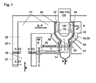
- Fig. 1 shows a heat exchanger 10, which is arranged in a main flow channel 11.
- a flue gas stream R can be passed.
- a heat exchanger 30 is disposed between the heat exchanger 10 and the main flow channel 11, in particular includes / surrounds the heat exchanger 30, the heat exchanger 10.
- the flue gas flow R thus has no contact with the heat exchanger 10.
- the heat exchanger 30 has a cavity 31, of an air flow L can be flowed through.
- the heat exchanger 30 has a single-channel pipe spiral 35 with an input side 33 and an output side 34, the interior of which forms the cavity 31.
- such a heat exchanger 30 made of metal or ceramic.
- the heat exchanger 30 and the heat exchanger 10 are arranged such that a secondary flow channel 32 is formed between them, which is also flowed through by the air flow L.
- the cavity 31 of the heat exchanger 30 is arranged in the flow direction of the air flow L in front of the secondary flow channel 32. In this way, the heat exchanger 30 and the secondary flow channel 32 form a preheating device 50, whereby the air flow L can be heated.
- the heat exchanger 10 is part of a combined heat and power plant 100, by means of which thermal energy is converted into mechanical energy.
- the heat exchanger 10 belongs to an external combustion engine 110 or to a Stirling engine 120.
- the heat exchanger 10 is a so-called Stirling heater head 121.
- a combustion device 19 is arranged in the flow direction of the flue gas stream R in front of the heat exchanger 10. This consists of a burner and two Combustion chambers 20, in particular a primary combustion chamber 21 and a secondary combustion chamber 22.
- the primary combustion chamber 21 is fluidly connected to the secondary combustion chamber 22 and the latter with the main flow channel 11.
- combustion air V is introduced.
- the primary combustion air V1 introduced into the primary combustion chamber 21 is combusted with fuel B.
- an afterburning of the flowing out of the primary combustion chamber 21 flue gas R is made.
- the flue gas flow R in the flow channel 11 contains a high number of particles P until afterburning in the secondary combustion chamber 22 is stable.
- the flue gas flow R with the particles P then flows in the main flow passage 11 past the heat exchanger 30. It transfers heat to the heat exchanger 30 and then leaves the main flow passage 11 cooled in the environment.
- the air flow L generated by a flow generator 40, flows in countercurrent to the flue gas flow R from the inlet side 33 of the heat exchanger 30 through the cavity 31 formed by the tube spiral 35 to the outlet side 34 of the heat exchanger 30.
- the air flow L hereby absorbs heat from the heat exchanger 30 and already gives off some of the heat on the heat exchanger 10 facing side of the heat exchanger 30 back to the heat exchanger 10.
- the air flow L is then deflected into the secondary flow channel 32, where it flows around the heat exchanger 10 in cocurrent to the flue gas flow R. At the latter, the air flow then by heat radiation and convection heat. At the same time, it also absorbs heat from the heat exchanger 30 in the secondary flow channel 32. After leaving the secondary flow channel 32, the incompletely cooled air stream L is then guided into an air reservoir 60, from which the air for the air stream L is also removed. In addition, air S from the air reservoir 60 in the combustion chamber 20, in particular in the secondary combustion chamber 22, passed and the air reservoir 60 is supplied to compensate for ambient air U.
- Fig. 2 describes a heat exchanger 10, which is arranged in a main flow channel 11. By the latter, a flue gas stream R can be passed.
- the flue gas flow R thus has no direct contact with the heat exchanger 10.
- the heat exchanger 30 has a cavity 31 which is traversed by an air flow L.
- the heat exchanger 30 has a single-channel shell structure 36 with an input side 33 and an output side 34, the interior of which forms the cavity 31.
- such a heat exchanger 30 made of metal or ceramic.
- the heat exchanger 30 and the heat exchanger 10 are arranged such that a secondary flow channel 32 is formed between them, which is also flowed through by the air flow L.
- the cavity 31 of the heat exchanger 30 is arranged in the flow direction of the air flow L in front of the secondary flow channel 32. In this way, the heat exchanger 30 and the secondary flow channel 32 form a preheating device 50, whereby the air flow L can be heated.
- the heat exchanger 10 is a so-called Stirling heater head 121.
- the flue gas flow R with particles P flows in the main flow passage 11 past the heat exchanger 30. In so doing, it transfers heat to the heat exchanger 30 and then leaves the main flow passage 11 at a low temperature into the environment.
- the air flow L generated by a flow generator 40, flows in countercurrent to the flue gas flow R from the inlet side 33 of the heat exchanger 30 through the cavity 31 formed by the shell structure 36 to the outlet side 34 of the heat exchanger 30.
- the air flow absorbs heat from the heat exchanger 30 and already gives off some of the heat on the heat exchanger 10 facing side of the heat exchanger 30 to the heat exchanger 10 from.
- the air flow L is then deflected into the secondary flow channel 32, where it flows around the heat exchanger 10 in cocurrent to the flue gas flow R. On the latter he then gives off heat radiation and convection heat. At the same time, it also absorbs heat from the heat exchanger 30 in the secondary flow channel 32. Subsequently, the air flow L leaves the secondary flow channel 32.
Landscapes
- Engineering & Computer Science (AREA)
- Physics & Mathematics (AREA)
- Thermal Sciences (AREA)
- Mechanical Engineering (AREA)
- General Engineering & Computer Science (AREA)
- Air Supply (AREA)
- Heat-Exchange Devices With Radiators And Conduit Assemblies (AREA)
Applications Claiming Priority (1)
| Application Number | Priority Date | Filing Date | Title |
|---|---|---|---|
| DE201110108633 DE102011108633A1 (de) | 2011-05-30 | 2011-05-30 | Vorrichtung und Verfahren zur Vermeidung von Ablagerungen an einem Wärmetauscher |
Publications (2)
| Publication Number | Publication Date |
|---|---|
| EP2530422A2 true EP2530422A2 (fr) | 2012-12-05 |
| EP2530422A3 EP2530422A3 (fr) | 2014-04-09 |
Family
ID=46168224
Family Applications (1)
| Application Number | Title | Priority Date | Filing Date |
|---|---|---|---|
| EP12169053.1A Withdrawn EP2530422A3 (fr) | 2011-05-30 | 2012-05-23 | Dispositif et procédé destinés à éviter les dépôts sur un échangeur thermique |
Country Status (2)
| Country | Link |
|---|---|
| EP (1) | EP2530422A3 (fr) |
| DE (1) | DE102011108633A1 (fr) |
Cited By (1)
| Publication number | Priority date | Publication date | Assignee | Title |
|---|---|---|---|---|
| CN115615231A (zh) * | 2022-12-16 | 2023-01-17 | 天津市创举科技股份有限公司 | 一种中压蒸汽代替管式炉加热富油工艺及设备 |
Citations (1)
| Publication number | Priority date | Publication date | Assignee | Title |
|---|---|---|---|---|
| DE102006001299A1 (de) | 2006-01-11 | 2007-07-12 | Eckhart Weber | Holzpellet-Blockheizkraftwerk mit Stirlingmotor in Brennwerttechnik |
Family Cites Families (7)
| Publication number | Priority date | Publication date | Assignee | Title |
|---|---|---|---|---|
| US4151217A (en) * | 1972-07-04 | 1979-04-24 | Mitsubishi Jukogyo Kabushiki Kaisha | Method of cooling cracked gases of low boiling hydrocarbons |
| US4246887A (en) * | 1978-01-12 | 1981-01-27 | Christiansen Marion W | Heat recovery and solar assist heating system |
| GB8906200D0 (en) * | 1989-03-17 | 1989-05-04 | Cubit Ltd | Heat exchanger |
| AU662456B2 (en) * | 1993-01-07 | 1995-08-31 | Arthur Maurice Meredith | A thermal oil heater |
| US7216696B2 (en) * | 1999-09-23 | 2007-05-15 | Ferraro Joseph C | External flue heat exchangers |
| EP1809967B1 (fr) * | 2004-11-12 | 2013-01-09 | Zenex Technologies Ltd. | Utilisation d'un echangeur thermique avec une chaudiere a condensation |
| AT507235B1 (de) * | 2008-08-22 | 2012-09-15 | Vaillant Group Austria Gmbh | Vorrichtung und verfahren zur erkennung der alterung einer abgasführung, eines abgassammlers und/oder eines wärmetauschergehäuses aus kunststoff |
-
2011
- 2011-05-30 DE DE201110108633 patent/DE102011108633A1/de not_active Withdrawn
-
2012
- 2012-05-23 EP EP12169053.1A patent/EP2530422A3/fr not_active Withdrawn
Patent Citations (1)
| Publication number | Priority date | Publication date | Assignee | Title |
|---|---|---|---|---|
| DE102006001299A1 (de) | 2006-01-11 | 2007-07-12 | Eckhart Weber | Holzpellet-Blockheizkraftwerk mit Stirlingmotor in Brennwerttechnik |
Cited By (1)
| Publication number | Priority date | Publication date | Assignee | Title |
|---|---|---|---|---|
| CN115615231A (zh) * | 2022-12-16 | 2023-01-17 | 天津市创举科技股份有限公司 | 一种中压蒸汽代替管式炉加热富油工艺及设备 |
Also Published As
| Publication number | Publication date |
|---|---|
| EP2530422A3 (fr) | 2014-04-09 |
| DE102011108633A1 (de) | 2012-12-06 |
Similar Documents
| Publication | Publication Date | Title |
|---|---|---|
| DE112011104756B4 (de) | Anlage zur berührungslosen Schlammtrocknung mittels Rauchgasabwärme | |
| DE9007521U1 (de) | Vorrichtung zur Erzeugung elektrischer und Heizenergie | |
| AT402848B (de) | Fluidheizer | |
| WO2010086085A2 (fr) | Procédé pour faire fonctionner une installation d'oxydation et installation d'oxydation | |
| EP0952406A2 (fr) | Groupe de chauffage et de puissance | |
| DE102010020277A1 (de) | Verfahren zur Reduzierung von Stickoxiden im Rauchgas einer Verbrennungsanlage sowie Verbrennungsanlage | |
| DE102016218438A1 (de) | Verfahren und Anordnung zur Wärmeenergierückgewinnung in Anlagen umfassend wenigstens einen Reformer | |
| DE4227985A1 (de) | Gasturbinen-anordnung mit einem combustor vom rohrbuendel-brennkammer-typ | |
| EP2530422A2 (fr) | Dispositif et procédé destinés à éviter les dépôts sur un échangeur thermique | |
| DE102016202259B4 (de) | Hochtemperatur-Elektrolysevorrichtung sowie Verfahren zum Durchführen einer Hochtemperatur-Elektrolyse | |
| DE3222787A1 (de) | Verbundkreislauf-kraftwerksanlage mit umlauffliessbett-waermeuebertragung | |
| DE102011082205A1 (de) | Verfahren zum Betrieb eines regenerativ beheizten Industrieofens und regenerativ geheizter Industrieofen | |
| DE102004034688A1 (de) | Einrichtung zur Erzeugung von elektrischer Energie aus thermischer Energie, insbesondere Luftheiz- und Konvektionsofen | |
| WO2013178446A1 (fr) | Procédé de préchauffage d'air pour des chaudières à vapeur et dispositif pour mettre en œuvre ce procédé | |
| DE102006047342B3 (de) | Doppelwandiger Stahlschornstein zur Gewinnung elektrischer Energie | |
| DE2450249B1 (de) | Abwaermeverwertung fuer Durchlaufbackoefen | |
| DE102010063839A1 (de) | Verfahren zum Betreiben eines Ofens in einer Anlage zur Metallverarbeitung und Anlage zur Metallverarbeitung | |
| DE2922083A1 (de) | Feuerungsanlage | |
| DE102008007756A1 (de) | Elektrostatischer Feinstaubfilter für Rauchgasreinigung | |
| DE102016014793A1 (de) | Verfahren und Vorrichtung zur Vermeidung des Feinstaubs und Rückgewinnung der Abgaswärme von Holz-Pelett-Heizungsanlagen | |
| EP3193082B1 (fr) | Procede et dispositif de production de vapeur surchauffee au moyen de chaleur produite dans la chaudiere d'une installation de combustion | |
| WO2009046757A1 (fr) | Procédé et appareil d'exploitation de la chaleur résiduelle d'un four annulaire à anodes | |
| DE102015213862B3 (de) | Verbrennungskraftwerksanlage mit verbesserter Effizienz durch korrosionsbeständige Wärmeübertrager | |
| DE102009038556A1 (de) | Verfahren und Vorrichtung zum Beheizen eines Wärmetauschers einer Wärmekraftmaschine sowie Verbrennungsheizanlage mit Wärmekraftmaschine | |
| DE102011102811A1 (de) | Verfahren zur Reduzierung von Brennstoffablagerungen an einem Wärmetauscher |
Legal Events
| Date | Code | Title | Description |
|---|---|---|---|
| PUAI | Public reference made under article 153(3) epc to a published international application that has entered the european phase |
Free format text: ORIGINAL CODE: 0009012 |
|
| AK | Designated contracting states |
Kind code of ref document: A2 Designated state(s): AL AT BE BG CH CY CZ DE DK EE ES FI FR GB GR HR HU IE IS IT LI LT LU LV MC MK MT NL NO PL PT RO RS SE SI SK SM TR |
|
| AX | Request for extension of the european patent |
Extension state: BA ME |
|
| PUAL | Search report despatched |
Free format text: ORIGINAL CODE: 0009013 |
|
| AK | Designated contracting states |
Kind code of ref document: A3 Designated state(s): AL AT BE BG CH CY CZ DE DK EE ES FI FR GB GR HR HU IE IS IT LI LT LU LV MC MK MT NL NO PL PT RO RS SE SI SK SM TR |
|
| AX | Request for extension of the european patent |
Extension state: BA ME |
|
| RIC1 | Information provided on ipc code assigned before grant |
Ipc: F28F 19/00 20060101AFI20140306BHEP Ipc: F28D 21/00 20060101ALI20140306BHEP |
|
| 17P | Request for examination filed |
Effective date: 20141009 |
|
| RBV | Designated contracting states (corrected) |
Designated state(s): AL AT BE BG CH CY CZ DE DK EE ES FI FR GB GR HR HU IE IS IT LI LT LU LV MC MK MT NL NO PL PT RO RS SE SI SK SM TR |
|
| 17Q | First examination report despatched |
Effective date: 20141212 |
|
| GRAP | Despatch of communication of intention to grant a patent |
Free format text: ORIGINAL CODE: EPIDOSNIGR1 |
|
| INTG | Intention to grant announced |
Effective date: 20150722 |
|
| STAA | Information on the status of an ep patent application or granted ep patent |
Free format text: STATUS: THE APPLICATION IS DEEMED TO BE WITHDRAWN |
|
| 18D | Application deemed to be withdrawn |
Effective date: 20151202 |