EP2530447A2 - Dispositif de mesure de balourd - Google Patents
Dispositif de mesure de balourd Download PDFInfo
- Publication number
- EP2530447A2 EP2530447A2 EP12181726A EP12181726A EP2530447A2 EP 2530447 A2 EP2530447 A2 EP 2530447A2 EP 12181726 A EP12181726 A EP 12181726A EP 12181726 A EP12181726 A EP 12181726A EP 2530447 A2 EP2530447 A2 EP 2530447A2
- Authority
- EP
- European Patent Office
- Prior art keywords
- spindle
- holder
- rotation
- force
- elements
- Prior art date
- Legal status (The legal status is an assumption and is not a legal conclusion. Google has not performed a legal analysis and makes no representation as to the accuracy of the status listed.)
- Withdrawn
Links
- 230000008878 coupling Effects 0.000 claims abstract description 25
- 238000010168 coupling process Methods 0.000 claims abstract description 25
- 238000005859 coupling reaction Methods 0.000 claims abstract description 25
- 230000003287 optical effect Effects 0.000 claims description 15
- 239000000725 suspension Substances 0.000 claims description 15
- 125000006850 spacer group Chemical group 0.000 claims description 13
- 230000000712 assembly Effects 0.000 claims description 8
- 238000000429 assembly Methods 0.000 claims description 8
- 238000006073 displacement reaction Methods 0.000 claims description 6
- 238000005304 joining Methods 0.000 claims description 2
- 238000005259 measurement Methods 0.000 description 19
- 230000008901 benefit Effects 0.000 description 5
- 238000006243 chemical reaction Methods 0.000 description 5
- 238000010276 construction Methods 0.000 description 3
- 230000001154 acute effect Effects 0.000 description 2
- 238000002788 crimping Methods 0.000 description 2
- 230000001419 dependent effect Effects 0.000 description 2
- 238000004519 manufacturing process Methods 0.000 description 2
- 239000000463 material Substances 0.000 description 2
- 238000000034 method Methods 0.000 description 2
- 230000009467 reduction Effects 0.000 description 2
- 230000008439 repair process Effects 0.000 description 2
- 230000009471 action Effects 0.000 description 1
- 239000011248 coating agent Substances 0.000 description 1
- 238000000576 coating method Methods 0.000 description 1
- 230000007547 defect Effects 0.000 description 1
- 230000002950 deficient Effects 0.000 description 1
- 238000001514 detection method Methods 0.000 description 1
- 238000005553 drilling Methods 0.000 description 1
- 230000006872 improvement Effects 0.000 description 1
- 238000009434 installation Methods 0.000 description 1
- 238000003754 machining Methods 0.000 description 1
- 230000013011 mating Effects 0.000 description 1
- 238000003801 milling Methods 0.000 description 1
- 230000010355 oscillation Effects 0.000 description 1
- 230000000737 periodic effect Effects 0.000 description 1
- 230000002093 peripheral effect Effects 0.000 description 1
- 230000008569 process Effects 0.000 description 1
- 230000011218 segmentation Effects 0.000 description 1
Images


Classifications
-
- G—PHYSICS
- G01—MEASURING; TESTING
- G01M—TESTING STATIC OR DYNAMIC BALANCE OF MACHINES OR STRUCTURES; TESTING OF STRUCTURES OR APPARATUS, NOT OTHERWISE PROVIDED FOR
- G01M1/00—Testing static or dynamic balance of machines or structures
- G01M1/14—Determining imbalance
-
- G—PHYSICS
- G01—MEASURING; TESTING
- G01M—TESTING STATIC OR DYNAMIC BALANCE OF MACHINES OR STRUCTURES; TESTING OF STRUCTURES OR APPARATUS, NOT OTHERWISE PROVIDED FOR
- G01M1/00—Testing static or dynamic balance of machines or structures
- G01M1/02—Details of balancing machines or devices
- G01M1/04—Adaptation of bearing support assemblies for receiving the body to be tested
-
- G—PHYSICS
- G01—MEASURING; TESTING
- G01D—MEASURING NOT SPECIALLY ADAPTED FOR A SPECIFIC VARIABLE; ARRANGEMENTS FOR MEASURING TWO OR MORE VARIABLES NOT COVERED IN A SINGLE OTHER SUBCLASS; TARIFF METERING APPARATUS; MEASURING OR TESTING NOT OTHERWISE PROVIDED FOR
- G01D5/00—Mechanical means for transferring the output of a sensing member; Means for converting the output of a sensing member to another variable where the form or nature of the sensing member does not constrain the means for converting; Transducers not specially adapted for a specific variable
- G01D5/26—Mechanical means for transferring the output of a sensing member; Means for converting the output of a sensing member to another variable where the form or nature of the sensing member does not constrain the means for converting; Transducers not specially adapted for a specific variable characterised by optical transfer means, i.e. using infrared, visible, or ultraviolet light
- G01D5/32—Mechanical means for transferring the output of a sensing member; Means for converting the output of a sensing member to another variable where the form or nature of the sensing member does not constrain the means for converting; Transducers not specially adapted for a specific variable characterised by optical transfer means, i.e. using infrared, visible, or ultraviolet light with attenuation or whole or partial obturation of beams of light
- G01D5/34—Mechanical means for transferring the output of a sensing member; Means for converting the output of a sensing member to another variable where the form or nature of the sensing member does not constrain the means for converting; Transducers not specially adapted for a specific variable characterised by optical transfer means, i.e. using infrared, visible, or ultraviolet light with attenuation or whole or partial obturation of beams of light the beams of light being detected by photocells
- G01D5/347—Mechanical means for transferring the output of a sensing member; Means for converting the output of a sensing member to another variable where the form or nature of the sensing member does not constrain the means for converting; Transducers not specially adapted for a specific variable characterised by optical transfer means, i.e. using infrared, visible, or ultraviolet light with attenuation or whole or partial obturation of beams of light the beams of light being detected by photocells using displacement encoding scales
- G01D5/34707—Scales; Discs, e.g. fixation, fabrication, compensation
-
- G—PHYSICS
- G01—MEASURING; TESTING
- G01M—TESTING STATIC OR DYNAMIC BALANCE OF MACHINES OR STRUCTURES; TESTING OF STRUCTURES OR APPARATUS, NOT OTHERWISE PROVIDED FOR
- G01M1/00—Testing static or dynamic balance of machines or structures
- G01M1/02—Details of balancing machines or devices
- G01M1/06—Adaptation of drive assemblies for receiving the body to be tested
Definitions
- the invention relates to a device for measuring the rotational imbalance of an object, for example a machine element or a tool holder.
- the spindle of modern rotating machine tools operate at very high speeds of 20,000 rpm. and above. At these speeds high centrifugal forces occur even at low imbalance, which not only burden the spindle bearings of the machine tool, but also worsen the service life of the tool as well as the machining result.
- the tool holder is therefore usually on balancing machines, as for example WO 00/45 983 are known, balanced with or without inserted tool before use in the machine tool.
- the improvement according to the invention is characterized in that the spindle unit and the electric motor are combined to form a first preassembled module and the holder suspension and the sensor arrangement to form a second preassembled module and that the two modules bear each other indexed associated fasteners for operatively releasable attachment of the modules together.
- the relevant components for the accuracy of measurement are here combined to form assemblies, each of which, for example, in the factory, pre-assembled and adjusted according to the requirements and can be checked.
- the defective module can be replaced on site without the need for readjustment.
- the interconnected indexed connecting elements ensure the correct alignment of the modules to each other.
- the machine base which is difficult to transport due to its normally heavy weight, does not have to be changed locally.
- the two assemblies may be part of a balancing intended only for balancing purposes.
- the two modules can also implement the imbalance measurement function in conjunction with other machines or devices.
- the unbalance measuring device may be part of a shrinking device that shrinks the tool into a tool holder, as described, for example, in US Pat WO 01/89 758 A1 is described.
- the connection of the unbalance measuring device with a reference length of a clamped tool holder in a tool or setting presetting is advantageous.
- the unbalance measuring device can also be part of the machine tool itself.
- Another object of the invention is to improve the imbalance of the unbalance measuring device. It has been found that the electric motor combined to form an assembly with the spindle holder can generate vibrations in the event of a possible internal imbalance of the motor, which reduce the measuring accuracy. If the electric motor, as desired for reasons of a simple mechanical construction, is arranged axially parallel next to the spindle and fastened to the spindle holder, then the electric motor exerts, via the spindle holder, a crimp torque modulated by any imbalance vibrations on the sensor arrangement , To keep this Kragmoment as small as possible, the electric motor to reduce the moment arm with the lowest possible Distance to the sensor assembly be attached. This purpose is served when the electric motor is arranged such that a plane containing the axes of rotation of the electric motor and the spindle is inclined relative to an axial longitudinal plane of the spindle perpendicular to the predetermined measuring direction.
- the reduction of measurement errors due to unbalance vibrations is when the electric motor and the spindle holder are flanged to the same side of a common connection yoke, especially when the attachment coupling distal end of the spindle is in drive connection with the electric motor by means of an endless drive belt.
- the drive belt can be arranged in this way very close to the connection yoke, which benefits the mechanical stability and freedom from vibration of the drive connection. Not least, this results in a very simple and easy to install mechanical structure of the first assembly.
- the attachment coupling of the spindle unit expediently comprises a pneumatic actuating device, as used, for example, in US Pat WO 00/45983 is described.
- the structure of the compressed air supply of the pneumatic actuator can be simplified if it comprises a held on the spindle holder in constant rotational engagement with the spindle standing compressed air rotary joint.
- the rotary coupling is thus not burdened by radial vibrations of the spindle.
- the holder suspension includes two in the predetermined measuring direction deflectable interconnected holder elements, one of which is connectable to the spindle holder and the other with the machine base.
- the sensor arrangement has at least a held between the two holder elements force sensor. Such an assembly is mechanically stable and the force sensor can be housed protected between the two holder elements.
- the holder elements can be arranged at a distance from one another and held together by at least one spacer which is stiff in the direction of spacing and at right angles thereto, at least in the measuring direction, but in particular a plurality of such spacers.
- a holder suspension is mechanically stable and can absorb the weight moment of the assembly, in particular if the measuring direction is horizontal.
- the spacers are expediently designed as leaf springs whose leaf spring plane runs perpendicular to the measuring direction and thus are essentially flexible only in the measuring direction. In this context, it should be noted, however, that the spacers only have to be flexible to a very limited extent, since the force sensors, which can be, for example, piezoelectric force sensors, manage for force measurement with extremely small deflection paths.
- the holder elements are arranged transversely to the measuring direction at a distance from each other, the holder elements preferably in pairs mutually projecting projections, between which the force sensor is arranged.
- the holder elements of the holder suspension can be arranged at a distance from each other and be held by at least one in the measuring direction defining distance direction flexible, transverse thereto substantially rigid spacers together.
- the holder elements for the force measurement in their distance direction are at least slightly movable, at least more mobile than in the rest, for receiving the weight moments of the first assembly certain direction.
- the spacer can in this embodiment For example, be formed as a U-shaped leg spring and possibly be formed integrally with the holder elements.
- the sensor arrangement preferably has two in the direction of the axis of rotation of the spindle spaced from each other, held between the two holder elements force sensors.
- the force sensors are expediently mirrored relative to the axial longitudinal plane of the spindle perpendicular to the force measuring direction on the two holder elements, so that the two force sensors are either always pressed or pulled by the same-direction forces. Force direction-dependent characteristic differences of the two force sensors can not affect in this way, which the measurement accuracy benefits.
- the measurement accuracy is further increased if each force sensor is associated with a spring element biasing the force sensor in the predetermined force direction.
- the force sensor can be point-supported in the direction of force measurement, e.g. be clamped between two peaks, so that no falsifying the measurement result lateral forces can be introduced into the force sensor.
- the spring element may be mounted between tips to avoid transverse force error here.
- the force sensor and its associated spring element can be clamped in series between the two holder elements.
- the biasing force can not be set independently of the thereby exerted on the holder suspension, such as the leaf springs reaction force.
- Independent of the reaction force on the holder suspension adjustment of the bias voltage is achieved when the force sensor and its associated spring element are supported in series with each other on one of the two holder elements biased and the other holder element in the force path between the force sensor and the Spring element is supported on the force sensor.
- the reaction force of the spring element in this case closes on this one holder element and not on the flexible spacer.
- the connecting elements which releasably connect the two modules provide an indexed assignment of the axis of rotation of the spindle to the measuring direction of the force sensor, preferably both in terms of distance and direction.
- the connecting elements of the two assemblies have for attachment to each other certain joining surfaces, which allow a predetermined positioning of the connecting elements relative to each other in the predetermined measuring direction and at least one direction perpendicular thereto.
- a particularly accurate and yet easily detachable connection of the two assemblies allow connecting means designed as a dovetail guide, in particular if clamping means are used for the fixation.
- Such a dovetail guide has at an acute angle to each other extending guide surface pairings that allows exact positioning in two mutually perpendicular coordinate directions.
- an indexing end stop is expediently provided in the direction of displacement of the dovetail guide.
- the dovetail guide may have dovetail guide surfaces, one of which is formed directly on the spindle holder, especially, when the spindle holder has a substantially cylindrical outer contour, which encloses the molded dovetail guide surface outside.
- Such a spindle holder can be made in a very simple way including the dovetail guide surface integrally from a cylinder tube.
- the dovetail guide when mounting the assemblies, can be threaded from its opposite ends.
- the associated dovetail guide surfaces have bayonet recesses that allow mating of the connecting elements transverse to the direction of the dovetail guide.
- This design not least facilitates installation in confined spaces.
- the aim is the most direct possible coupling of the spindle unit to the sensor arrangement. This can for example be achieved in that the connecting means are provided on the spindle holder of the holder suspension.
- the unbalance measuring device determines the imbalance both in terms of size and according to the angular position relative to the axis of rotation of the spindle.
- Conventional unbalance measuring devices have two separate rotation angle sensors, one of which measures the absolute rotation angle and a second one reference position of the spindle, ie detects a zero-point position relative to the first rotation angle sensor to measure the rotation angle.
- the need to provide two rotation angle sensors not only increases the construction cost, but complicates the assembly, in which the two rotation angle sensors must be adjusted.
- the conventional rotation angle sensors are often not mounted directly on the spindle, but for example on the electric motor, which leads to measurement errors.
- the scope with a magnetic or optical information carrier for both an information representing the angle of rotation is provided as well as information representing the zero-point rotational position and that a read head arrangement for reading this information is connected to the spindle holder.
- the spindle immediately carries the information for both the direction of rotation and the zero-point rotational position, which affects the detection accuracy and this information is detected by means of a single read head assembly, which facilitates assembly.
- the information carrier may be, for example, a coating of magnetizable material, as is customary in magnetic tapes; however, a magnetic tape or a band with optical information, e.g. in the form of a line scale, on the circumference of e.g. be glued cylindrical annular surface element.
- the information carrier carries two information tracks axially next to each other, which scans the read head arrangement separately from each other.
- the two pieces of information can also be recorded in a common track and differ in their information content, which can be separated electronically.
- the magnetic tape section can be provided with periodic magnetizing pulses representing the rotation angle division before being glued on.
- this premagnetization of the magnetic tape section prior to application has the disadvantage that a possible stretching of the magnetic tape section when adhering leads to later measurement errors. Further measurement errors it can come in the region of the joint of the two abutting ends of the magnetic tape section. Measuring errors in the region of the joint can be avoided if the abutting ends of the magnetic tape section are cut obliquely in the band plane, so the joint extends over a comparatively large peripheral portion away.
- the rotation angle information and possibly the zero-point rotational position information are written on it after the magnetic tape section has been stuck on, then a very high angular accuracy of the measurement can be achieved, even in the region of the oblique cut joint.
- optical information carrier can, in incident light, i. reflective, to be read.
- optical sensors operate without interference in transmitted light in conjunction with an optical information carrier which can be scanned in transmitted light and which, for example, can take the form of a transmittable annular disk.
- the annular surface element on its surface facing away from the spindle optical Winkelgradmarken as an aid to the manual alignment of the spindle when attaching imbalance balancing weights or Ausretesaussparungen.
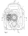
- the in the Fig. 1 to 3 Balancing machine shown has a serving as a machine base, the stability because of a heavy material, such as concrete or the like.
- Cast housing 1 which contains in an accessible from above chamber 3 a driven by an electric motor 5 spindle unit 7.
- the spindle unit 7 has a rotating spindle 11 which is arranged here with a vertical axis of rotation and has at its upper end an operationally replaceable coupling adapter 13 with a receiving opening 15 concentric with the axis of rotation 9 for connecting a standardized, indicated at 17 tool holder.
- the tool holder may be a conventional steep taper tool holder or else a hollow shaft taper holder (HSK holder).
- the spindle 11 is formed as a hollow spindle and includes an actuating device 19 explained in more detail below, which holds the tool holder 17 during the unbalance measurement in the coupling adapter 13 with the aid of a collet 21.
- the coupling adapter 13 is fastened with screws 23 to the spindle 11 and interchangeable according to the type of tool holder.
- the spindle 11 is free of play with two axially spaced ball bearings 25, 27 in a tubular cylindrical spindle holder 29 stored, wherein axial bearing clearance by biasing springs 31 and a spindle 11 enclosing the spring nut 33 is compensated.
- the electric motor 5 is arranged parallel to the axis of rotation 9 next to the spindle unit 7 and flanged together with the spindle holder 29 on the same side of a substantially plate-shaped connecting yoke 35.
- the connecting yoke 35 has a passage opening 37 for a on a shaft 39 of the electric motor 5 rotatably seated pulley 41 and a further passage opening 43 for the spindle 11, which carries at its end facing away from the coupling adapter 13 another pulley 45.
- An endless belt drive 47 establishes the drive connection between the pulleys 41, 45 and thus between the electric motor 5 and the spindle 11. Since the drive belt 47 extends near the connection yoke 35, the drive connection is comparatively stiff.
- the drive belt can also slip to some extent. So no expensive slip-free timing belt must be used.
- the consisting of the electric motor 5 and the spindle unit 7 assembly is held by means of a releasably secured to the spindle holder 29 holder receptacle 49 on the housing 1.
- the holder receptacle 49 comprises two substantially plate-shaped holder elements 51, 53 which are connected via a plurality of leaf spring elements 55 (FIG. FIG. 2 ) are spaced apart and secured together.
- the leaf spring elements 55 extend in planes parallel to one another and to the rotation axis 9, so that the leaf spring elements 55 are rigid in the spacing direction of the holder elements 51, 53 as well as in the vertical direction, while the holder elements 51, 53 are slightly deflectable in the horizontal direction by unbalanced centrifugal forces.
- Adjacent to the upper end of the spindle 11 on the one hand and adjacent to the lower end of the spindle 11 on the other hand are between pairs of the Holder elements 51, 53 on each of the other holder member to projecting projections 57, 59 of the holder elements 51, 53 each one of two force sensors 61 clamped by the spindle unit 7 in the horizontal direction of measurement on the holder elements 51, 53 at the top and on Measure the imbalance forces exerted on the lower end of the spindle unit 7. To avoid transverse forces, the force sensors 61 abut on the associated projections 57, 59 via bearing balls 63. On one of the holder elements, in the Fig.
- a further projection 65 is provided, between which the projection 59 of the other holder member 53 engages. Between the projections 65 and 59, an elastic biasing element 67 is clamped, which ensures a certain bias of the force sensor 61.
- an elastic biasing element 67 is clamped, which ensures a certain bias of the force sensor 61.
- adjusting screws 69, 71 in the projections 57 and 65 allow a position adjustment of the force sensor 61 and an adjustment of the biasing force of the biasing member 67.
- Each of the two force sensors 61 and its associated resilient biasing element are in series with each other on one of the two Support member biased supports, while the other holder element is supported in the force path between the force sensor 61 and the biasing member 67 to the force sensor 61.
- the reaction force of the biasing member 67 closes immediately over a single one of the holder elements and the leaf spring elements 55 are not loaded.
- the leaf spring elements 55 are assigned in pairs to the force sensors 61 and are also opposite pairs in the measuring direction.
- the biasing elements 67 are pivotally mounted to prevent transverse forces between tips, as for example Fig. 2 shows.
- the force sensors 61 arranged at a distance from one another at the upper and at the lower end of the spindle unit 7 are supported in a mirrored manner with respect to a axial longitudinal plane of the spindle 11 perpendicular to the direction of force on the two holder elements 51, 53.
- Fig. 2 for the upper one Force sensor 61 shows, this is based on the axis of rotation 9 in the clockwise direction seen on the projection 59 of the spindle-side holder member 53 and counterclockwise as seen from the projection 57 of the housing-side holder member 51 from.
- the lower force sensor 61 seen in the clockwise direction on the housing-side holder member 51 and counterclockwise seen supported on the spindle-side holder member 53.
- the reaction force path of the lower force sensor 61 associated biasing member 67 closes on the spindle-side holder member 53. It is understood that the Abstützweise the lower and upper force sensor 61 may be reversed. Advantage of this arrangement is that when a tilting movement of the spindle 11 both force sensors 61 are either in the same direction either pressure loaded or pressure relieved. Force direction-dependent characteristic differences of the force sensors accordingly do not influence the measurement result. It is understood that the biasing elements 67 of the two force sensors 61 are likewise arranged on opposite sides of the axial longitudinal section plane.
- the holder receptacle 49 is combined with the force sensors 61 arranged between the holder elements 51, 53 to form a second preassembled module which is attached to the housing 1 as a preassembled module is.
- the holder element 51 is screwed to the housing 1 by means of screws 73, which are accessible through holes 75 in the holder element 53 ( FIG. 3 ).
- the assembly consisting of the spindle unit 7 and the electric motor 5 is in turn indexed by means of a dovetail guide, generally designated 77, that is releasably secured in a predetermined position relative to the holder suspension 49 on its holder member 53 remote from the housing.
- the dovetail guide 77 has on the holder member 53 an axially parallel to the axis of rotation 9 extending dovetail groove 79 in which a dovetail wedge 81 is guided longitudinally displaceable.
- the dovetail wedge 81 can be fixed by means of a plurality of clamping screws 83 distributed in the longitudinal direction of the dovetail guide 77 and adjustable transversely to the longitudinal direction.
- both the dovetail groove 79 and the dovetail wedge 81 have a plurality of bayonet recesses 85 and 87, respectively, which longitudinally segment the dovetail groove 79 and the dovetail wedge 81.
- FIG. 4 shows in its right half the dovetail guide 77 in its indexed end position in which a provided on the holder member 53 stop pin 89 defines the end position of the spindle unit 7 relative to the holder suspension 49 in the direction of the dovetail guide 77.
- the segments of the dovetail wedge 81 in this case overlap the segments of the dovetail groove 79.
- the bayonet recesses 85, 87 allow the attachment of the spindle unit 7 transversely to the direction of displacement of the dovetail guide 77 near its end position, since, as FIG. 4 shows in their left half, the bayonet recesses 85, 87 openings for the segments of the bayonet groove 79 and the bayonet wedge 81 form.
- the segmentation of the dovetail guide 77 facilitates the assembly considerably.
- the resulting measurement error can be reduced if the moment arm of the Kragmoments is reduced as much as possible, the electric motor 5 is thus as close as possible to the running through the force measuring direction of the force sensors 61 vertical plane approximated.
- this is the axes of rotation 9 of the spindle 11 and the unspecified axis of rotation of the electric motor 5 containing Plane arranged so that it extends transversely to a direction perpendicular to the force measuring Axiallnaturesitessbene the spindle 11.
- the intermediate angle of these levels may also be selected smaller than 90 °.
- a further reduction of the moment arm is achieved by the dovetail wedge 81 is within the cylindrical contour of the spindle holder 29, that is incorporated in the cylindrical outer surface of the spindle holder 59. This measure also simplifies the production.
- the non-illustrated electronic control of the unbalance measuring device is housed including the associated controls in a desk-like chamber 91 of the housing 1.
- a predetermined reference position ie a zero rotational position of the spindle 11 relative to the spindle holder 29 and thus relative to the housing 1 and an information for the size of the rotational angle deviation of the current rotational position of the Spindle 11 are transmitted from this reference position.
- an information carrier ring 93 is attached to the upper, the coupling adapter 13 carrying end of the spindle, which carries a magnetic tape portion 95 on its circular cylindrical outer surface annular.
- Magnetic angle information is written on the magnetic tape section 95 at constant angular intervals, which are read by a read head assembly 97 releasably secured to the spindle holder 29 and fed to the controller.
- the magnetic tape section 95 carries both information representing the rotation angle and the information for the zero-point rotation position. Although both types of information may be recorded in a common track of the magnetic tape section 95, two adjacent tracks of information 99 are preferred. FIG. 5 ), one of which is the rotation angle information and the other is the zero point rotation information contains.
- the read head assembly 97 accordingly has two read heads associated with the individual tracks 99.
- the magnetic tape section 95 is closed in the circumferential direction, wherein, as FIG. 5 shows its abutting ends are cut obliquely in the band plane and form an oblique cut joint 101 at an acute angle to the circumferential direction of the ring 93.
- the magnetic information is written on the information carrier ring 93 after adhering the magnetic tape section 95. This has the advantage that, in spite of the oblique cut impact 101, magnetic information can also be recorded in this area.
- the bevel cut 101 at best shortens the axial height of the track available for recording.
- optical angular degrees for example in the form of radial lines 103 attached, which allow the user to manually align the spindle relative to the reference position.
- the tool holder 17 inserted into the coupling adapter 13 is fixed by the pliers 21 during operation.
- the spindle 11 is at its lower end by a lid 105 (FIG. FIG. 1 ) and forms a compressed air cylinder, in which a compressed air piston 107 is sealed for the actuation of the pliers 21 slidably.
- the compressed air supply takes place via a centric, constantly rotating compressed air rotary coupling 109 on the cover 105.
- the coupling 109 is held on a support arm 111, which in turn is arranged within the area enclosed by the drive belt 47 and on the connecting yoke 35 and thus on the spindle holder 29 is attached.
- Fig. 6 shows a variant of both a rotational angle information and a zero-rotational position information supplying measuring arrangement.
- an information carrier ring 93a is arranged, from whose circumference an annular disc 113 provided with optical angle information projects radially.
- the angle information is in turn recorded in two, not shown, radially juxtaposed tracks and are read by the optical read head assembly 97a in the transmitted light process.
- the optical information can also be read in the reflected light method, ie, reflecting.
- the annular disk 113 may also carry magnetic information, such as the circumferential information in the case of Fig. 5 also be visually readable.
- Fig. 6 carries the information carrier ring on its surface accessible from above optical angular degrees 103a for manual alignment of the spindle to the reference position.
- Fig. 7 shows a variant of the two pre-assembled assemblies comprehensive unbalance measuring device.
- the electric motor 5b and the spindle unit 7b form a preassembled module and are flanged coaxially radially next to each other at their lower ends to the connecting yoke 35b.
- For the drive connection pulleys 41b, 45b are provided, over which the belt 47b runs.
- This assembly is releasably secured to the second preassembled assembly consisting of the holder suspension 49b and the sensor assembly 61b by means of the dovetail connection 77b.
- the dovetail connection 77b in turn has a dovetail groove 79b and a dovetail wedge 81b, and may be as described in connection with FIGS FIGS. 1 to 5 explained embodiment are segmented bayonet-like and fixed by clamping screws 83b.
- the force sensors 61b held between holder elements 51b, 53b detect unbalance forces in the direction of the spacing of the holder elements 51b, 53b and are connected in one piece with a U-shaped leg spring 115.
- the leg spring 115 receives the crimping moment of the assembly of motor 5b and spindle unit 7b mounted on the holder member 53b. Again, to reduce the moment arm of the electric motor 5b to the leg spring 115 is installed approximately. It is understood that in this embodiment, too, two force sensors can be offset relative to one another in the direction of the axis of rotation 9b in order to be able to detect tilt oscillations.
- the suspension of the force sensors 61b between the holder elements 51b, 53b, the variant of the FIGS. 1 to 5 correspond.
Landscapes
- Physics & Mathematics (AREA)
- General Physics & Mathematics (AREA)
- Testing Of Balance (AREA)
Applications Claiming Priority (2)
| Application Number | Priority Date | Filing Date | Title |
|---|---|---|---|
| DE10233917A DE10233917A1 (de) | 2002-07-25 | 2002-07-25 | Unwucht-Messvorrichtung |
| EP03771099.3A EP1525445B1 (fr) | 2002-07-25 | 2003-07-24 | Dispositif de mesure de balourd |
Related Parent Applications (1)
| Application Number | Title | Priority Date | Filing Date |
|---|---|---|---|
| EP03771099.3 Division | 2003-07-24 |
Publications (2)
| Publication Number | Publication Date |
|---|---|
| EP2530447A2 true EP2530447A2 (fr) | 2012-12-05 |
| EP2530447A3 EP2530447A3 (fr) | 2012-12-19 |
Family
ID=30128391
Family Applications (3)
| Application Number | Title | Priority Date | Filing Date |
|---|---|---|---|
| EP03771099.3A Expired - Lifetime EP1525445B1 (fr) | 2002-07-25 | 2003-07-24 | Dispositif de mesure de balourd |
| EP12181726A Withdrawn EP2530447A3 (fr) | 2002-07-25 | 2003-07-24 | Dispositif de mesure de balourd |
| EP12181721.7A Expired - Lifetime EP2527811B1 (fr) | 2002-07-25 | 2003-07-24 | Dispositif de mesure de balourd |
Family Applications Before (1)
| Application Number | Title | Priority Date | Filing Date |
|---|---|---|---|
| EP03771099.3A Expired - Lifetime EP1525445B1 (fr) | 2002-07-25 | 2003-07-24 | Dispositif de mesure de balourd |
Family Applications After (1)
| Application Number | Title | Priority Date | Filing Date |
|---|---|---|---|
| EP12181721.7A Expired - Lifetime EP2527811B1 (fr) | 2002-07-25 | 2003-07-24 | Dispositif de mesure de balourd |
Country Status (11)
| Country | Link |
|---|---|
| US (1) | US7318346B2 (fr) |
| EP (3) | EP1525445B1 (fr) |
| JP (1) | JP4377327B2 (fr) |
| KR (1) | KR100956989B1 (fr) |
| CN (1) | CN100547370C (fr) |
| AU (1) | AU2003251480A1 (fr) |
| CA (1) | CA2493459A1 (fr) |
| DE (1) | DE10233917A1 (fr) |
| EA (1) | EA006408B1 (fr) |
| ES (1) | ES2410554T3 (fr) |
| WO (1) | WO2004011896A1 (fr) |
Families Citing this family (15)
| Publication number | Priority date | Publication date | Assignee | Title |
|---|---|---|---|---|
| DE102005014984A1 (de) * | 2005-04-01 | 2006-10-05 | Franz Haimer Maschinenbau Kg | Induktionsspulen-Baueinheit |
| US20090139327A1 (en) * | 2005-09-06 | 2009-06-04 | Volvo Lastvagnar Ab | Method and a system for determining wheel imbalances of at least one wheel on a vehicle |
| DE102006005790B4 (de) * | 2005-12-16 | 2014-10-23 | Horst Warkotsch | Haltevorrichtung für eine Felge eines Fahrzeugrades |
| JP4807185B2 (ja) * | 2006-08-29 | 2011-11-02 | 株式会社Ihi | 回転体のバランス修正方法及び装置 |
| JP5288320B2 (ja) * | 2007-04-18 | 2013-09-11 | 株式会社Ihi | 高速回転体の回転バランス計測装置及び方法 |
| JP5403952B2 (ja) * | 2008-06-11 | 2014-01-29 | 株式会社神戸製鋼所 | タイヤ試験機及びタイヤ試験方法 |
| DE102008062255A1 (de) * | 2008-12-15 | 2010-06-17 | Franz Haimer Maschinenbau Kg | Wuchtvorrichtung mit Zusatzlager |
| BR112012007536A2 (pt) * | 2009-10-02 | 2016-12-06 | Franz Haimer Maschb Kg | dispositivo de aperto de fuso |
| US8429968B2 (en) * | 2009-10-08 | 2013-04-30 | Moscow Mills, Inc. | Balance test indexing tool for balance-testing a rotor |
| DE202009016532U1 (de) | 2009-10-30 | 2010-03-18 | Franz Haimer Maschinenbau Kg | Wuchtmaschine mit automatisierter Umschlagmessung |
| CN104897342B (zh) * | 2015-07-01 | 2017-06-16 | 无锡威孚高科技集团股份有限公司 | 车用增压器涡轮轴部件动平衡测量用的空气轴承装置 |
| US10267335B1 (en) | 2015-09-23 | 2019-04-23 | Anthony Freakes | Methods and apparatus for mounting an impeller with positional repeatability |
| DE102017007328B4 (de) * | 2017-08-04 | 2019-05-09 | Schenck Rotec Gmbh | Antriebseinrichtung für eine Auswuchtmaschine sowie Auswuchtmaschine |
| CN108672733B (zh) * | 2018-04-19 | 2023-11-17 | 中信戴卡股份有限公司 | 一种车轮夹具 |
| DE102020002699A1 (de) | 2019-05-20 | 2020-11-26 | Sew-Eurodrive Gmbh & Co Kg | Antrieb, aufweisend einen Elektromotor und ein von dem Elektromotor angetriebenes Taumelgetriebe |
Citations (2)
| Publication number | Priority date | Publication date | Assignee | Title |
|---|---|---|---|---|
| WO2000045983A1 (fr) | 1999-02-01 | 2000-08-10 | Franz Haimer Maschinenbau Kg | Dispositif de serrage pour la fixation d'un element de machine rotatif, et machine a equilibrer pourvue d'un tel dispositif de serrage |
| WO2001089758A1 (fr) | 2000-05-22 | 2001-11-29 | Franz Haimer Gmbh | Dispositif de contraction pour un porte-outil |
Family Cites Families (15)
| Publication number | Priority date | Publication date | Assignee | Title |
|---|---|---|---|---|
| CH610404A5 (fr) * | 1975-10-27 | 1979-04-12 | Luigi Buzzi | |
| DE2700098A1 (de) * | 1976-05-07 | 1977-11-10 | Carlo Buzzi | Auswuchtmaschine, deren antriebsmotor als traeger fuer den auszuwuchtenden drehkoerper dient |
| JPS5647709A (en) * | 1979-09-28 | 1981-04-30 | Hitachi Ltd | Encoder |
| DE3026232C2 (de) * | 1980-07-10 | 1984-07-12 | Gebr. Hofmann Gmbh & Co Kg Maschinenfabrik, 6100 Darmstadt | Verfahren und Vorrichtung zur Größenanzeige einer Unwucht beim Auswuchten von Rotoren |
| IT1146578B (it) * | 1981-02-19 | 1986-11-12 | Buzzi Dr Ing Carlo | Supporzo per macchina equilibratrice |
| DE3109586A1 (de) * | 1981-03-13 | 1982-09-30 | Werner 5905 Freudenberg Mäusezahl | "an einem beweglichen maschinenteil anzubringender impulsgeberbauteil" |
| DE3242109A1 (de) * | 1982-11-13 | 1984-05-17 | Robert Bosch Gmbh, 7000 Stuttgart | Vorrichtung zur erfassung der drehzahl eines rotierenden teils |
| ATE96538T1 (de) * | 1989-01-17 | 1993-11-15 | Alsthom Gec | Vorrichtung zur ermittlung der lage einer mit einem elektrisch diskontinuierlich leitenden band umgebenen rotierenden stahlwelle sowie verfahren zur herstellung des bandes. |
| JPH07104220B2 (ja) * | 1989-12-18 | 1995-11-13 | 株式会社大沢製作所 | バランシングマシン |
| US6336364B1 (en) * | 1996-01-31 | 2002-01-08 | Hunter Engineering Company | Wheel balancer with wheel rim runout measurement |
| US6854329B2 (en) * | 1996-01-31 | 2005-02-15 | Hunter Engineering Company | Wheel balancer with variation measurement |
| US6324908B1 (en) * | 1996-01-31 | 2001-12-04 | Hunter Engineering Company | Wheel balancer and control circuit therefor |
| EP0924502A3 (fr) * | 1997-12-16 | 1999-07-07 | Kokusai Keisokuki Kabushiki Kaisha | Dispositif de mesure de l' uniformité et /ou de l' equilibre dynamique de pneumatique |
| US6430992B1 (en) * | 1998-09-02 | 2002-08-13 | Snap-On Technologies, Inc. | Device for measuring the forces generated by a rotor Imbalance |
| US6658936B2 (en) * | 2001-03-08 | 2003-12-09 | Kokusai Keisokuki Kabushiki Kaisha | Apparatus and method for measuring uniformity and/or dynamic balance of tire |
-
2002
- 2002-07-25 DE DE10233917A patent/DE10233917A1/de not_active Withdrawn
-
2003
- 2003-07-24 CN CNB038203170A patent/CN100547370C/zh not_active Expired - Fee Related
- 2003-07-24 EP EP03771099.3A patent/EP1525445B1/fr not_active Expired - Lifetime
- 2003-07-24 AU AU2003251480A patent/AU2003251480A1/en not_active Abandoned
- 2003-07-24 CA CA002493459A patent/CA2493459A1/fr not_active Abandoned
- 2003-07-24 WO PCT/EP2003/008183 patent/WO2004011896A1/fr not_active Ceased
- 2003-07-24 EP EP12181726A patent/EP2530447A3/fr not_active Withdrawn
- 2003-07-24 EP EP12181721.7A patent/EP2527811B1/fr not_active Expired - Lifetime
- 2003-07-24 EA EA200500260A patent/EA006408B1/ru not_active IP Right Cessation
- 2003-07-24 JP JP2004523797A patent/JP4377327B2/ja not_active Expired - Fee Related
- 2003-07-24 US US10/522,088 patent/US7318346B2/en not_active Expired - Fee Related
- 2003-07-24 ES ES03771099T patent/ES2410554T3/es not_active Expired - Lifetime
- 2003-07-24 KR KR1020057001358A patent/KR100956989B1/ko not_active Expired - Fee Related
Patent Citations (2)
| Publication number | Priority date | Publication date | Assignee | Title |
|---|---|---|---|---|
| WO2000045983A1 (fr) | 1999-02-01 | 2000-08-10 | Franz Haimer Maschinenbau Kg | Dispositif de serrage pour la fixation d'un element de machine rotatif, et machine a equilibrer pourvue d'un tel dispositif de serrage |
| WO2001089758A1 (fr) | 2000-05-22 | 2001-11-29 | Franz Haimer Gmbh | Dispositif de contraction pour un porte-outil |
Also Published As
| Publication number | Publication date |
|---|---|
| JP2005534019A (ja) | 2005-11-10 |
| US7318346B2 (en) | 2008-01-15 |
| EA006408B1 (ru) | 2005-12-29 |
| ES2410554T3 (es) | 2013-07-02 |
| EA200500260A1 (ru) | 2005-08-25 |
| KR100956989B1 (ko) | 2010-05-11 |
| WO2004011896A1 (fr) | 2004-02-05 |
| EP2527811B1 (fr) | 2017-12-06 |
| EP1525445B1 (fr) | 2013-05-22 |
| KR20050051635A (ko) | 2005-06-01 |
| AU2003251480A2 (en) | 2004-02-16 |
| EP2527811A2 (fr) | 2012-11-28 |
| DE10233917A1 (de) | 2004-02-12 |
| EP1525445A1 (fr) | 2005-04-27 |
| JP4377327B2 (ja) | 2009-12-02 |
| EP2530447A3 (fr) | 2012-12-19 |
| CA2493459A1 (fr) | 2004-02-05 |
| US20050235750A1 (en) | 2005-10-27 |
| CN100547370C (zh) | 2009-10-07 |
| AU2003251480A1 (en) | 2004-02-16 |
| CN1678895A (zh) | 2005-10-05 |
| EP2527811A3 (fr) | 2014-01-01 |
Similar Documents
| Publication | Publication Date | Title |
|---|---|---|
| EP1525445B1 (fr) | Dispositif de mesure de balourd | |
| DE10008710C2 (de) | Vorrichtung zum zentrierenden Spannen von optischen Linsen für deren Randbearbeitung | |
| EP2493647B1 (fr) | Outil de tournage précis | |
| EP1575739B1 (fr) | Dispositif et procede de serrage centre de pieces destinees a etre entrainees par rotation | |
| DE3527546C1 (de) | Vorrichtung zum Verbinden einer Positionsmesseinrichtung mit zwei relativ zueinander beweglichen Objekten | |
| EP0373514A1 (fr) | Dispositif pour mesurer simultanément les diamètres intérieurs d'alésages consécutifs | |
| DE102005007038A1 (de) | Werkstückspindelstock | |
| DE202011101445U1 (de) | Beidseits verschwenkbares Vorritzsägeaggregat | |
| DE102011116695B4 (de) | Vorrichtung zum Einpressen und Auswuchten von Gelenkwellen oder Gelenkwellensträngen | |
| DE102016201466B3 (de) | Dreheinheit für ein Koordinatenmessgerät | |
| DE10139297C1 (de) | Einrichtung zur lagegenauen Aufnahme eines Zusatzelementes auf einem Träger | |
| DE102013111599A1 (de) | Spindel einer Werkzeugschleifmaschine | |
| EP0922528B1 (fr) | Porte outil pour outil rotatif, permettant un réglage radial continu de l'outil | |
| DE2701876C3 (de) | Vorrichtung zum Messen der Unwuchten von Rotoren, insbesondere von Fahrzeugrädern | |
| DE4028076A1 (de) | Messeinrichtung fuer rotationssymmetrische werkstuecke | |
| EP0322579B1 (fr) | Dispositif de centrage de lentilles optiques pour le montage mécanique, en particulier lors du meulage des bords et de facettes | |
| DE202005018193U1 (de) | Spannvorrichtung | |
| CH671177A5 (fr) | ||
| WO1998021548A1 (fr) | Dispositif de mesure | |
| EP1862047A2 (fr) | Unite d'entrainement pour element fonctionnel mobile | |
| DE3617790A1 (de) | Ultraschallbearbeitungsmaschine | |
| DE3823323C1 (en) | Device for rotating an optical waveguide and application of this device | |
| DE3532942A1 (de) | Vorrichtung zum mitnehmen eines zwischen spitzen eingespannten werkstuecks | |
| EP0670989A1 (fr) | Procede et dispositif permettant de mesurer des coordonnees | |
| DE3520683A1 (de) | Verfahren und vorrichtung zur schlagmessung an zusammengebauten kugellagern |
Legal Events
| Date | Code | Title | Description |
|---|---|---|---|
| PUAL | Search report despatched |
Free format text: ORIGINAL CODE: 0009013 |
|
| PUAI | Public reference made under article 153(3) epc to a published international application that has entered the european phase |
Free format text: ORIGINAL CODE: 0009012 |
|
| 17P | Request for examination filed |
Effective date: 20120824 |
|
| AC | Divisional application: reference to earlier application |
Ref document number: 1525445 Country of ref document: EP Kind code of ref document: P |
|
| AK | Designated contracting states |
Kind code of ref document: A2 Designated state(s): AT BE BG CH CY CZ DE DK EE ES FI FR GB GR HU IE IT LI LU MC NL PT RO SE SI SK TR |
|
| AK | Designated contracting states |
Kind code of ref document: A3 Designated state(s): AT BE BG CH CY CZ DE DK EE ES FI FR GB GR HU IE IT LI LU MC NL PT RO SE SI SK TR |
|
| RIC1 | Information provided on ipc code assigned before grant |
Ipc: G01M 1/06 20060101ALI20121112BHEP Ipc: G01M 1/04 20060101AFI20121112BHEP |
|
| 17Q | First examination report despatched |
Effective date: 20170503 |
|
| STAA | Information on the status of an ep patent application or granted ep patent |
Free format text: STATUS: THE APPLICATION IS DEEMED TO BE WITHDRAWN |
|
| 18D | Application deemed to be withdrawn |
Effective date: 20170914 |