EP2530495A1 - Reflektive filmbeschichtung - Google Patents
Reflektive filmbeschichtung Download PDFInfo
- Publication number
- EP2530495A1 EP2530495A1 EP11734813A EP11734813A EP2530495A1 EP 2530495 A1 EP2530495 A1 EP 2530495A1 EP 11734813 A EP11734813 A EP 11734813A EP 11734813 A EP11734813 A EP 11734813A EP 2530495 A1 EP2530495 A1 EP 2530495A1
- Authority
- EP
- European Patent Office
- Prior art keywords
- layer
- film
- reflective film
- film laminate
- laminate
- Prior art date
- Legal status (The legal status is an assumption and is not a legal conclusion. Google has not performed a legal analysis and makes no representation as to the accuracy of the status listed.)
- Withdrawn
Links
Images

Classifications
-
- C—CHEMISTRY; METALLURGY
- C23—COATING METALLIC MATERIAL; COATING MATERIAL WITH METALLIC MATERIAL; CHEMICAL SURFACE TREATMENT; DIFFUSION TREATMENT OF METALLIC MATERIAL; COATING BY VACUUM EVAPORATION, BY SPUTTERING, BY ION IMPLANTATION OR BY CHEMICAL VAPOUR DEPOSITION, IN GENERAL; INHIBITING CORROSION OF METALLIC MATERIAL OR INCRUSTATION IN GENERAL
- C23C—COATING METALLIC MATERIAL; COATING MATERIAL WITH METALLIC MATERIAL; SURFACE TREATMENT OF METALLIC MATERIAL BY DIFFUSION INTO THE SURFACE, BY CHEMICAL CONVERSION OR SUBSTITUTION; COATING BY VACUUM EVAPORATION, BY SPUTTERING, BY ION IMPLANTATION OR BY CHEMICAL VAPOUR DEPOSITION, IN GENERAL
- C23C14/00—Coating by vacuum evaporation, by sputtering or by ion implantation of the coating forming material
- C23C14/06—Coating by vacuum evaporation, by sputtering or by ion implantation of the coating forming material characterised by the coating material
- C23C14/14—Metallic material, boron or silicon
- C23C14/20—Metallic material, boron or silicon on organic substrates
- C23C14/205—Metallic material, boron or silicon on organic substrates by cathodic sputtering
-
- C—CHEMISTRY; METALLURGY
- C22—METALLURGY; FERROUS OR NON-FERROUS ALLOYS; TREATMENT OF ALLOYS OR NON-FERROUS METALS
- C22C—ALLOYS
- C22C5/00—Alloys based on noble metals
- C22C5/06—Alloys based on silver
-
- F—MECHANICAL ENGINEERING; LIGHTING; HEATING; WEAPONS; BLASTING
- F21—LIGHTING
- F21V—FUNCTIONAL FEATURES OR DETAILS OF LIGHTING DEVICES OR SYSTEMS THEREOF; STRUCTURAL COMBINATIONS OF LIGHTING DEVICES WITH OTHER ARTICLES, NOT OTHERWISE PROVIDED FOR
- F21V7/00—Reflectors for light sources
- F21V7/22—Reflectors for light sources characterised by materials, surface treatments or coatings, e.g. dichroic reflectors
- F21V7/24—Reflectors for light sources characterised by materials, surface treatments or coatings, e.g. dichroic reflectors characterised by the material
-
- G—PHYSICS
- G02—OPTICS
- G02B—OPTICAL ELEMENTS, SYSTEMS OR APPARATUS
- G02B5/00—Optical elements other than lenses
- G02B5/08—Mirrors
- G02B5/0808—Mirrors having a single reflecting layer
-
- F—MECHANICAL ENGINEERING; LIGHTING; HEATING; WEAPONS; BLASTING
- F21—LIGHTING
- F21S—NON-PORTABLE LIGHTING DEVICES; SYSTEMS THEREOF; VEHICLE LIGHTING DEVICES SPECIALLY ADAPTED FOR VEHICLE EXTERIORS
- F21S41/00—Illuminating devices specially adapted for vehicle exteriors, e.g. headlamps
- F21S41/30—Illuminating devices specially adapted for vehicle exteriors, e.g. headlamps characterised by reflectors
- F21S41/37—Illuminating devices specially adapted for vehicle exteriors, e.g. headlamps characterised by reflectors characterised by their material, surface treatment or coatings
Definitions
- the present invention relates to a reflective film laminate, and a lighting tool for a vehicle, an illuminator, or an optical mirror that has this reflective film laminate.
- a pure Ag film or an Ag-based alloy film which may be referred to as an Ag film hereinafter, comes to give a high reflectivity (reflection ratio) against visible rays when the film has a film thickness of 70 nm or more.
- the Ag film is widely used as a reflective film for a vehicle in which a light source that may be of various types, such as a halogen lamp, an HID or an LED, is used.
- a light source that may be of various types, such as a halogen lamp, an HID or an LED
- Ag atoms in the Ag film have a property of aggregating easily; thus, the front surface of the Ag film is made rough by the aggregation, so that the film may be lowered in reflectivity.
- Examples of the cause of the aggregation of the Ag atoms include the adsorption of sulfur or some other in the atmosphere onto the Ag film front surface, and the exposure of the reflective film to a high-temperature environment of about 80 to 200°C temperature by heat radiated from various light sources.
- Patent Literature 1 discloses a lighting tool for a vehicle in which a protective film made of a modified silicone resin is formed on an Ag film.
- Patent Literature 2 discloses a reflective film having, on an Ag film, a protective film made of a metal oxide such as ITO.
- Patent Literature 3 discloses a reflective film in which a protective film that is a titanium film or titanium alloy film is formed on an Ag film.
- Patent Literatures 4 and 5 each disclose a reflective film in which a layer of a metal oxide of Si, Al or Ti is formed on an Ag film containing Bi or some other element.
- the protective film is made of a modified silicone resin as disclosed in Patent Literature 1
- sulfur or some other component may diffuse or penetrate into the resin, or the resin material may be deteriorated in a high-temperature environment.
- the protective film is made of a metal oxide such as ITO, or is rendered a titanium film or titanium alloy film as disclosed in Patent Literature 2 or 3
- sulfur or some other component may invade the reflective film through pinholes in the protective film.
- the Ag atoms aggregate so that many white dots or discolorations are generated in the Ag film front surface, so that the reflective film may be declined in reflectivity or the product concerned may be deteriorated in design or merchandise performance, or some other performance.
- a metal oxide film is formed as the protective film. However, at the time of the formation, a sputtering target made of the metal oxide is used. Thus, pinholes may be made in the metal oxide layer.
- the protective film does not easily make the high reflectivity of the Ag film low; the protective film itself has an excellent sulfurization resistance and heat resistance; sulfur and some other component do not diffuse or penetrate into the protective film; and the protective film has no pinholes.
- An object of the invention is to provide a reflective film laminate formed to have an Ag film, and having a protective film which is high in initial reflectivity and excellent in sulfurization resistance and heat resistance, and which is made as small as possible in the number of pinholes, so that the reflective film laminate does not easily undergo a decline in reflectivity that is caused by the aggregation of Ag atoms in the Ag film.
- the reflective film laminate of the invention that has solved the above-mentioned problems is a reflective film laminate comprising a substrate, a pure Ag film or an Ag-based alloy film as a first layer over the substrate, and an oxide film as a second layer laid over the first layer, the oxide film being an oxide film of one or more metals selected from the group consisting of Zr, Cr, Nb, Hf, Ta, V, Ni, Mo, W, Al and Si, in which the second layer has a thickness of 0.1 to 10 nm, and further by the laying of the second layer, the reflectivity of the reflective film laminate is deteriorated by 30% or less.
- the wording "over the substrate” or “over the (first) layer” includes, as the meaning thereof, a case where the first layer is laid directly on the substrate, or the second layer is laid directly on the first layer; and a case where the first layer or the second layer is laid over the substrate or the first layer to interpose any other layer therebetween.
- the first layer has an average crystal grain diameter of 100 nm or less.
- the first layer is an Ag-based alloy film comprising Bi in a proportion of 0.02 atomic percent or more; the first layer is the Ag-based alloy film that further comprises Ge in a proportion of 0.02 atomic percent or more; the first layer is the Ag-based alloy film that further comprises one or more selected from the group consisting of Au, Pt, Pd, and Rh in a proportion of 0.1 to 5 atomic percent; or the first layer is the Ag-based alloy film that further comprises one or more selected from the group consisting of Cu, Sn, Al, Cr, V, Mo, Ru, Ir and Si in a proportion of 0.1 atomic percent or more.
- the first layer is an Ag-based alloy that comprises one or more selected from the group consisting of Cu, Sn and Al in a proportion of 0.1 atomic percent or more.
- An additional preferred embodiment of the reflective film laminate of the invention has, as the second layer, an oxide film of one or more metals selected from the group consisting of Zr, Cr, Nb, and Ta; or the laminate has a plasma polymerized film or a resin film as a third layer over the second layer.
- the invention includes, as one aspect thereof, a method for producing the above-mentioned reflective film laminate comprising the step of forming the above-mentioned first layer over a substrate, and the step of using a sputtering target comprising the above-mentioned metal(s) to perform sputtering over the first layer, thereby forming a sputtered thin film, and next oxidizing the sputtered thin film in an atmosphere containing oxygen, thereby forming the above-mentioned second layer.
- oxidizing includes, as the meaning thereof, a case where the sputtered thin film is intentionally oxidized in an atmosphere containing oxygen, and a case where a laminate comprising the sputtered thin film formed over the first layer is merely allowed to stand still in an atmosphere containing oxygen, so that the sputtered thin film is oxidized.
- the second layer comprising the oxide film of the predetermined metal(s), the sputtering target of the above-mentioned metal(s), which is not a sputtering target of any metal oxide, is used to perform sputtering to form a thin film, and next this thin film is oxidized. It is therefore possible to gain an effect of closing or stopping pinholes by volume-expansion generated when the metal(s) is/are oxidized.
- the invention further includes, as aspects thereof, a light tool for a vehicle, an illuminator, and an optical mirror that each comprise the above-mentioned reflective film laminate.
- the Ag film (the first layer), which exhibits a high reflectivity, is protected by the oxide film (the second layer) of the predetermined metal(s), which exhibits endurance against sulfur and heat.
- the reflective film laminate is excellent in sulfurization resistance and heat resistance.
- the deterioration (the deterioration ratio) in the reflectivity of the reflective film laminate, which is caused by laying the second layer is restrained into 30% or less, so that the reflective film laminate is high in initial reflectivity. It is therefore expected that the reflective film laminate keeps a high reflectivity over a long term.
- the high reflectivity can be kept over a long term, the following is expected: when the reflective film laminate of the invention is used as a lighting tool for a vehicle, an illuminator or an optical mirror, the endurance thereof is improved.
- the reflective film laminate of the invention is a reflective film laminate including a substrate, a pure Ag film or an Ag-based alloy film as a first layer over the substrate, and an oxide film as a second layer laid over the first layer, the oxide film being an oxide film of one or more metals selected from the group consisting of Zr, Cr, Nb, Hf, Ta, V, Ni, Mo, W, Al and Si, in which the second layer has a thickness of 0.1 to 10 nm, and further by the laying of the second layer, the reflectivity of the reflective film laminate is deteriorated by 30% or less.
- the inventors have made eager investigations to provide a reflective film laminate which includes an Ag film, which has a high reflectivity required for a lighting tool for a vehicle, an illuminator, an optical mirror or some other, and which can further prevent the aggregation of Ag atoms in the Ag film.
- the inventors have found out that it is effective to form, over an Ag film, an oxide film of one or more predetermined metals, such as Zr, as a second layer.
- the oxide layer of the predetermined metal(s), such as Zr, which forms the second layer, does not undergo the diffusion or penetration of sulfur, and the layer itself has an excellent sulfurization resistance and heat resistance.
- a metal film of the predetermined metal(s), such as Zr is beforehand formed and subsequently the metal film is oxidized to form the metal oxide film; the predetermined metal(s), such as Zr, is/are expanded in volume by the oxidization, and the expansion can be expected to produce an advantageous effect of restraining the formation of pinholes in the metal oxide film (the second layer).
- the thickness of the second layer can be made as small as a value of 0.1 to 10 nm.
- the high reflectivity of the Ag film can be prevented from being deteriorated.
- the reflectivity the reflectivity of only the first layer, the reflectivity of the reflective film laminate after the lamination of the second layer
- the deterioration by the laying of the second layer can be restrained into 30% or less.
- the first layer that the invention has is a layer for causing the laminate to exhibit a high reflectivity, and is formed as a pure Ag film or an Ag-based alloy film.
- a pure Ag film shows a very high reflectivity of about 96% when the film thickness thereof is 70 nm or more.
- the film may undergo aggregation (of atoms therein) by heating.
- an Ag-based alloy film as the first layer. Examples thereof include Ag-based alloy films described in Patent Literatures 2 to 5 described above.
- a Ag-based alloy film containing Bi is in particular preferably used.
- the lower limit of the Bi content by percentage in the Ag-based alloy film is set preferably to 0.02 atomic percent (more preferably to 0.03 atomic percent, even more preferably to 0.05 atomic percent, in particular preferably to 0.08 atomic percent).
- the upper limit of the Bi content by percentage is set preferably to 0.3 atomic percent (more preferably to 0.25 atomic percent, even more preferably to 0.2 atomic percent).
- this Ag-based alloy film is a film which contains Bi in the above-mentioned quantity and contains, as the balance, Ag and inevitable impurities.
- the Bi-containing Ag-based alloy film which is used as the first layer in the invention, may further contain an element other than Bi as the Ag-based alloy film described in, for example, Patent Literature 4 or 5 does.
- the Ag-based alloy film that further contains Ge may be used.
- Ge has an effect of restraining the growth of crystal grains of Ag, and the aggregation, which are each caused by heat. Ge also has an effect of heightening the sulfurization resistance of the Ag-based alloy film, and restraining discoloration of the Ag-based alloy film that is caused when the Ag-based alloy film is brought in contact with sulfur in hydrogen sulfide, or some other component that is contained in the air.
- the lower limit of the Ge content by percentage in the Ag-based alloy film is set preferably to 0.02 atomic percent (more preferably to 0.05 atomic percent, even more preferably to 0.08 atomic percent).
- the upper limit of the Ge content by percentage is set preferably to 1 atomic percent (more preferably to 0.5 atomic percent). Even if Ge is incorporated into the layer in a content by percentage more than 1 atomic percent, the above-mentioned improvement effect is saturated while the reflective film laminate is lowered in reflectivity.
- this Ag-based alloy film is a film which contains Bi and Ge in the above-mentioned respective quantities and contains, as the balance, Ag and inevitable impurities.
- the Bi-containing Ag-based alloy film which is used as the first layer in the invention, may contain, instead of or together with Ge, one or more selected from the group consisting of Au, Pt, Pd and Rh, which may be referred to merely as the "M1 elements" hereinafter.
- M1 elements Au, Pt and Pd are preferred, and Au and Pt are more preferred.
- the M1 elements each have an effect of restraining the aggregation of Ag atoms that is caused by water or halogens (such as NaCl).
- the lower limit of the total content by percentage of one or more of the M1 elements (when the first layer contains one of the M1 elements, the total content is the content by percentage of only the one element; and when the layer contains two or more elements thereof, the total content is the total content by percentage of the two or more elements) is set preferably to 0.1 atomic percent (more preferably to 0.3 atomic percent).
- the upper limit of the total content by percentage of one or more of the M1 elements is set preferably to 5 atomic percent (more preferably to 3 atomic percent). If the total content by percentage of one or more of the M1 elements is less than 0.1 atomic percent, the effect of restraining the aggregation of the Ag atoms (the effect of improving the Ag film in humidity resistance and halogen resistance) is small. On the other hand, if the total content by percentage is more than 5 atomic percent, costs may increase, and the Ag film may be lowered in initial reflectivity, humidity resistance, halogen resistance and others.
- this Ag-based alloy film examples include a film which contains Bi and one or more of the M1 elements in the above-mentioned respective quantities, and contains, as the balance, Ag and inevitable impurities; and a film which contains Bi, Ge and one or more of the M1 elements in the above-mentioned respective quantities, and contains the same balance.
- the latter embodiment is most preferred since the Ag film itself can have an excellent sulfurization resistance and heat resistance.
- the Bi-containing Ag-based alloy film which is used as the first layer in the invention, may contain, instead of or together with Ge and/or one or more of the M1 elements, one or more selected from the group consisting of Cu, Sn, Al, Cr, V, Mo, Ru, Ir and Si, which may be referred to merely as the "M2 elements" hereinafter.
- M2 elements preferred are Cu, Sn and Al.
- the M2 elements each have a nature of being concentrated in any surface of the Ag-based alloy film.
- each of the M2 elements that is contained in the first layer receives heat, thereby being diffused and concentrated from the surface of the Ag-based alloy film into the second layer.
- the reflective film laminate is greatly improved in endurance, in particular, heat resistance.
- the lower limit of the total content by percentage of one or more of the M2 elements (when the first layer contains one of the M2 elements, the total content is the content by percentage of only the one element; and when the layer contains two or more elements thereof, the total content is the total content by percentage of the two or more elements) is set desirably to 0.1 atomic percent (more preferably to 0.3 atomic percent).
- the upper limit of the total content by percentage of one or more of the M2 elements is set preferably to 5 atomic percent (more preferably to 3 atomic percent).
- the total content by percentage of one or more of the M2 elements is less than 0.1 atomic percent, the quantity of the one or more of the M2 elements concentrated into the second layer is small so that the effect of sealing pinholes in the second layer is small.
- the total content by percentage is more than 5 atomic percent, costs may increase or the reflective film laminate may be lowered in initial reflectivity.
- This Ag-based alloy film is, for example, a film which contains Bi and one or more of the M2 elements in the above-mentioned respective quantities, contains Bi, Ge and one or more of the M2 elements in the above-mentioned respective quantities, or contains Bi, Ge, one or more of the M1 elements, and one or more of the M2 elements in the above-mentioned respective quantities; and which further contains, as the balance, Ag and inevitable impurities.
- a film which contains Bi, Ge, one or more of the M1 elements and one or more of the M2 elements in the above-mentioned respective quantities; and which contains, as the balance, Ag and inevitable impurities since the Ag film itself can have an excellent sulfurization resistance and heat resistance, and can make a further improvement in the protecting performance of the protective film.
- the first layer that the invention has is preferably controlled to have an average crystal grain diameter of 100 nm or less.
- the formation of pinholes in the metal oxide film (the second layer) is restrained.
- the volume-expansion based on the oxidization of the metal(s) has a limitation.
- the film of the metal(s) formed on the first layer before the oxidization is low in nucleus generation density, the formation of the pinholes may be unable to be sufficiently restrained even by the volume-expansion.
- the pinhole-sealing effect based on the volume-expansion of the metal(s) can be sufficiently expected.
- the pinhole-sealing effect makes a sufficient improvement of the reflective film laminate in sulfurization resistance and heat resistance even when the film thickness of the second layer is made small (0.1 to 10 nm).
- the laminate can be restrained from being lowered in initial reflectivity without needing to make the second layer thick.
- the diameter of the first layer is preferably 90 nm or less, more preferably 80 nm or less, even more preferably 60 nm or less. If the average crystal grain diameter of the first layer is more than 100 nm, the resultant sulfurization resistance and heat resistance of the reflective film laminate may not be sufficiently improved. The reason therefor is assumed as follows: if the crystal average grain diameter of the first layer is more than 100 nm, the metal film (before oxidized) formed on the first layer is lowered in nucleus generation density so that the volume-expansion generated at the time of oxidizing the metal film does not give a sufficient pinhole-sealing effect.
- the lower limit of the average crystal grain diameter of the first layer is not particularly limited, and is preferably 15 nm from the viewpoint of production costs.
- the second layer that the invention has is a layer for causing the reflective film laminate to exhibit endurance against heat and sulfur, and is characterized by being an oxide film of one or more metals selected from the group consisting of Zr, Cr, Nb, Hf, Ta, V, Ni, Mo, W, Al and Si.
- the metal or each of the metals that constitute the second layer is a component selected as a metal having a PB ratio (pilling-bedworth ratio: "the volume of the metal oxide per unit mole” / "that of the metal per unit mole") more than 1 so as to be expanded in volume when oxidized.
- the metal can be expected to give an effect of restraining the formation of pinholes when oxidized.
- the metal oxide thereof itself is excellent in endurance, so that it hardly occurs that the second layer is deteriorated and the Ag film (the first layer) is also deteriorated accordingly.
- the metal damages the high reflectivity of the Ag film as the first layer, which is a characteristic of this film, when the metal is in a metal film state; however, when the metal is made into the oxide, the metal becomes transparent. Thus, the metal oxide can prevent a decline in the reflectivity of the Ag film.
- the metal(s) constituting the second layer has/have a PB ratio more than 1 as described above, the metal(s) is/are expanded in volume when oxidized, so as to produce an advantageous effect of sealing pinholes.
- the PB ratio of the metal(s) is close to 1, the pinhole-sealing effect of the metal(s) is small.
- the PB ratio is preferably 1.3 or more.
- the PB ratio of the metal(s) is preferably 4.0 or less (more preferably 3.5 or less, even more preferably 3.0 or less). From this viewpoint, it is preferred in the invention to use, out of the above-mentioned metals, one or more selected from the group consisting of Zr, Cr, Nb, Ta and Ni.
- the film thickness of the second layer is set to 0.1 nm or more (preferably 0.15 nm or more, more preferably 0.2 nm or more), and 10 nm or less (preferably 7 nm or less, more preferably 5 nm or less).
- a metal oxide film (as the second layer) can be obtained in which the metal is oxidized over the whole in the film thickness direction of the film.
- the second layer can be made transparent to prevent a decline in the initial reflectivity of the reflective film laminate of the invention.
- the deterioration in the reflectivity of the laminate can be restrained to 30% or less (preferably 15% or less, more preferably 5% or less, even more preferably 0.5% or less). If the deterioration in the reflectivity is more than 30%, the reflective film laminate of the invention is lowered in initial reflectivity, so that the laminate may be unable to be used for articles for which a high reflectivity is required.
- the second layer is preferably a layer that is sufficiently oxidized over the whole in the film thickness direction of the film.
- the second layer is not limited to this layer as far as the effect that the deterioration in the reflectivity is restrained into 30% or less by the laying of the second layer is exhibited.
- the second layer may be composed of a (topmost) surface that is sufficiently oxidized, and a metal film (metal layer) that is not sufficiently oxidized.
- the second layer may be an embodiment in which from the second layer (topmost) surface, the concentration of the metal oxide gradually becomes lower in the film thickness direction.
- the second layer When the second layer is formed over the first layer having an average crystal grain diameter of 100 nm or less, the effect of sealing pinholes by the oxidization is sufficiently obtained; thus, even when the film thickness of the second layer is set into the above-mentioned range, the reflective film laminate easily comes to exhibit an excellent sulfurization resistance and heat resistance.
- the film thickness of the second layer is less than 0.1 nm, the above-mentioned improvement effect by the laying of the second layer may be unable to be sufficiently exhibited.
- the pinhole size becomes smaller.
- the second layer is not easily oxidized over the whole thereof in the film thickness direction, so that the second layer is not made transparent.
- the initial reflectivity of the reflective film laminate of the invention may be deteriorated.
- the reflective film laminate of the invention may have, over the second layer thereof, a plasma polymerized film or a resin film.
- the reflective film laminate of the invention can be made higher in endurance so that the laminate can keep the high reflectivity thereof over a longer term.
- this organic silicon include hexamethyldisiloxane, hexamethyldisilazane, and triethoxysilane.
- the film thickness of the plasma polymerized film is preferably from 5 to 500 nm, more preferably from 10 to 400 nm. If the film thickness is made small, the film becomes low in barrier performance. On the other hand, if the film thickness is made larger, the stress of the film becomes large; thus, after stacked and formed, the plasma polymerized film may be cracked or peeled when the reflective film laminate is caused to undergo a heat resistance test or a humidity resistance test.
- the resin material that forms the resin film examples include acrylic resin, and silicone resin.
- the film thickness of the resin layer is preferably from 0.1 to 20 ⁇ m. If the film thickness is outside this range, the same problems as described above may be caused.
- the material of the substrate used in the reflective film laminate of the invention is not particularly limited.
- the material is not particularly limited as far as the material is a material that is ordinarily used in the field of illuminators, lighting tools for vehicles, and others that each have an Ag film.
- the material is, for example, a resin, or glass.
- the resin include polycarbonate resin, acrylic resin, polyester resins such as PET (polyethylene terephthalate) and PBT (polybutylene terephthalate), ABS resin, epoxy resin, acetal resin, and alicyclic hydrocarbon resins. These resins may be used in a mixture form.
- the material of the substrate is decided in accordance with the temperature of heat radiated from the light source (concerned).
- the temperature of the light source is, for example, about 180°C or higher, the use of glass is preferred.
- the temperature is from about 120 to 180°C, a polyester resin, such as PET or PBT, is preferred.
- the temperature is about 120°C or lower, the use of polycarbonate resin is preferred.
- Use may be made of a resin material having a water absorption less than 0.1%, the absorption being obtained when a measurement is made according to the A method prescribed in JIS K 7209 (method of immersing the material in pure water of 23°C temperature for 24 hours, and then measuring the amount of absorbed water).
- a substrate excellent in moisture proof waterproof
- a reflective film laminate excellent in moisture proof can be yielded.
- Examples of the resin satisfying the above-mentioned requirement include PET resin (water absorption: 0.05%), and PPS (polyphenylene sulfide) resin (water absorption: 0.03%).
- the water absorption of the substrate is preferably 0.08% or less, more preferably 0.06% or less.
- the reflective film laminate of the invention has the oxide film (the second layer) of the predetermined metal(s), such as Zr, on the first layer, which is an Ag film.
- the oxide film (the second layer) of the predetermined metal(s), such as Zr on the first layer, which is an Ag film.
- the reflective film laminate of the invention is very high in reflectivity.
- the visible ray reflectivity thereof can be made higher than any laminate in which Al is used as a reflective film material, this reflectivity being measured according to JIS R 3106 using light rays having wavelengths in the range of 380 to 780 nm from a D65 light source.
- this member or the member concerned can keep brightness substantially equal to any conventional equivalent member even when the light source (lamp) of the former member is made lower in consumption power than that of the latter member.
- the number of the lamps can be decreased.
- costs used for the light sources can be reduced.
- the wording "lighting tool for a vehicle” denotes a head lamp, a rear lamp or the like of an automobile or motorcycle.
- the reflective film laminate of the invention is favorably used for a reflecting plate or extension of such a lamp.
- the word “illuminator” denotes a down-light, a fluorescent lamp, or the like. Examples of the illuminator include any illuminator in which an LED or an organic EL is used as its light source.
- the wording "optical mirror” denotes a mirror of a flash unit of a camera, a mirror inside an analyzing device using the reflection of light, or the like.
- the production of the reflective film laminate of the invention is preferably attained, as described above, by forming a metal film of the predetermined metal(s), such as Zr, beforehand onto a first layer (Ag film), and next oxidizing this metal film to be turned to an oxide film (to form a second layer). At this time, about the first layer, it is preferred to control the average crystal grain diameter into 100 nm or less.
- Patent Literature 4 describes, as a comparative example, a laminate which overlaps with the invention in composition.
- the literature detailedly describes a laminate in which a ZrO 2 (second layer) of 20 nm thickness was formed on an Ag-based alloy film (first layer) containing 1.0 atomic percent of Bi and 1.0 atomic percent of Ge.
- this laminate was poor in sulfurization resistance and heat resistance.
- the reason therefor is assumed as follows: the second layer was formed, using a sputtering target of ZrO 2 ; thus, the volume-expansion effect at the time of the metal oxidization was not effectually exhibited.
- the method for producing the reflective film laminate of the invention may be, for example, a producing method including the step of forming the above-mentioned first layer over a substrate, and the step of using a sputtering target comprising the above-mentioned metal(s) to perform sputtering over the first layer, thereby forming a sputtered thin film, and next oxidizing the sputtered thin film in an atmosphere containing oxygen, thereby forming the above-mentioned second layer.
- a description will be made about this reflective film laminate producing method.
- the manner for forming an Ag film that constitutes the first layer may be a manner of using a pure-Ag sputtering target or Ag-based-alloy sputtering target to deposit the film by sputtering. It is particularly preferred to deposit the film by DC sputtering using a direct-current cathode. It is preferred in the invention to adjust the substrate temperature (film-depositing temperature) appropriately in accordance with the species of the sputtering target in order to set the average crystal grain diameter into 100 nm or less. In the case of using, for example, pure Ag as the sputtering target, the substrate temperature (film-depositing temperature) is set preferably to a temperature lower than 150°C (more preferably to 100°C or lower, even more preferably to ambient temperature).
- the manner for depositing the sputtered thin film is not particularly limited and may be a manner of using a sputtering target of the above-mentioned metal(s) to deposit the film by sputtering. It is particularly preferred to deposit the film by DC sputtering using a direct-current cathode.
- the metal(s) used to form the second layer is/are one or more elements that are easily oxidizable.
- the oxidization of the sputtered thin film can be attained by keeping the workpiece including this film in the atmospheric air over a long period (that is, natural oxidization). At this time, a long period is required for the oxidization of the sputtered thin film.
- the manner to be used may be a manner of forming the film by plasma CVD using, for example, hexamethyldisiloxane as a raw material.
- the manner to be used may be a manner of dipping or spray coating.
- each substrate polycarbonate (PC) was used.
- PC polycarbonate
- a sputtering target use was made of a sputtering target having a diameter of 101.6 mm and a thickness of 5 mm, and made of pure Ag or an Ag-based alloy.
- a sputtering chamber was made into a vacuum to set the pressure therein to 1.3 x 10 -3 Pa or less.
- Ar gas was introduced into the sputtering chamber to turn the pressure therein to 2.6 x 10 -1 Pa.
- a DC (direct current) power of 200 W was applied to its electrodes to generate plasma, thereby sputtering the sputtering target. In this way, a first layer was formed.
- the distance between the sputtering target and the substrate was set to 80 mm.
- the layer was formed while the PC substrate was revolved along an orbit.
- the temperature at the films in these examples were formed was set to ambient temperature except that the film-depositing temperature in Production Example 41 was set to 150°C.
- a second layer was formed by adjusting the pressure in the sputtering chamber to 2.6 x 10 -1 Pa without opening the sputtering chamber, sputtering a metal sputtering target at a DC power of 200 W, and next oxidizing the formed film.
- the workpiece was kept at ambient temperature in the atmospheric air (natural oxidization) for 12 hours or longer.
- the respective film thicknesses of the first and second layers were adjusted by controlling the respective sputtering periods.
- each of Production Examples 1 to 41 was measured about the respective contents by percentage of various added elements, the average crystal grain diameter of the first layer (Ag film), and the visible ray reflectivity (the initial reflectivity) of the reflective film laminate, and the proportion of a decrease in the reflectivity. Moreover, under conditions described below, the reflective film laminate was caused to undergo a sulfurization resistance test and a heat resistance test.
- the respective contents by percentages of the individual added element species in the Ag film were measured and determined by ICP (inductively coupled plasma) analysis. Specifically, an acid in which Ag and the added element species can be dissolved was used, and the total quantity of the Ag-based alloy film was dissolved therein. The quantities of Ag and the added element species in the resultant solution were measured by ICP emission spectroscopy, or ICP mass spectroscopy. These quantities were normalized into a proportion of 100% to calculate the composition (atomic percent) of the Ag-based alloy film.
- the visible reflectivity (initial reflectivity) was measured by use of light rays having wavelengths in the range of 380 to 780 nm from a D65 light source.
- the visible ray reflectivity (the initial reflectivity) was measured by use of light rays having wavelengths in the range of 380 to 780 nm from a D65 light source.
- Each of the reflective film laminates was set over a 10%-by-mass solution of ammonium sulfide in water and at a height of 3 cm from the solution surface to face its film surface (its second layer front surface) to the solution surface, and then exposed to the solution at ambient temperature (25°C) for 20 minutes.
- the laminate was evaluated about the sulfurization resistance thereof (the degree that the laminate was less easily sulfurized).
- the laminate was determined to be very good ( ⁇ ); when the number was from 1 to 3, good (o); when the number was from 4 to 6, permissible ( ⁇ ); and when the number was 7 or more, poor (x).
- Each of the reflective film laminates was put into a thermostat of 130°C temperature, and kept therein for 1000 hours.
- the laminate was determined to be very good ( ⁇ ); when the difference was more than 0.5% and 1% or less, good (o); when the difference was more than 1% and 3% or less, permissible ( ⁇ ); and when the difference was more than 3%, poor ( ⁇ ).
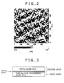
- Fig. 1 an AFM (atomic force microscopic) image of the first layer yielded in Production Example 37; and in Fig. 2 , an AFM image of the first layer yielded in Production Example 3.
- a first layer which is made of an Ag-based alloy of fine crystals having an average crystal grain diameter of 100 nm or less according to the invention, an effect of sealing pinholes in the second layer (concerned) is exhibited, so that a good result is obtained.
- the invention is useful for supplying a reflective film laminate having a reflectivity that is not easily deteriorated by the aggregation of Ag atoms in its Ag film.
Landscapes
- Chemical & Material Sciences (AREA)
- Engineering & Computer Science (AREA)
- Materials Engineering (AREA)
- Organic Chemistry (AREA)
- Physics & Mathematics (AREA)
- Metallurgy (AREA)
- Mechanical Engineering (AREA)
- General Physics & Mathematics (AREA)
- Chemical Kinetics & Catalysis (AREA)
- Optics & Photonics (AREA)
- General Engineering & Computer Science (AREA)
- Optical Elements Other Than Lenses (AREA)
- Physical Vapour Deposition (AREA)
- Laminated Bodies (AREA)
Applications Claiming Priority (2)
| Application Number | Priority Date | Filing Date | Title |
|---|---|---|---|
| JP2010013492 | 2010-01-25 | ||
| PCT/JP2011/051337 WO2011090207A1 (ja) | 2010-01-25 | 2011-01-25 | 反射膜積層体 |
Publications (2)
| Publication Number | Publication Date |
|---|---|
| EP2530495A1 true EP2530495A1 (de) | 2012-12-05 |
| EP2530495A4 EP2530495A4 (de) | 2013-08-28 |
Family
ID=44307008
Family Applications (1)
| Application Number | Title | Priority Date | Filing Date |
|---|---|---|---|
| EP11734813.6A Withdrawn EP2530495A4 (de) | 2010-01-25 | 2011-01-25 | Reflektive filmbeschichtung |
Country Status (5)
| Country | Link |
|---|---|
| US (1) | US20120287659A1 (de) |
| EP (1) | EP2530495A4 (de) |
| JP (1) | JP5719179B2 (de) |
| CN (1) | CN102687044B (de) |
| WO (1) | WO2011090207A1 (de) |
Families Citing this family (13)
| Publication number | Priority date | Publication date | Assignee | Title |
|---|---|---|---|---|
| EP2755819B1 (de) * | 2011-09-14 | 2016-09-14 | Xtalic Corporation | Silberlegierungsbechichtete Gegenstände |
| JP5860335B2 (ja) * | 2012-04-23 | 2016-02-16 | 株式会社神戸製鋼所 | 反射膜積層体およびその製造方法 |
| JP5867343B2 (ja) * | 2012-08-30 | 2016-02-24 | 豊田合成株式会社 | 灯具用リフレクタの製造方法 |
| JP5896889B2 (ja) * | 2012-12-07 | 2016-03-30 | 株式会社豊田自動織機 | 光学選択膜 |
| JP6197833B2 (ja) * | 2015-06-30 | 2017-09-20 | 株式会社豊田自動織機 | 太陽熱集熱管及び太陽熱発電装置 |
| JP2019035100A (ja) * | 2016-01-06 | 2019-03-07 | コニカミノルタ株式会社 | 反射膜の製造方法 |
| RU2623573C1 (ru) * | 2016-04-29 | 2017-06-27 | Федеральное государственное бюджетное образовательное учреждение высшего образования "Саратовский государственный технический университет имени Гагарина Ю.А." (СГТУ имени Гагарина Ю.А.) | Способ изготовления пленочного материала на основе смеси фаз VOx, где x=1,5-2,02 |
| CN109560290B (zh) * | 2018-12-26 | 2023-10-27 | 浙江锋源氢能科技有限公司 | 一种金属双极板及其制备方法以及燃料电池 |
| CN109560289B (zh) * | 2018-12-26 | 2023-11-28 | 浙江锋源氢能科技有限公司 | 一种金属双极板及其制备方法以及燃料电池 |
| CN111580305A (zh) * | 2020-05-13 | 2020-08-25 | Tcl华星光电技术有限公司 | 一种背光模组 |
| CN113571622B (zh) * | 2021-07-22 | 2022-08-23 | 厦门三安光电有限公司 | 发光二极管及其制备方法 |
| JP7344937B2 (ja) * | 2021-07-30 | 2023-09-14 | 日機装株式会社 | 半導体発光素子および半導体発光素子の製造方法 |
| US20230406761A1 (en) * | 2022-06-17 | 2023-12-21 | Apple Inc. | Systems With Infrared Reflective Coatings |
Family Cites Families (28)
| Publication number | Priority date | Publication date | Assignee | Title |
|---|---|---|---|---|
| JPH01279202A (ja) * | 1988-05-02 | 1989-11-09 | Mitsui Toatsu Chem Inc | 反射体 |
| JPH08234004A (ja) * | 1995-02-27 | 1996-09-13 | Canon Inc | 金属ミラーおよびその製造方法 |
| JP3734176B2 (ja) * | 1995-04-03 | 2006-01-11 | セイコーエプソン株式会社 | インクジェット記録用プリンタヘッドの製造方法及びアクチュエータの製造方法 |
| JP2000106017A (ja) | 1998-09-29 | 2000-04-11 | Koito Mfg Co Ltd | 車両用灯具 |
| US7513815B2 (en) * | 1999-12-23 | 2009-04-07 | General Electric Company | Optimal silicon dioxide protection layer thickness for silver lamp reflector |
| TWI243095B (en) * | 2001-04-24 | 2005-11-11 | Mitsui Chemicals Inc | Lamp reflector and reflector |
| JP4031285B2 (ja) * | 2001-04-24 | 2008-01-09 | 三井化学株式会社 | ランプリフレクターおよび反射体 |
| JP3908036B2 (ja) * | 2002-01-10 | 2007-04-25 | 株式会社小糸製作所 | 反射鏡製造方法及び反射鏡製造装置 |
| JP3993530B2 (ja) * | 2003-05-16 | 2007-10-17 | 株式会社神戸製鋼所 | Ag−Bi系合金スパッタリングターゲットおよびその製造方法 |
| KR20050001425A (ko) * | 2003-06-27 | 2005-01-06 | 아사히 가라스 가부시키가이샤 | 고반사경 |
| KR100931675B1 (ko) * | 2003-07-02 | 2009-12-16 | 삼성전자주식회사 | 확산 반사필름을 갖는 백라이트 어셈블리 |
| KR20060089214A (ko) * | 2003-09-26 | 2006-08-08 | 가부시키가이샤 후루야긴조쿠 | 은합금, 그 스퍼터링 타겟재 및 그 박막 |
| JP2005250229A (ja) * | 2004-03-05 | 2005-09-15 | Asahi Glass Co Ltd | 高反射鏡 |
| TWI325134B (en) * | 2004-04-21 | 2010-05-21 | Kobe Steel Ltd | Semi-reflective film and reflective film for optical information recording medium, optical information recording medium, and sputtering target |
| JP3907666B2 (ja) * | 2004-07-15 | 2007-04-18 | 株式会社神戸製鋼所 | レーザーマーキング用再生専用光情報記録媒体 |
| JP2006098856A (ja) * | 2004-09-30 | 2006-04-13 | Ulvac Japan Ltd | Ag系反射膜およびその作製方法 |
| JP4527624B2 (ja) * | 2005-07-22 | 2010-08-18 | 株式会社神戸製鋼所 | Ag合金反射膜を有する光情報媒体 |
| CN101008055A (zh) * | 2006-01-26 | 2007-08-01 | 恺锐科技股份有限公司 | 用于反射或半反射层的银合金 |
| JP2007248562A (ja) * | 2006-03-14 | 2007-09-27 | Shincron:Kk | 光学物品およびその製造方法 |
| US7833604B2 (en) * | 2006-12-01 | 2010-11-16 | Kobe Steel, Ltd. | Ag alloy reflective layer for optical information recording medium, optical information recording medium, and sputtering target for forming Ag alloy reflective layer for optical information recording medium |
| JP2008164768A (ja) * | 2006-12-27 | 2008-07-17 | Asahi Glass Co Ltd | 反射鏡 |
| JP5049417B2 (ja) * | 2007-02-07 | 2012-10-17 | スタンレー電気株式会社 | 車両用灯具のリフレクター |
| JP5144302B2 (ja) * | 2007-02-20 | 2013-02-13 | 株式会社神戸製鋼所 | 反射膜積層体 |
| JP5280777B2 (ja) * | 2007-09-25 | 2013-09-04 | 株式会社神戸製鋼所 | 反射膜積層体 |
| WO2009041529A1 (ja) * | 2007-09-25 | 2009-04-02 | Kabushiki Kaisha Kobe Seiko Sho | 反射膜、反射膜積層体、led、有機elディスプレイ及び有機el照明器具 |
| FI20070991L (fi) * | 2007-12-19 | 2009-06-20 | Beneq Oy | Lasituote, tuotteen käyttö ja valmistusmenetelmä |
| JP5503388B2 (ja) * | 2009-05-25 | 2014-05-28 | 株式会社神戸製鋼所 | Led用リードフレーム |
| JP2011164552A (ja) * | 2010-02-15 | 2011-08-25 | Osaka Univ | 電子部品、電子回路装置、および電子部品の製造方法 |
-
2011
- 2011-01-11 JP JP2011003458A patent/JP5719179B2/ja active Active
- 2011-01-25 CN CN201180004964.8A patent/CN102687044B/zh not_active Expired - Fee Related
- 2011-01-25 WO PCT/JP2011/051337 patent/WO2011090207A1/ja not_active Ceased
- 2011-01-25 US US13/522,820 patent/US20120287659A1/en not_active Abandoned
- 2011-01-25 EP EP11734813.6A patent/EP2530495A4/de not_active Withdrawn
Also Published As
| Publication number | Publication date |
|---|---|
| EP2530495A4 (de) | 2013-08-28 |
| JP2011170326A (ja) | 2011-09-01 |
| CN102687044B (zh) | 2014-11-05 |
| WO2011090207A1 (ja) | 2011-07-28 |
| JP5719179B2 (ja) | 2015-05-13 |
| CN102687044A (zh) | 2012-09-19 |
| US20120287659A1 (en) | 2012-11-15 |
Similar Documents
| Publication | Publication Date | Title |
|---|---|---|
| EP2530495A1 (de) | Reflektive filmbeschichtung | |
| CN101809467B (zh) | 反射膜、反射膜层叠体、led、有机el显示器及有机el照明器具 | |
| JP4009564B2 (ja) | リフレクター用Ag合金反射膜、及び、このAg合金反射膜を用いたリフレクター、並びに、このAg合金反射膜のAg合金薄膜の形成用のAg合金スパッタリングターゲット | |
| US7452604B2 (en) | Reflective Ag alloy film for reflectors and reflector provided with the same | |
| US7022384B2 (en) | Reflective film, reflection type liquid crystal display, and sputtering target for forming the reflective film | |
| TWI527919B (zh) | Ag alloy film for reflective electrode and reflective electrode | |
| US8603648B2 (en) | Reflective film laminate | |
| WO2004102231A1 (ja) | 反射体、その用途および反射体の製造方法 | |
| US9947429B2 (en) | Ag alloy film for reflecting electrode or wiring electrode, reflecting electrode or wiring electrode, and Ag alloy sputtering target | |
| JP5280777B2 (ja) | 反射膜積層体 | |
| JP5097031B2 (ja) | 反射膜、led、有機elディスプレイ及び有機el照明器具 | |
| JP2008190036A (ja) | 耐凝集性および耐硫化性に優れた反射膜 | |
| WO2006132417A1 (ja) | 反射率・透過率維持特性に優れた銀合金 | |
| WO2006132416A1 (ja) | 反射率・透過率維持特性に優れた銀合金 | |
| JP5144302B2 (ja) | 反射膜積層体 | |
| JP5860335B2 (ja) | 反射膜積層体およびその製造方法 | |
| JP2011032533A (ja) | 反射膜積層体 | |
| JP2010097065A (ja) | 反射体 |
Legal Events
| Date | Code | Title | Description |
|---|---|---|---|
| PUAI | Public reference made under article 153(3) epc to a published international application that has entered the european phase |
Free format text: ORIGINAL CODE: 0009012 |
|
| 17P | Request for examination filed |
Effective date: 20120809 |
|
| AK | Designated contracting states |
Kind code of ref document: A1 Designated state(s): AL AT BE BG CH CY CZ DE DK EE ES FI FR GB GR HR HU IE IS IT LI LT LU LV MC MK MT NL NO PL PT RO RS SE SI SK SM TR |
|
| DAX | Request for extension of the european patent (deleted) | ||
| A4 | Supplementary search report drawn up and despatched |
Effective date: 20130731 |
|
| RIC1 | Information provided on ipc code assigned before grant |
Ipc: C23C 14/14 20060101ALI20130723BHEP Ipc: B32B 15/01 20060101ALI20130723BHEP Ipc: G02B 5/08 20060101AFI20130723BHEP Ipc: F21V 7/22 20060101ALI20130723BHEP Ipc: B32B 15/04 20060101ALI20130723BHEP Ipc: C23C 14/58 20060101ALI20130723BHEP |
|
| STAA | Information on the status of an ep patent application or granted ep patent |
Free format text: STATUS: THE APPLICATION IS DEEMED TO BE WITHDRAWN |
|
| 18D | Application deemed to be withdrawn |
Effective date: 20140301 |