EP2530785A1 - Décharge de traction de câble et connecteur à fiche avec décharge de traction de câble - Google Patents
Décharge de traction de câble et connecteur à fiche avec décharge de traction de câble Download PDFInfo
- Publication number
- EP2530785A1 EP2530785A1 EP12002723A EP12002723A EP2530785A1 EP 2530785 A1 EP2530785 A1 EP 2530785A1 EP 12002723 A EP12002723 A EP 12002723A EP 12002723 A EP12002723 A EP 12002723A EP 2530785 A1 EP2530785 A1 EP 2530785A1
- Authority
- EP
- European Patent Office
- Prior art keywords
- cable
- strain relief
- crimping
- connector
- cable strain
- Prior art date
- Legal status (The legal status is an assumption and is not a legal conclusion. Google has not performed a legal analysis and makes no representation as to the accuracy of the status listed.)
- Granted
Links
- 238000002788 crimping Methods 0.000 claims abstract description 36
- 230000035515 penetration Effects 0.000 claims 1
- 210000002105 tongue Anatomy 0.000 description 3
- 239000004020 conductor Substances 0.000 description 2
- 210000004907 gland Anatomy 0.000 description 2
- 230000032683 aging Effects 0.000 description 1
- 238000004873 anchoring Methods 0.000 description 1
- 230000001419 dependent effect Effects 0.000 description 1
- 239000000835 fiber Substances 0.000 description 1
- 238000009413 insulation Methods 0.000 description 1
- 238000004519 manufacturing process Methods 0.000 description 1
- 239000007787 solid Substances 0.000 description 1
Images
Classifications
-
- H—ELECTRICITY
- H01—ELECTRIC ELEMENTS
- H01R—ELECTRICALLY-CONDUCTIVE CONNECTIONS; STRUCTURAL ASSOCIATIONS OF A PLURALITY OF MUTUALLY-INSULATED ELECTRICAL CONNECTING ELEMENTS; COUPLING DEVICES; CURRENT COLLECTORS
- H01R13/00—Details of coupling devices of the kinds covered by groups H01R12/70 or H01R24/00 - H01R33/00
- H01R13/58—Means for relieving strain on wire connection, e.g. cord grip, for avoiding loosening of connections between wires and terminals within a coupling device terminating a cable
- H01R13/5804—Means for relieving strain on wire connection, e.g. cord grip, for avoiding loosening of connections between wires and terminals within a coupling device terminating a cable comprising a separate cable clamping part
- H01R13/5808—Means for relieving strain on wire connection, e.g. cord grip, for avoiding loosening of connections between wires and terminals within a coupling device terminating a cable comprising a separate cable clamping part formed by a metallic element crimped around the cable
-
- H—ELECTRICITY
- H01—ELECTRIC ELEMENTS
- H01R—ELECTRICALLY-CONDUCTIVE CONNECTIONS; STRUCTURAL ASSOCIATIONS OF A PLURALITY OF MUTUALLY-INSULATED ELECTRICAL CONNECTING ELEMENTS; COUPLING DEVICES; CURRENT COLLECTORS
- H01R4/00—Electrically-conductive connections between two or more conductive members in direct contact, i.e. touching one another; Means for effecting or maintaining such contact; Electrically-conductive connections having two or more spaced connecting locations for conductors and using contact members penetrating insulation
- H01R4/10—Electrically-conductive connections between two or more conductive members in direct contact, i.e. touching one another; Means for effecting or maintaining such contact; Electrically-conductive connections having two or more spaced connecting locations for conductors and using contact members penetrating insulation effected solely by twisting, wrapping, bending, crimping, or other permanent deformation
- H01R4/18—Electrically-conductive connections between two or more conductive members in direct contact, i.e. touching one another; Means for effecting or maintaining such contact; Electrically-conductive connections having two or more spaced connecting locations for conductors and using contact members penetrating insulation effected solely by twisting, wrapping, bending, crimping, or other permanent deformation by crimping
- H01R4/20—Electrically-conductive connections between two or more conductive members in direct contact, i.e. touching one another; Means for effecting or maintaining such contact; Electrically-conductive connections having two or more spaced connecting locations for conductors and using contact members penetrating insulation effected solely by twisting, wrapping, bending, crimping, or other permanent deformation by crimping using a crimping sleeve
- H01R4/203—Electrically-conductive connections between two or more conductive members in direct contact, i.e. touching one another; Means for effecting or maintaining such contact; Electrically-conductive connections having two or more spaced connecting locations for conductors and using contact members penetrating insulation effected solely by twisting, wrapping, bending, crimping, or other permanent deformation by crimping using a crimping sleeve having an uneven wire-receiving surface to improve the contact
- H01R4/206—Electrically-conductive connections between two or more conductive members in direct contact, i.e. touching one another; Means for effecting or maintaining such contact; Electrically-conductive connections having two or more spaced connecting locations for conductors and using contact members penetrating insulation effected solely by twisting, wrapping, bending, crimping, or other permanent deformation by crimping using a crimping sleeve having an uneven wire-receiving surface to improve the contact with transversal grooves or threads
-
- H—ELECTRICITY
- H01—ELECTRIC ELEMENTS
- H01R—ELECTRICALLY-CONDUCTIVE CONNECTIONS; STRUCTURAL ASSOCIATIONS OF A PLURALITY OF MUTUALLY-INSULATED ELECTRICAL CONNECTING ELEMENTS; COUPLING DEVICES; CURRENT COLLECTORS
- H01R9/00—Structural associations of a plurality of mutually-insulated electrical connecting elements, e.g. terminal strips or terminal blocks; Terminals or binding posts mounted upon a base or in a case; Bases therefor
- H01R9/03—Connectors arranged to contact a plurality of the conductors of a multiconductor cable, e.g. tapping connections
- H01R9/05—Connectors arranged to contact a plurality of the conductors of a multiconductor cable, e.g. tapping connections for coaxial cables
- H01R9/0518—Connection to outer conductor by crimping or by crimping ferrule
-
- H—ELECTRICITY
- H01—ELECTRIC ELEMENTS
- H01R—ELECTRICALLY-CONDUCTIVE CONNECTIONS; STRUCTURAL ASSOCIATIONS OF A PLURALITY OF MUTUALLY-INSULATED ELECTRICAL CONNECTING ELEMENTS; COUPLING DEVICES; CURRENT COLLECTORS
- H01R13/00—Details of coupling devices of the kinds covered by groups H01R12/70 or H01R24/00 - H01R33/00
- H01R13/648—Protective earth or shield arrangements on coupling devices, e.g. anti-static shielding
- H01R13/658—High frequency shielding arrangements, e.g. against EMI [Electro-Magnetic Interference] or EMP [Electro-Magnetic Pulse]
- H01R13/6591—Specific features or arrangements of connection of shield to conductive members
- H01R13/65912—Specific features or arrangements of connection of shield to conductive members for shielded multiconductor cable
- H01R13/65914—Connection of shield to additional grounding conductors
-
- H—ELECTRICITY
- H01—ELECTRIC ELEMENTS
- H01R—ELECTRICALLY-CONDUCTIVE CONNECTIONS; STRUCTURAL ASSOCIATIONS OF A PLURALITY OF MUTUALLY-INSULATED ELECTRICAL CONNECTING ELEMENTS; COUPLING DEVICES; CURRENT COLLECTORS
- H01R4/00—Electrically-conductive connections between two or more conductive members in direct contact, i.e. touching one another; Means for effecting or maintaining such contact; Electrically-conductive connections having two or more spaced connecting locations for conductors and using contact members penetrating insulation
- H01R4/10—Electrically-conductive connections between two or more conductive members in direct contact, i.e. touching one another; Means for effecting or maintaining such contact; Electrically-conductive connections having two or more spaced connecting locations for conductors and using contact members penetrating insulation effected solely by twisting, wrapping, bending, crimping, or other permanent deformation
- H01R4/18—Electrically-conductive connections between two or more conductive members in direct contact, i.e. touching one another; Means for effecting or maintaining such contact; Electrically-conductive connections having two or more spaced connecting locations for conductors and using contact members penetrating insulation effected solely by twisting, wrapping, bending, crimping, or other permanent deformation by crimping
- H01R4/188—Electrically-conductive connections between two or more conductive members in direct contact, i.e. touching one another; Means for effecting or maintaining such contact; Electrically-conductive connections having two or more spaced connecting locations for conductors and using contact members penetrating insulation effected solely by twisting, wrapping, bending, crimping, or other permanent deformation by crimping having an uneven wire-receiving surface to improve the contact
Definitions
- the present invention relates to a cable strain relief according to the preamble of claim 1.
- a cable strain relief is a connector that is to be coupled to the outer circumference of a cable and allows forces acting in the longitudinal direction of the cable, i. H. axial forces transmitted through the cable to an external structure.
- a cable typically contains a plurality of individual insulated conductors, which are also covered with a braided shield, it must be ensured that the cable or conductors are not torn out of the connection arrangement.
- a known in the art type of cable strain relief has z.
- B two tubular parts having cooperating conical surfaces. An interior portion formed slotted, wherein the slot typically extends axially from one end to the proximate other end, such that axially extending tabs are formed.
- the US 5,180,316 A discloses a generally tubular, longitudinally split connector body which is crimped at one of its ends about an exposed shield of a cable. In this embodiment, attempts are made by means of a crimping and thus a mechanical deformation of a connecting body to achieve a solid and therefore permanent connection with the cable sheath.
- a disadvantage of this type of connection solution is that a large-scale investment of the crimp inner sleeve leads to the cable jacket that the plastic flows away and a permanent connection is not guaranteed or at least problems may occur in the application.
- Object of the present invention is therefore to provide a strain relief, a cable, in particular with a cable shield, in particular large cable cross-sections, ie cross sections> 30 mm 2 can be attached using a simple tool and a permanent and tight connection with the cable manufacture.
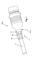
- Fig. 1 shows an embodiment of a connector 100 according to the invention with a cable strain relief according to the invention 1.
- the connector 100 is shown here as a circular connector, which is connected to a cable 2, here a shielded cable 2 by means of Jardinzugentlastung 1.
- the connector 100 has a holding portion 101, which is connected to the connecting portion 4 of the cable strain relief 1.
- the connecting portion 4 in the present embodiment an inner connecting portion which can be secured, for example, with a thread on the holding portion 101 of the connector 100.
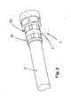
- the cable strain relief 1 comprises two crimping sections, specifically a first crimping section 30 and a second crimping section 40 spaced therefrom.
- the Fig. 1 and Fig. 2 show the crimped state of the crimping sleeve 3 of the cable strain relief.
- An essential part of the cable strain relief 1 is therefore the cylindrically shaped crimp barrel 3 or tubular crimp barrel 3.
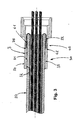
- the cable 2 is introduced with its cable sheath 20 and the folded back braid 22, as shown in Fig. 3 is apparent.
- crimp sleeve 3 is shown in not yet crimped state, so that the outer sheath 34 is formed contourless.
- a cable engagement 35 On the inner jacket 32 of the crimping sleeve 3, in the region of the first crimping section 30, there is a cable engagement 35, which in the present exemplary embodiment is designed as an inner circumferential annular section 31.
- the inner circumferential ring portion 31 may be completely closed circumferentially or sequentially interrupted on the inner shell 32 may be arranged.
- the annular portion 31 is formed tip-shaped or with a sharp contour for engagement in the cable sheath.
- In cross-section results in a substantially triangular pointed shape, which is preferably tuned in its geometry to the hardness of the cable sheath 20.
- the left and right sections adjacent to the crimping section are crimped with a crimping tool so that the ring section 31 penetrates into the cable sheath 20 and digs there.
- the second crimping portion 40 adjacent to the first crimping portion 30 is different from the former.
- the second crimping section 40 consists of two separate means, namely an annular groove 42 formed on the inner jacket 32 and a ring element 41 corresponding to this groove.
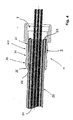
- the ring member 41 is mounted between the cable sheath 20 and the folded back at the end of the cable 2 cable shield namely the screen braid 22. So then the crimp barrel, as in Fig. 3 shown, pushed over the cable sheath 20, as far as until the annular groove 42 is located above or around the ring member 41. In this position, the crimping sleeve 3 is crimped by means of a crimping tool so that the in Fig. 4 illustrated contour is formed.
- the ring portion 31 penetrates into the cable sheath 20, while the areas are compressed around the second crimping portion 40 and crimped onto the cable sheath, that the less crimped crimping portion 40 is pressed into the ring member 41 and between the shield braid 22 is received.
- the crimped sleeve consists of three holding portions 36, which are each interrupted by one of the crimping portions 30, 40.
- the holding portions of the crimping sleeve 30 are pressed in the compressed and deformed state on the cable sheath 20 so that they connect the cable strain relief 1 fixed to the cable sheath.
- the connection as described above is made with the cable sheath and the cable shield.
- a cable strain relief 1 could similarly be provided for unshielded cables having two identical or similar crimping portions 30 with cable engagements 35.
- the ring portion 31 is advantageously designed so that at its the cable sheath 20 facing crest line 33 a tip or more tips or teeth are arranged, preferably as in Fig. 4 shown, the crest line is formed circumferentially as a pointed contour.
Landscapes
- Details Of Connecting Devices For Male And Female Coupling (AREA)
Applications Claiming Priority (1)
| Application Number | Priority Date | Filing Date | Title |
|---|---|---|---|
| DE202011101380U DE202011101380U1 (de) | 2011-06-01 | 2011-06-01 | Kabelzugentlastung und Steckverbinder mit Kabelzugentlastung |
Publications (2)
| Publication Number | Publication Date |
|---|---|
| EP2530785A1 true EP2530785A1 (fr) | 2012-12-05 |
| EP2530785B1 EP2530785B1 (fr) | 2018-04-04 |
Family
ID=44586439
Family Applications (1)
| Application Number | Title | Priority Date | Filing Date |
|---|---|---|---|
| EP12002723.0A Not-in-force EP2530785B1 (fr) | 2011-06-01 | 2012-04-19 | Connecteur à fiche avec décharge de traction de câble |
Country Status (2)
| Country | Link |
|---|---|
| EP (1) | EP2530785B1 (fr) |
| DE (1) | DE202011101380U1 (fr) |
Cited By (2)
| Publication number | Priority date | Publication date | Assignee | Title |
|---|---|---|---|---|
| CN108346938A (zh) * | 2018-04-18 | 2018-07-31 | 昆山合真和光电科技有限公司 | 带有梅花环的小型可插拔线缆连接器 |
| EP4693761A1 (fr) * | 2024-08-07 | 2026-02-11 | Aptiv Technologies AG | Serre-câble à blindage de borne hs |
Families Citing this family (5)
| Publication number | Priority date | Publication date | Assignee | Title |
|---|---|---|---|---|
| DE102013201531B4 (de) * | 2013-01-30 | 2017-02-09 | Leoni Bordnetz-Systeme Gmbh | Elektrische Kontaktverbindung |
| DE102014006061B4 (de) | 2014-04-25 | 2019-01-17 | Jenny Science Ag | Elektrisch leitendes Gehäuse mit Kabelzugentlastung und Schirmanbindung |
| HUE045125T2 (hu) * | 2016-05-04 | 2019-12-30 | Md Elektronik Gmbh | Kábel |
| DE102017218848A1 (de) * | 2017-10-23 | 2019-04-25 | Leoni Kabel Gmbh | Steckererweiterung für eine Steckverbindung |
| DE102018000140B4 (de) * | 2018-01-10 | 2019-10-02 | Sumitomo Wiring Systems, Ltd. | Abgeschirmter Kabelbaum und Verfahren zum Herstellen eines abgeschirmten Kabelbaums |
Citations (6)
| Publication number | Priority date | Publication date | Assignee | Title |
|---|---|---|---|---|
| US4684201A (en) * | 1985-06-28 | 1987-08-04 | Allied Corporation | One-piece crimp-type connector and method for terminating a coaxial cable |
| US5180316A (en) | 1991-03-25 | 1993-01-19 | Molex Incorporated | Shielded electrical connector |
| US6087584A (en) * | 1998-06-30 | 2000-07-11 | Lucent Technologies Inc. | Tubular cable grounding mechanism |
| US6089913A (en) * | 1996-11-12 | 2000-07-18 | Holliday; Randall A. | End connector and crimping tool for coaxial cable |
| EP1168506A2 (fr) * | 2000-06-20 | 2002-01-02 | Autonetworks Technologies, Ltd. | Structure de borne de connexion pour un câble blindé |
| US20030068924A1 (en) * | 1997-08-02 | 2003-04-10 | Montena Noah P. | Connector and method of operation |
Family Cites Families (2)
| Publication number | Priority date | Publication date | Assignee | Title |
|---|---|---|---|---|
| DE202008015165U1 (de) * | 2008-11-16 | 2010-04-08 | Few Fahrzeugelektrikwerk Gmbh & Co. Kg | Aderendhülse |
| JP2010146739A (ja) * | 2008-12-16 | 2010-07-01 | Sumitomo Wiring Syst Ltd | 電線接続スリーブ、電線接続スリーブの製造方法、電線接続スリーブが予め圧着されたリペア電線、および電線の接続方法 |
-
2011
- 2011-06-01 DE DE202011101380U patent/DE202011101380U1/de not_active Expired - Lifetime
-
2012
- 2012-04-19 EP EP12002723.0A patent/EP2530785B1/fr not_active Not-in-force
Patent Citations (6)
| Publication number | Priority date | Publication date | Assignee | Title |
|---|---|---|---|---|
| US4684201A (en) * | 1985-06-28 | 1987-08-04 | Allied Corporation | One-piece crimp-type connector and method for terminating a coaxial cable |
| US5180316A (en) | 1991-03-25 | 1993-01-19 | Molex Incorporated | Shielded electrical connector |
| US6089913A (en) * | 1996-11-12 | 2000-07-18 | Holliday; Randall A. | End connector and crimping tool for coaxial cable |
| US20030068924A1 (en) * | 1997-08-02 | 2003-04-10 | Montena Noah P. | Connector and method of operation |
| US6087584A (en) * | 1998-06-30 | 2000-07-11 | Lucent Technologies Inc. | Tubular cable grounding mechanism |
| EP1168506A2 (fr) * | 2000-06-20 | 2002-01-02 | Autonetworks Technologies, Ltd. | Structure de borne de connexion pour un câble blindé |
Cited By (2)
| Publication number | Priority date | Publication date | Assignee | Title |
|---|---|---|---|---|
| CN108346938A (zh) * | 2018-04-18 | 2018-07-31 | 昆山合真和光电科技有限公司 | 带有梅花环的小型可插拔线缆连接器 |
| EP4693761A1 (fr) * | 2024-08-07 | 2026-02-11 | Aptiv Technologies AG | Serre-câble à blindage de borne hs |
Also Published As
| Publication number | Publication date |
|---|---|
| DE202011101380U1 (de) | 2011-08-08 |
| EP2530785B1 (fr) | 2018-04-04 |
Similar Documents
| Publication | Publication Date | Title |
|---|---|---|
| DE102007053459B4 (de) | Verarbeitungsanordnung für einen Abschirmendabschnitt | |
| EP2530785B1 (fr) | Connecteur à fiche avec décharge de traction de câble | |
| DE102010017265B4 (de) | Kabelanschlusseinrichtung und Verfahren zum Anschließen eines Kabels an eine Kabelanschlusseinrichtung | |
| EP2365586B1 (fr) | Connecteur à fiches câblé, notamment connecteur à fiches câblé multipolaire | |
| DE102009010492B3 (de) | Kabelordnender Einsatz für Steckverbinder | |
| EP2456013B1 (fr) | Connexion par sertissage à complémentarité de forme et de force pour un connecteur à fiche coaxial et outil de sertissage associé | |
| WO2015197776A1 (fr) | Élément de connexion de câble | |
| DE202016104726U1 (de) | Federkontaktstift mit einer Hülse | |
| DE102016105465A1 (de) | Mit einem verdrillte Adernpaare aufweisenden Kabel verbundener Steckverbinder | |
| DE102017126185B4 (de) | Elektrisches Kontaktelement | |
| DE102019132495A1 (de) | Abschirmungsanordnung und Verfahren zur Montage einer Abschirmungsanordnung | |
| EP2764387A1 (fr) | Système de décharge de traction pour câbles, en particulier pour câbles optiques | |
| DE102020133781A1 (de) | Zugentlastung für einen an einer geschirmten Leitung angeordneten Steckverbinder | |
| AT515474B1 (de) | Vorrichtung zum Einziehen von Kabeln | |
| DE3137262C2 (de) | Elektrischer Steckverbinder für ein Zugentlastungsseil enthaltende Kabel | |
| DE102015220685B4 (de) | Zugentlastungselement für eine Leitung, Aufnahmeeinrichtung, Zugentlastungsvorrichtung und Gehäuse | |
| DE102005041892A1 (de) | Elektrischer Verbinder | |
| DE102017218825B4 (de) | Verfahren zur elektrischen Kontaktierung einer elektrischen Maschine sowie elektrische Maschine mit dieser Kontaktierung | |
| DE102016108311B3 (de) | Verfahren zur Herstellung einer Kabelzugentlastung und Steckverbinder mit dieser Kabelzugentlastung | |
| DE2744351C2 (de) | Hochspannungs-Anschlußstecker mit Drehsicherung und Zugentlastung des angeschlossenen Kabelanschlusses | |
| DE29711253U1 (de) | Vorrichtung zur Kontaktierung des Schirmgeflechts eines elektrischen Kabels mit angepaßtem Steckverbinder und aufrastbarer Abdeckkappe | |
| DE102013014200A1 (de) | Kontaktelement mit einem klemmenden Anschluss für Litzenleiter | |
| DE60000884T2 (de) | Vorrichtung zum Abdichten einer Verbindung eines flachen Geflechts | |
| DE102017126757A1 (de) | Elektrischer Steckverbinder | |
| DE202016106269U1 (de) | Kontaktelement mit einem klemmenden Anschluss für Litzenleiter |
Legal Events
| Date | Code | Title | Description |
|---|---|---|---|
| PUAI | Public reference made under article 153(3) epc to a published international application that has entered the european phase |
Free format text: ORIGINAL CODE: 0009012 |
|
| 17P | Request for examination filed |
Effective date: 20120419 |
|
| AK | Designated contracting states |
Kind code of ref document: A1 Designated state(s): AL AT BE BG CH CY CZ DE DK EE ES FI FR GB GR HR HU IE IS IT LI LT LU LV MC MK MT NL NO PL PT RO RS SE SI SK SM TR |
|
| AX | Request for extension of the european patent |
Extension state: BA ME |
|
| RBV | Designated contracting states (corrected) |
Designated state(s): AL AT BE BG CH CY CZ DE DK EE ES FI FR GB GR HR HU IE IS IT LI LT LU LV MC MK MT NL NO PL PT RO RS SE SI SK SM TR |
|
| 17Q | First examination report despatched |
Effective date: 20160119 |
|
| REG | Reference to a national code |
Ref country code: DE Ref legal event code: R079 Ref document number: 502012012453 Country of ref document: DE Free format text: PREVIOUS MAIN CLASS: H01R0009050000 Ipc: H01R0004200000 |
|
| GRAP | Despatch of communication of intention to grant a patent |
Free format text: ORIGINAL CODE: EPIDOSNIGR1 |
|
| RIC1 | Information provided on ipc code assigned before grant |
Ipc: H01R 9/05 20060101ALI20170905BHEP Ipc: H01R 4/20 20060101AFI20170905BHEP Ipc: H01R 9/03 20060101ALI20170905BHEP Ipc: H01R 13/58 20060101ALI20170905BHEP Ipc: H01R 4/18 20060101ALI20170905BHEP |
|
| INTG | Intention to grant announced |
Effective date: 20171010 |
|
| GRAS | Grant fee paid |
Free format text: ORIGINAL CODE: EPIDOSNIGR3 |
|
| GRAA | (expected) grant |
Free format text: ORIGINAL CODE: 0009210 |
|
| AK | Designated contracting states |
Kind code of ref document: B1 Designated state(s): AL AT BE BG CH CY CZ DE DK EE ES FI FR GB GR HR HU IE IS IT LI LT LU LV MC MK MT NL NO PL PT RO RS SE SI SK SM TR |
|
| REG | Reference to a national code |
Ref country code: GB Ref legal event code: FG4D Free format text: NOT ENGLISH |
|
| REG | Reference to a national code |
Ref country code: CH Ref legal event code: EP |
|
| REG | Reference to a national code |
Ref country code: AT Ref legal event code: REF Ref document number: 986551 Country of ref document: AT Kind code of ref document: T Effective date: 20180415 |
|
| REG | Reference to a national code |
Ref country code: IE Ref legal event code: FG4D Free format text: LANGUAGE OF EP DOCUMENT: GERMAN |
|
| REG | Reference to a national code |
Ref country code: DE Ref legal event code: R096 Ref document number: 502012012453 Country of ref document: DE |
|
| REG | Reference to a national code |
Ref country code: FR Ref legal event code: PLFP Year of fee payment: 7 |
|
| REG | Reference to a national code |
Ref country code: NL Ref legal event code: MP Effective date: 20180404 |
|
| REG | Reference to a national code |
Ref country code: LT Ref legal event code: MG4D |
|
| PG25 | Lapsed in a contracting state [announced via postgrant information from national office to epo] |
Ref country code: NL Free format text: LAPSE BECAUSE OF FAILURE TO SUBMIT A TRANSLATION OF THE DESCRIPTION OR TO PAY THE FEE WITHIN THE PRESCRIBED TIME-LIMIT Effective date: 20180404 |
|
| PG25 | Lapsed in a contracting state [announced via postgrant information from national office to epo] |
Ref country code: AL Free format text: LAPSE BECAUSE OF FAILURE TO SUBMIT A TRANSLATION OF THE DESCRIPTION OR TO PAY THE FEE WITHIN THE PRESCRIBED TIME-LIMIT Effective date: 20180404 Ref country code: ES Free format text: LAPSE BECAUSE OF FAILURE TO SUBMIT A TRANSLATION OF THE DESCRIPTION OR TO PAY THE FEE WITHIN THE PRESCRIBED TIME-LIMIT Effective date: 20180404 Ref country code: NO Free format text: LAPSE BECAUSE OF FAILURE TO SUBMIT A TRANSLATION OF THE DESCRIPTION OR TO PAY THE FEE WITHIN THE PRESCRIBED TIME-LIMIT Effective date: 20180704 Ref country code: LT Free format text: LAPSE BECAUSE OF FAILURE TO SUBMIT A TRANSLATION OF THE DESCRIPTION OR TO PAY THE FEE WITHIN THE PRESCRIBED TIME-LIMIT Effective date: 20180404 Ref country code: PL Free format text: LAPSE BECAUSE OF FAILURE TO SUBMIT A TRANSLATION OF THE DESCRIPTION OR TO PAY THE FEE WITHIN THE PRESCRIBED TIME-LIMIT Effective date: 20180404 Ref country code: SE Free format text: LAPSE BECAUSE OF FAILURE TO SUBMIT A TRANSLATION OF THE DESCRIPTION OR TO PAY THE FEE WITHIN THE PRESCRIBED TIME-LIMIT Effective date: 20180404 Ref country code: FI Free format text: LAPSE BECAUSE OF FAILURE TO SUBMIT A TRANSLATION OF THE DESCRIPTION OR TO PAY THE FEE WITHIN THE PRESCRIBED TIME-LIMIT Effective date: 20180404 Ref country code: BG Free format text: LAPSE BECAUSE OF FAILURE TO SUBMIT A TRANSLATION OF THE DESCRIPTION OR TO PAY THE FEE WITHIN THE PRESCRIBED TIME-LIMIT Effective date: 20180704 |
|
| PG25 | Lapsed in a contracting state [announced via postgrant information from national office to epo] |
Ref country code: RS Free format text: LAPSE BECAUSE OF FAILURE TO SUBMIT A TRANSLATION OF THE DESCRIPTION OR TO PAY THE FEE WITHIN THE PRESCRIBED TIME-LIMIT Effective date: 20180404 Ref country code: LV Free format text: LAPSE BECAUSE OF FAILURE TO SUBMIT A TRANSLATION OF THE DESCRIPTION OR TO PAY THE FEE WITHIN THE PRESCRIBED TIME-LIMIT Effective date: 20180404 Ref country code: HR Free format text: LAPSE BECAUSE OF FAILURE TO SUBMIT A TRANSLATION OF THE DESCRIPTION OR TO PAY THE FEE WITHIN THE PRESCRIBED TIME-LIMIT Effective date: 20180404 Ref country code: GR Free format text: LAPSE BECAUSE OF FAILURE TO SUBMIT A TRANSLATION OF THE DESCRIPTION OR TO PAY THE FEE WITHIN THE PRESCRIBED TIME-LIMIT Effective date: 20180705 |
|
| REG | Reference to a national code |
Ref country code: CH Ref legal event code: PL |
|
| REG | Reference to a national code |
Ref country code: BE Ref legal event code: MM Effective date: 20180430 |
|
| PG25 | Lapsed in a contracting state [announced via postgrant information from national office to epo] |
Ref country code: PT Free format text: LAPSE BECAUSE OF FAILURE TO SUBMIT A TRANSLATION OF THE DESCRIPTION OR TO PAY THE FEE WITHIN THE PRESCRIBED TIME-LIMIT Effective date: 20180806 |
|
| REG | Reference to a national code |
Ref country code: DE Ref legal event code: R097 Ref document number: 502012012453 Country of ref document: DE |
|
| REG | Reference to a national code |
Ref country code: IE Ref legal event code: MM4A |
|
| PG25 | Lapsed in a contracting state [announced via postgrant information from national office to epo] |
Ref country code: SK Free format text: LAPSE BECAUSE OF FAILURE TO SUBMIT A TRANSLATION OF THE DESCRIPTION OR TO PAY THE FEE WITHIN THE PRESCRIBED TIME-LIMIT Effective date: 20180404 Ref country code: RO Free format text: LAPSE BECAUSE OF FAILURE TO SUBMIT A TRANSLATION OF THE DESCRIPTION OR TO PAY THE FEE WITHIN THE PRESCRIBED TIME-LIMIT Effective date: 20180404 Ref country code: LU Free format text: LAPSE BECAUSE OF NON-PAYMENT OF DUE FEES Effective date: 20180419 Ref country code: EE Free format text: LAPSE BECAUSE OF FAILURE TO SUBMIT A TRANSLATION OF THE DESCRIPTION OR TO PAY THE FEE WITHIN THE PRESCRIBED TIME-LIMIT Effective date: 20180404 Ref country code: DK Free format text: LAPSE BECAUSE OF FAILURE TO SUBMIT A TRANSLATION OF THE DESCRIPTION OR TO PAY THE FEE WITHIN THE PRESCRIBED TIME-LIMIT Effective date: 20180404 Ref country code: MC Free format text: LAPSE BECAUSE OF FAILURE TO SUBMIT A TRANSLATION OF THE DESCRIPTION OR TO PAY THE FEE WITHIN THE PRESCRIBED TIME-LIMIT Effective date: 20180404 Ref country code: CZ Free format text: LAPSE BECAUSE OF FAILURE TO SUBMIT A TRANSLATION OF THE DESCRIPTION OR TO PAY THE FEE WITHIN THE PRESCRIBED TIME-LIMIT Effective date: 20180404 |
|
| PLBE | No opposition filed within time limit |
Free format text: ORIGINAL CODE: 0009261 |
|
| STAA | Information on the status of an ep patent application or granted ep patent |
Free format text: STATUS: NO OPPOSITION FILED WITHIN TIME LIMIT |
|
| PG25 | Lapsed in a contracting state [announced via postgrant information from national office to epo] |
Ref country code: LI Free format text: LAPSE BECAUSE OF NON-PAYMENT OF DUE FEES Effective date: 20180430 Ref country code: SM Free format text: LAPSE BECAUSE OF FAILURE TO SUBMIT A TRANSLATION OF THE DESCRIPTION OR TO PAY THE FEE WITHIN THE PRESCRIBED TIME-LIMIT Effective date: 20180404 Ref country code: BE Free format text: LAPSE BECAUSE OF NON-PAYMENT OF DUE FEES Effective date: 20180430 Ref country code: CH Free format text: LAPSE BECAUSE OF NON-PAYMENT OF DUE FEES Effective date: 20180430 |
|
| 26N | No opposition filed |
Effective date: 20190107 |
|
| PG25 | Lapsed in a contracting state [announced via postgrant information from national office to epo] |
Ref country code: IE Free format text: LAPSE BECAUSE OF NON-PAYMENT OF DUE FEES Effective date: 20180419 |
|
| PG25 | Lapsed in a contracting state [announced via postgrant information from national office to epo] |
Ref country code: SI Free format text: LAPSE BECAUSE OF FAILURE TO SUBMIT A TRANSLATION OF THE DESCRIPTION OR TO PAY THE FEE WITHIN THE PRESCRIBED TIME-LIMIT Effective date: 20180404 |
|
| REG | Reference to a national code |
Ref country code: AT Ref legal event code: MM01 Ref document number: 986551 Country of ref document: AT Kind code of ref document: T Effective date: 20180419 |
|
| PG25 | Lapsed in a contracting state [announced via postgrant information from national office to epo] |
Ref country code: AT Free format text: LAPSE BECAUSE OF NON-PAYMENT OF DUE FEES Effective date: 20180419 |
|
| PG25 | Lapsed in a contracting state [announced via postgrant information from national office to epo] |
Ref country code: MT Free format text: LAPSE BECAUSE OF FAILURE TO SUBMIT A TRANSLATION OF THE DESCRIPTION OR TO PAY THE FEE WITHIN THE PRESCRIBED TIME-LIMIT Effective date: 20180404 |
|
| PG25 | Lapsed in a contracting state [announced via postgrant information from national office to epo] |
Ref country code: TR Free format text: LAPSE BECAUSE OF FAILURE TO SUBMIT A TRANSLATION OF THE DESCRIPTION OR TO PAY THE FEE WITHIN THE PRESCRIBED TIME-LIMIT Effective date: 20180404 |
|
| PG25 | Lapsed in a contracting state [announced via postgrant information from national office to epo] |
Ref country code: HU Free format text: LAPSE BECAUSE OF FAILURE TO SUBMIT A TRANSLATION OF THE DESCRIPTION OR TO PAY THE FEE WITHIN THE PRESCRIBED TIME-LIMIT; INVALID AB INITIO Effective date: 20120419 |
|
| PG25 | Lapsed in a contracting state [announced via postgrant information from national office to epo] |
Ref country code: CY Free format text: LAPSE BECAUSE OF FAILURE TO SUBMIT A TRANSLATION OF THE DESCRIPTION OR TO PAY THE FEE WITHIN THE PRESCRIBED TIME-LIMIT Effective date: 20180404 Ref country code: MK Free format text: LAPSE BECAUSE OF NON-PAYMENT OF DUE FEES Effective date: 20180404 |
|
| PG25 | Lapsed in a contracting state [announced via postgrant information from national office to epo] |
Ref country code: IS Free format text: LAPSE BECAUSE OF FAILURE TO SUBMIT A TRANSLATION OF THE DESCRIPTION OR TO PAY THE FEE WITHIN THE PRESCRIBED TIME-LIMIT Effective date: 20180804 |
|
| P01 | Opt-out of the competence of the unified patent court (upc) registered |
Effective date: 20230613 |
|
| PGFP | Annual fee paid to national office [announced via postgrant information from national office to epo] |
Ref country code: IT Payment date: 20230428 Year of fee payment: 12 Ref country code: FR Payment date: 20230417 Year of fee payment: 12 Ref country code: DE Payment date: 20230418 Year of fee payment: 12 |
|
| PGFP | Annual fee paid to national office [announced via postgrant information from national office to epo] |
Ref country code: GB Payment date: 20230420 Year of fee payment: 12 |
|
| REG | Reference to a national code |
Ref country code: DE Ref legal event code: R119 Ref document number: 502012012453 Country of ref document: DE |
|
| GBPC | Gb: european patent ceased through non-payment of renewal fee |
Effective date: 20240419 |
|
| PG25 | Lapsed in a contracting state [announced via postgrant information from national office to epo] |
Ref country code: DE Free format text: LAPSE BECAUSE OF NON-PAYMENT OF DUE FEES Effective date: 20241105 |
|
| PG25 | Lapsed in a contracting state [announced via postgrant information from national office to epo] |
Ref country code: GB Free format text: LAPSE BECAUSE OF NON-PAYMENT OF DUE FEES Effective date: 20240419 |
|
| PG25 | Lapsed in a contracting state [announced via postgrant information from national office to epo] |
Ref country code: FR Free format text: LAPSE BECAUSE OF NON-PAYMENT OF DUE FEES Effective date: 20240430 |
|
| PG25 | Lapsed in a contracting state [announced via postgrant information from national office to epo] |
Ref country code: GB Free format text: LAPSE BECAUSE OF NON-PAYMENT OF DUE FEES Effective date: 20240419 Ref country code: FR Free format text: LAPSE BECAUSE OF NON-PAYMENT OF DUE FEES Effective date: 20240430 Ref country code: DE Free format text: LAPSE BECAUSE OF NON-PAYMENT OF DUE FEES Effective date: 20241105 |
|
| PG25 | Lapsed in a contracting state [announced via postgrant information from national office to epo] |
Ref country code: IT Free format text: LAPSE BECAUSE OF NON-PAYMENT OF DUE FEES Effective date: 20240419 |