EP2530820A1 - Agencement destiné à orienter du courant et doté d'un onduleur - Google Patents
Agencement destiné à orienter du courant et doté d'un onduleur Download PDFInfo
- Publication number
- EP2530820A1 EP2530820A1 EP11168490A EP11168490A EP2530820A1 EP 2530820 A1 EP2530820 A1 EP 2530820A1 EP 11168490 A EP11168490 A EP 11168490A EP 11168490 A EP11168490 A EP 11168490A EP 2530820 A1 EP2530820 A1 EP 2530820A1
- Authority
- EP
- European Patent Office
- Prior art keywords
- terminal
- current transformer
- output
- inverter
- current
- Prior art date
- Legal status (The legal status is an assumption and is not a legal conclusion. Google has not performed a legal analysis and makes no representation as to the accuracy of the status listed.)
- Withdrawn
Links
- 239000003990 capacitor Substances 0.000 claims abstract description 44
- 230000005540 biological transmission Effects 0.000 claims abstract description 6
- 238000001914 filtration Methods 0.000 claims abstract description 4
- 238000006243 chemical reaction Methods 0.000 claims description 12
- 238000004804 winding Methods 0.000 claims description 7
- 239000002184 metal Substances 0.000 claims description 6
- 229910052751 metal Inorganic materials 0.000 claims description 6
- RYGMFSIKBFXOCR-UHFFFAOYSA-N Copper Chemical compound [Cu] RYGMFSIKBFXOCR-UHFFFAOYSA-N 0.000 claims description 3
- 229910052802 copper Inorganic materials 0.000 claims description 3
- 239000010949 copper Substances 0.000 claims description 3
- 230000005611 electricity Effects 0.000 claims description 2
- XUIMIQQOPSSXEZ-UHFFFAOYSA-N Silicon Chemical group [Si] XUIMIQQOPSSXEZ-UHFFFAOYSA-N 0.000 description 9
- 229910052710 silicon Inorganic materials 0.000 description 9
- 239000010703 silicon Substances 0.000 description 9
- 239000004020 conductor Substances 0.000 description 8
- 230000002500 effect on skin Effects 0.000 description 5
- 230000007935 neutral effect Effects 0.000 description 5
- 238000010276 construction Methods 0.000 description 3
- 230000000694 effects Effects 0.000 description 3
- 238000004519 manufacturing process Methods 0.000 description 2
- 238000000034 method Methods 0.000 description 2
- 229910021420 polycrystalline silicon Inorganic materials 0.000 description 2
- 229920005591 polysilicon Polymers 0.000 description 2
- 230000008021 deposition Effects 0.000 description 1
- 238000009826 distribution Methods 0.000 description 1
- 238000009429 electrical wiring Methods 0.000 description 1
- 230000004907 flux Effects 0.000 description 1
- 238000010438 heat treatment Methods 0.000 description 1
- 238000003475 lamination Methods 0.000 description 1
- 230000010363 phase shift Effects 0.000 description 1
- 238000007740 vapor deposition Methods 0.000 description 1
Images


Classifications
-
- H—ELECTRICITY
- H02—GENERATION; CONVERSION OR DISTRIBUTION OF ELECTRIC POWER
- H02M—APPARATUS FOR CONVERSION BETWEEN AC AND AC, BETWEEN AC AND DC, OR BETWEEN DC AND DC, AND FOR USE WITH MAINS OR SIMILAR POWER SUPPLY SYSTEMS; CONVERSION OF DC OR AC INPUT POWER INTO SURGE OUTPUT POWER; CONTROL OR REGULATION THEREOF
- H02M7/00—Conversion of AC power input into DC power output; Conversion of DC power input into AC power output
- H02M7/003—Constructional details, e.g. physical layout, assembly, wiring or busbar connections
-
- G—PHYSICS
- G05—CONTROLLING; REGULATING
- G05F—SYSTEMS FOR REGULATING ELECTRIC OR MAGNETIC VARIABLES
- G05F1/00—Automatic systems in which deviations of an electric quantity from one or more predetermined values are detected at the output of the system and fed back to a device within the system to restore the detected quantity to its predetermined value or values, i.e. retroactive systems
- G05F1/10—Regulating voltage or current
Definitions
- the present invention relates to an arrangement for the conversion of electricity.
- a power supply arrangement which is suitable and arranged for the deposition of silicon in a reactor according to the Siemens method.
- the silicon thin rods or silicon rods, on which the silicon is to be deposited are supplied with a low frequency having a frequency of about 50 Hz and with a medium or high frequency current.
- the current flowing through the bars causes heating of the bars due to the ohmic resistance thereof.
- the energy is applied at each point of the cross-section of the bars.
- the rods Over the outer surfaces of the rods, the rods can give off heat, which is why areas of the rods adjacent to the outer surfaces still heat up less than areas inside the rods.
- the medium or high-frequency current through the bars due to the known skin effect causes a higher current density in outdoor areas of the bars.
- the higher current density in the outer areas of the bars caused by the skin effect of the medium or high-frequency current supplies the bars with greater energy than the inner areas. Thereby, the heat loss over the outer surfaces of the rods can be compensated. It is also possible that the outdoor area is heated more than the inner areas.
- the AEG Power Solutions BV is the electrical structure of a power supply arrangement for medium-frequency power disclosed but not the mechanical structure.
- the mechanical structure of the power supply arrangement for medium or high-frequency power is not without technical problems, which are caused in particular by the high frequencies and the simultaneously high currents to be provided by the power supply arrangement.
- technical problems have concerned arrangements for converting the low frequency mains current into the medium or high frequency output current of the power supply arrangement.
- one problem was the undesirable skin effect desired in the silicon rods, but the unwanted skin effect and the proximity effect on the conduction of the current within the power supply arrangement.
- Electromagnetic scattering is also a problem associated with medium or high frequency currents. Solutions that make the electrical structure in a mechanical structure possible, are not known and have not been described in any way. So far, it has not been possible, the idea of a supply of silicon rods in one To enable reactor for the production of polysilicon with medium frequency or high frequency current.
- the invention is based on the problem of designing a known arrangement for conversion with the aforementioned electrical structure so that as little unwanted effects as possible occur during transport of the high-frequency, high current from the inverter to the load.
- the invention is based on several considerations.
- the electrical wires should be as short as possible. This alone can significantly reduce the effects that occur in the conduction of the high-frequency current.
- the outer conductor and the neutral conductor should be guided as close as possible to each other, where they consist of components of the arrangement according to the invention led out and where electrical wiring can not be avoided.
- the connections and electrical lines as far as they can not be avoided, the largest possible surface, so that despite the skin effect, the largest possible cross section for the conduction of the electrical current is available.
- connections within the arrangement according to the invention and at the outlet of the arrangement according to the invention as well as optionally electrical lines within the arrangement according to the invention preferably have a current-carrying cross section whose outer circumference is 0 to 60 cm long.
- a ratio of the circumference of the current-carrying cross section to the rated current of 0.04 cm / A is advantageous.
- the cross-sectional area can be 1 to 6 cm 2 .
- the first side and the second side of the high current transfer may be opposite sides of the high current transformer, for example an upper and a lower side of the high current transformer.
- each first terminal on the secondary side of the high current transformer and the first terminal of the capacitor or capacitors have a matching hole pattern so that the terminals can be electrically and mechanically connected to one another by screws or the like.
- first connection On a first side of the capacitor or of the capacitors of an arrangement according to the invention, the first connection can be led out, and on the second side of the capacitor or the capacitors of an arrangement according to the invention the second connection can be led out.
- the first side and the second side of the capacitor (s) may have opposite sides of the capacitor (s) be, for example, an upper and a lower side of the capacitor or the capacitors.
- each of these capacitors can be connected directly and without the interposition of an electrical line to a first switching contact of a first switch.
- a second switching contact of the first switch may form a first contact of the output.
- Each second terminal of the secondary side of the high-current transformer can be connected via an electrical line to a first switching contact of a second switch.
- the electrical line may be a sheet, in particular a copper sheet.
- every second connection of the secondary side of the high-current transformer is connected directly and without the interposition of an electrical line to the first switching contact of the second switch.
- a second switching contact of the second switch may form a second terminal of the output.
- the first connection of the primary side of the high-current transformer and the second connection of the primary side of the high-current transformer are preferably connected to the first connection or the second connection of the output of the inverter, in each case via an electrical line designed as a sheet metal, the laminations being connected at least in a middle region between the terminals of the primary side or the terminals of the output of the inverter connected end portions of the sheets are guided in parallel.
- the parallel guided areas of the sheets may have a distance that is small. The distance is preferably as small as is possible and / or permissible, for example, with regard to a risk of flashover between the sheets.
- a first connection of an input of the inverter and a second connection of the input of the inverter can be connected to a first connection or a second connection of an intermediate circuit capacitor via a respective electrical lead designed as a sheet metal.
- These sheets may also be guided in parallel at least in a middle region between end regions of the metal sheets connected to the terminals of the DC link capacitor or to the terminals of the output of the inverter.
- the parallel guided areas of the sheets preferably have a distance that is small. The distance is preferably as small as is possible and / or permissible, for example, with regard to a risk of flashover between the sheets.
- the high current transformer may be a transformer with a transformer core.
- two secondary windings can be arranged, which form the secondary side of the transformer and have an opposite sense of winding.
- the secondary windings may each have a first terminal and a second terminal each, wherein a first terminal and a second terminal of each secondary winding form a first terminal and a second terminal of the secondary side of the high current transformer, which together form an output of the secondary side of the high current transformer.
- the second connections can also be combined to form a common second connection. During operation of the arrangement, preferably no voltage falls between the first terminals of the two outputs of the secondary side.
- the arrangement according to the invention preferably has two first branches and one or two second branches.
- each output of the secondary side may be connected via a first branch and the second terminal may be connected via a second branch to a first or a second output of the arrangement, wherein the outputs of the arrangement are connected in series and in operation of the arrangement via the Series connection no voltage drops.
- a device according to the invention for conversion together with an arrangement for the supply of a low-frequency alternating current with a frequency between 40 and 70 Hz, can be part of a power supply device.
- the arrangement for supplying the low-frequency alternating current may have at least one output arranged in parallel with the series connection of the outputs of the arrangement for conversion, wherein terminals of the output of the arrangement for supplying low-frequency alternating current with the first terminal of one of the outputs of the arrangement for conversion connected is.
- the power supply device can be used to supply a reactor for the production of polysilicon by vapor deposition, for example according to the Siemens method.
- the loads which can be connected to the power supply device, in particular to the outputs of the device for conversion, are then silicon rods or silicon thin rods.
- the arrangement for supplying a low-frequency current may comprise a transformer having a plurality of taps on the secondary side.
- the taps can, except for one, the forms a connection for a secondary-side neutral conductor, be connected via AC power controller to a first terminal of the output of the arrangement for supplying the low-frequency current.
- a second terminal of the output is connected to the secondary side neutral.
- the AC regulators can be controlled in voltage sequence control. Such is for example in the textbook “ Thyristorised Power Controllers “by GK Dubey, SR Doradla, A. Joshi and RMK Sinha (ISBN 978-0-85226-190-3 ) and in various publications by the Applicant or the Applicant.
- the rectifier 10 is a rectifier which draws current from the three-phase supply network L1, L2, L3 and rectifies it.
- the rectifier 10 may be a three-phase rectifier of known design, for example a B6C circuit.
- the connections of an output of the which are arranged schematically perpendicular to the plane of the drawing one behind the other and connected to each other and to the output of the rectifier are electrically connected in parallel.
- the DC link capacitors 30 are also connected in parallel with an input of an inverter 50.
- connections of the DC link capacitors 30 and terminals of the input of the inverter 50 are connected via electrical lines 40.
- the electrical leads 40 between the terminals of the DC link capacitors 30 and the terminals of the input of the inverter 50 are designed as sheets 41, preferably copper sheets.
- the DC voltage generated by the rectifier 10 is present in the intermediate circuit, which, however, is superimposed by a high-frequency alternating voltage striking through the inverter 50.
- the high-frequency AC voltage is short-circuited via the DC link capacitors 30 and therefore is not applied to the output of the rectifier 10.
- the electrical lines 20 between the rectifier 10 and the DC link capacitors 30 therefore need not be designed for a high-frequency current, but the electrical lines 40 between the DC link capacitors 30 and the input of the inverter 50.
- the two sheets 41 conducting the current between the intermediate circuit capacitors 30 and the input of the inverter 50 are guided in parallel and have as small a distance as possible from each other.
- the inverter 50 is a known inverter, for example, a single-phase full-bridge inverter, a Series resonant circuit inverter or a pulse inverter, at the output 52 is applied a high-frequency AC voltage.
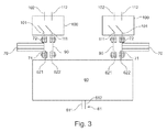
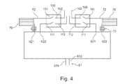
- the output 52 of the inverter 50 is connected directly to an input 61 of a transformer 60 without the interposition of an electrical line.
- the transformer has two outputs 62 on the secondary side. With the transformer 60, on the one hand, the voltage or the current can be transformed. On the other hand, two antiphase alternating voltages with the same effective voltages can be provided at the outputs. This is achieved by oppositely wound secondary windings, which are flooded by the same magnetic flux.
- the outputs 62 each have a first terminal 621 for an outer conductor and a second terminal 622 for a neutral conductor.
- the second terminals 622 are connected to each other inside or outside the transformer 60 (not shown) and form on the secondary side a neutral conductor of a secondary-side two-phase AC system with a phase shift of 180 ° between the phase voltages.
- the first two terminals 621 form outer conductors of the two-phase AC system. No voltage drops between the first two terminals 621, i. the conductor voltage is zero.
- the first terminals 621 of the outputs 62 of the transformer 60 are connected to directly and without the interposition of an electrical line to a first terminal 71 of a capacitor 70.
- Second terminals 72 of the capacitors 70 are connected either with the interposition of an electrical line 80 (FIG. Fig. 2 ) or directly and without the interposition of an electrical line ( Fig. 3 . Fig. 4 ) are each connected to a first contact 101 of one of two first switches 100.
- the first switches 100 each have a second contact 102, which form the first terminals of the two outputs of the arrangement according to the invention.
- the first contact 101 and the second contact 102 of a first switch 100 can be electrically connected by switching.
- the second terminals 622 of the outputs 62 of the transformer 60 are connected either with the interposition of an electrical line 90 (FIG. Fig. 2 . Fig. 3 ) or directly and without the interposition of an electrical line ( Fig. 4 ) are each connected to a first contact 111 of a second switch 110.
- the second switches 110 have second contacts 112, which form a second terminal of an output of the arrangement according to the invention. Also, the first contact 111 and the second contact 112 of a second switch 110 can be electrically connected by switching.
Landscapes
- Engineering & Computer Science (AREA)
- Power Engineering (AREA)
- Physics & Mathematics (AREA)
- Electromagnetism (AREA)
- General Physics & Mathematics (AREA)
- Radar, Positioning & Navigation (AREA)
- Automation & Control Theory (AREA)
- Inverter Devices (AREA)
Priority Applications (6)
| Application Number | Priority Date | Filing Date | Title |
|---|---|---|---|
| EP11168490A EP2530820A1 (fr) | 2011-06-01 | 2011-06-01 | Agencement destiné à orienter du courant et doté d'un onduleur |
| US13/299,414 US20120307525A1 (en) | 2011-06-01 | 2011-11-18 | Arrangement for current conversion with an inverter |
| CN2012101643786A CN102810994A (zh) | 2011-06-01 | 2012-05-24 | 以逆变器进行电流转换的装置 |
| KR1020120056582A KR20120135056A (ko) | 2011-06-01 | 2012-05-29 | 인버터를 구비한 전류변환 장치 |
| RU2012122540/07A RU2012122540A (ru) | 2011-06-01 | 2012-05-31 | Устройство для преобразования тока с инвертором |
| JP2012126532A JP2012254013A (ja) | 2011-06-01 | 2012-06-01 | インバータによる電流変換のためのシステム |
Applications Claiming Priority (1)
| Application Number | Priority Date | Filing Date | Title |
|---|---|---|---|
| EP11168490A EP2530820A1 (fr) | 2011-06-01 | 2011-06-01 | Agencement destiné à orienter du courant et doté d'un onduleur |
Publications (1)
| Publication Number | Publication Date |
|---|---|
| EP2530820A1 true EP2530820A1 (fr) | 2012-12-05 |
Family
ID=44741153
Family Applications (1)
| Application Number | Title | Priority Date | Filing Date |
|---|---|---|---|
| EP11168490A Withdrawn EP2530820A1 (fr) | 2011-06-01 | 2011-06-01 | Agencement destiné à orienter du courant et doté d'un onduleur |
Country Status (6)
| Country | Link |
|---|---|
| US (1) | US20120307525A1 (fr) |
| EP (1) | EP2530820A1 (fr) |
| JP (1) | JP2012254013A (fr) |
| KR (1) | KR20120135056A (fr) |
| CN (1) | CN102810994A (fr) |
| RU (1) | RU2012122540A (fr) |
Citations (4)
| Publication number | Priority date | Publication date | Assignee | Title |
|---|---|---|---|---|
| DE202004014812U1 (de) * | 2004-09-21 | 2004-11-18 | Aeg Svs Power Supply Systems Gmbh | Anordnung zur Versorgung von veränderlichen Lasten |
| US20060152318A1 (en) * | 2005-01-12 | 2006-07-13 | Alexander Isurin | High-frequency power transformer |
| EP2100851A2 (fr) | 2008-03-10 | 2009-09-16 | AEG Power Solutions B.V. | Dispositif et procédé de production d'une répartition régulière de température dans des tiges de silicium lors d'un procédé de séparation |
| EP2346150A1 (fr) * | 2010-01-14 | 2011-07-20 | AEG Power Solutions B.V. | Agencement modulaire d'alimentation en tension, notamment pour réacteurs destinés à la fabrication de poly-silicium |
Family Cites Families (7)
| Publication number | Priority date | Publication date | Assignee | Title |
|---|---|---|---|---|
| GB1114713A (en) * | 1964-12-09 | 1968-05-22 | Atomic Energy Authority Uk | Improvements in or relating to high-voltage pulse-generating transformers and circuits for use therewith |
| US3546565A (en) * | 1968-10-29 | 1970-12-08 | Sangamo Electric Co | Compensation of input direct current component in a current transformer |
| US4602235A (en) * | 1984-08-20 | 1986-07-22 | Micron Industries Corp. | Transformer assembly with terminal plates in support |
| US5811938A (en) * | 1995-06-01 | 1998-09-22 | The Bodine Company, Inc. | Emergency lighting ballast for starting and operating two compact fluorescent lamps with integral starter |
| FR2846485B1 (fr) * | 2002-10-23 | 2005-01-28 | Renault Sa | Dispositif de commande electronique d'un actionneur piezoelectrique ultrasonore |
| CN101559948B (zh) * | 2008-03-10 | 2014-02-26 | 安奕极电源系统有限责任公司 | 在沉积工艺期间在硅棒中产生均匀温度分布的装置和方法 |
| US8169801B2 (en) * | 2009-05-28 | 2012-05-01 | Monolithic Power Systems, Inc. | Voltage converters with integrated low power leaker device and associated methods |
-
2011
- 2011-06-01 EP EP11168490A patent/EP2530820A1/fr not_active Withdrawn
- 2011-11-18 US US13/299,414 patent/US20120307525A1/en not_active Abandoned
-
2012
- 2012-05-24 CN CN2012101643786A patent/CN102810994A/zh active Pending
- 2012-05-29 KR KR1020120056582A patent/KR20120135056A/ko not_active Withdrawn
- 2012-05-31 RU RU2012122540/07A patent/RU2012122540A/ru not_active Application Discontinuation
- 2012-06-01 JP JP2012126532A patent/JP2012254013A/ja active Pending
Patent Citations (4)
| Publication number | Priority date | Publication date | Assignee | Title |
|---|---|---|---|---|
| DE202004014812U1 (de) * | 2004-09-21 | 2004-11-18 | Aeg Svs Power Supply Systems Gmbh | Anordnung zur Versorgung von veränderlichen Lasten |
| US20060152318A1 (en) * | 2005-01-12 | 2006-07-13 | Alexander Isurin | High-frequency power transformer |
| EP2100851A2 (fr) | 2008-03-10 | 2009-09-16 | AEG Power Solutions B.V. | Dispositif et procédé de production d'une répartition régulière de température dans des tiges de silicium lors d'un procédé de séparation |
| EP2346150A1 (fr) * | 2010-01-14 | 2011-07-20 | AEG Power Solutions B.V. | Agencement modulaire d'alimentation en tension, notamment pour réacteurs destinés à la fabrication de poly-silicium |
Non-Patent Citations (2)
| Title |
|---|
| BYUNG-HWAN JEONG ET AL: "A novel pulse power supply for magnetron using high voltage capacitor embedded high frequency transformer", 2004 IEEE APPLIED POWER ELECTRONICS CONFERENCE AND EXPOSITION, APEC 04, IEEE, ANAHEIM, CA, USA, vol. 3, 22 February 2004 (2004-02-22), pages 1819 - 1824, XP010704586, ISBN: 978-0-7803-8269-5, DOI: 10.1109/APEC.2004.1296113 * |
| G. K. DUBEY, S. R. DORADLA, A. JOSHI, R. M. K. SINHA: "Thyristorised Power Controllers" |
Also Published As
| Publication number | Publication date |
|---|---|
| JP2012254013A (ja) | 2012-12-20 |
| CN102810994A (zh) | 2012-12-05 |
| KR20120135056A (ko) | 2012-12-12 |
| US20120307525A1 (en) | 2012-12-06 |
| RU2012122540A (ru) | 2013-12-10 |
Similar Documents
| Publication | Publication Date | Title |
|---|---|---|
| EP3172823B1 (fr) | Convertisseur continu/continu comportant un transformateur | |
| EP2346150A1 (fr) | Agencement modulaire d'alimentation en tension, notamment pour réacteurs destinés à la fabrication de poly-silicium | |
| EP2670041B1 (fr) | Agencement d'alimentation électrique avec un onduleur pour la génération de courant alternatif de phase N | |
| EP2302782A1 (fr) | Agencement de convertisseur de courant | |
| EP3080821A1 (fr) | Dispositif et procédé visant à réduire une composante de flux magnétique continu dans le noyau d'un transformateur | |
| EP2865087B1 (fr) | Onduleurs parallèles avec inductance | |
| EP2670040B1 (fr) | Agencement d'alimentation électrique avec un onduleur pour la génération de courant alternatif monophasé | |
| EP2831894B1 (fr) | Transformateur de réseau local | |
| EP3304718B1 (fr) | Convertisseur continu-continu pour hautes tensions | |
| EP2530820A1 (fr) | Agencement destiné à orienter du courant et doté d'un onduleur | |
| WO2020078967A1 (fr) | Système onduleur avec un module à demi-pont | |
| DE102012216693A1 (de) | 3-Phasen-Drossel mit Gleichtaktunterdrückungsverbindung | |
| EP3218980B1 (fr) | Procédé de transmission à courant continu | |
| EP4464126B1 (fr) | Dispositif de chauffage par induction, système, ligne de production, procédé et utilisation | |
| EP1870996A1 (fr) | Circuit pour alimenter d'énergie electrique dans un reseau de distribution électrique | |
| DE102023118387B3 (de) | Vorrichtung zum erzeugen einer geregelten gleichspannung, vorrichtung zum erzeugen einer geregelten wechselspannung sowie verfahren zur betätigung der beiden vorrichtungen | |
| EP3402062B1 (fr) | Couplage d'au moins deux convertisseurs modulaires à niveaux multiples | |
| WO2016050533A1 (fr) | Convertisseur direct multi-niveaux modulaire à sortie de fréquence variable monophasée | |
| EP3446320B1 (fr) | Bobine d'inductance triphasée | |
| EP3216098B1 (fr) | Circuit de filtrage pour compenser les courants de neutre dans les réseaux électriques | |
| EP4559081A1 (fr) | Dispositif permettant d'alimenter en courant continu des cellules d'électrolyse | |
| AT402463B (de) | Verfahren zum feinstufigen einstellen der leistung eines widerstandes | |
| DE102022211926A1 (de) | Schweißgerät | |
| DE102014226252A1 (de) | Leistungskombinationsvorrichtung zur Anbindung von Windpark-Anlagen an Mittel- und Hochspannungsnetze | |
| DE102020107496A1 (de) | Vorrichtung zum induktiven Erhitzen von Werkstücken und Induktorsystem |
Legal Events
| Date | Code | Title | Description |
|---|---|---|---|
| PUAI | Public reference made under article 153(3) epc to a published international application that has entered the european phase |
Free format text: ORIGINAL CODE: 0009012 |
|
| 17P | Request for examination filed |
Effective date: 20120312 |
|
| AK | Designated contracting states |
Kind code of ref document: A1 Designated state(s): AL AT BE BG CH CY CZ DE DK EE ES FI FR GB GR HR HU IE IS IT LI LT LU LV MC MK MT NL NO PL PT RO RS SE SI SK SM TR |
|
| AX | Request for extension of the european patent |
Extension state: BA ME |
|
| RAP1 | Party data changed (applicant data changed or rights of an application transferred) |
Owner name: AEG POWER SOLUTIONS GMBH |
|
| 17Q | First examination report despatched |
Effective date: 20150313 |
|
| STAA | Information on the status of an ep patent application or granted ep patent |
Free format text: STATUS: THE APPLICATION IS DEEMED TO BE WITHDRAWN |
|
| 18D | Application deemed to be withdrawn |
Effective date: 20150924 |