EP2531059B1 - Verschlussvorrichtung - Google Patents
Verschlussvorrichtung Download PDFInfo
- Publication number
- EP2531059B1 EP2531059B1 EP11709657.8A EP11709657A EP2531059B1 EP 2531059 B1 EP2531059 B1 EP 2531059B1 EP 11709657 A EP11709657 A EP 11709657A EP 2531059 B1 EP2531059 B1 EP 2531059B1
- Authority
- EP
- European Patent Office
- Prior art keywords
- connecting module
- closure device
- opening direction
- closing direction
- connection module
- Prior art date
- Legal status (The legal status is an assumption and is not a legal conclusion. Google has not performed a legal analysis and makes no representation as to the accuracy of the status listed.)
- Active
Links
Images



Classifications
-
- A—HUMAN NECESSITIES
- A45—HAND OR TRAVELLING ARTICLES
- A45C—PURSES; LUGGAGE; HAND CARRIED BAGS
- A45C13/00—Details; Accessories
- A45C13/10—Arrangement of fasteners
-
- A—HUMAN NECESSITIES
- A44—HABERDASHERY; JEWELLERY
- A44D—INDEXING SCHEME RELATING TO BUTTONS, PINS, BUCKLES OR SLIDE FASTENERS, AND TO JEWELLERY, BRACELETS OR OTHER PERSONAL ADORNMENTS
- A44D2200/00—General types of fasteners
- A44D2200/10—Details of construction
- A44D2200/12—Details of construction made of two identical elements
-
- Y—GENERAL TAGGING OF NEW TECHNOLOGICAL DEVELOPMENTS; GENERAL TAGGING OF CROSS-SECTIONAL TECHNOLOGIES SPANNING OVER SEVERAL SECTIONS OF THE IPC; TECHNICAL SUBJECTS COVERED BY FORMER USPC CROSS-REFERENCE ART COLLECTIONS [XRACs] AND DIGESTS
- Y10—TECHNICAL SUBJECTS COVERED BY FORMER USPC
- Y10T—TECHNICAL SUBJECTS COVERED BY FORMER US CLASSIFICATION
- Y10T403/00—Joints and connections
- Y10T403/30—Laterally related members connected by latch means, e.g., scaffold connectors
Definitions
- the invention relates to a closure device for connecting two parts according to the preamble of claim 1.
- Such a closure device has a first connection module and a second connection module, which can be arranged in a closing direction to one another and mechanically locked in a closed position with each other (see WO 2009/103279 ). By moving the first connection module or a part of the first connection module in an opening direction that differs from the closing direction, the first connection module can then be detached from the second connection module, in this way opening the closure device.
- connection modules are attached to each other in a vertical closing direction and thereby lock mechanically.
- first connection module and the second connection module in each case a magnet or on the one hand a magnet and on the other hand a magnetic armature are arranged, the production of the mechanical latching and thus the transfer of the Locking device magnetically supported in the closed position.
- suitable dimensioning of the magnets closing the closure device is largely automatic when the connection modules are approached to each other.
- Locking devices of this type on the one hand in their closed position a safe and reliable connection of two parts with each other available and on the other hand can be closed in a simple manner and opened again in a haptic pleasant way.
- the uses of such closure devices extend to devices of a general type for (releasably) connecting two parts, such as closures of bags, flaps or lids, connection device for straps or lines or other components and the like.
- a closure device as for example from the WO 2008/006357 A2 is known, when the first connection module is in the closed position on the second connection module, the first connection module against the closing direction held on the second connection module by the two connection modules are mechanically locked together by a mechanical latching means.
- This mechanical latching device has an elastically resilient spring locking element on one of the connection modules to which a latching projection on the other of the connection modules can be attached in the closing direction, so that the spring locking element is pushed aside to the closing direction and mechanically with the latching projection in the manner of a clip element Engaged and thereby acting against the closing direction acting mechanical latch is made.
- a secure hold of the two connection modules is provided to each other on this mechanical latching.
- One approach to increase the mechanical strength may be to design the mechanical latching device with a locking projection and a spring locking element stable.
- the present invention has for its object to provide a closure device which is particularly strong against the closing direction, in which the transfer of the connection modules in the closed position but not significantly more difficult.
- a closure device of the type mentioned above has a form-locking element arranged on one of the connection modules, which is formed after the locking of the first connection module with the second connection module by moving the first connection module relative to the second connection module against the opening direction with a recess on the another of the connection modules to engage to hold the first connection module in addition to the mechanical latching device against the closing direction in the closed position on the second connection module.
- the form-locking element is preferably designed to produce a positive engagement against the closing direction between the connection modules by engaging in the recess.
- the protrusion engaging in the recess in the closed position provides, in addition to the latching device, a positive connection between the connection modules which, in the manner of an undercut, holds the first connection module to the second connection module.
- the interlocking element may for example be designed in the manner of a pin, by moving the the first connection module is inserted against the opening direction relative to the second connection module in the recess and thus produces a positive connection against the closing direction.
- connection module must be offset by an offset in the opening direction to the second connection module to then move the first connection module to engage the positive-locking element with the associated recess by the offset against the opening direction.
- connection of the two connection modules is not established by simply attaching the first connection module in the closing direction to the second connection module, but first the first connection module must be attached in the closing direction to the second connection module until the latching device engages latchingly, in order then to shift the final connection module relative to the second connection module by the offset against the opening direction for the final transfer to the closed position.
- the latching device may be formed in a specific embodiment by at least one arranged on one of the connection modules plug-in portion and at least one arranged on the other of the connecting modules spring locking element, wherein the plug portion and the spring locking element each have at least one latching projection for producing a counter to the closing direction acting mechanical latching.
- the plug-in portion may be formed as rigid as possible, while the spring locking element is elastically resilient in a direction transverse to the closing direction, so that for attaching the first connection module to the second connection module, the plug portion can be attached to the spring locking element, while the locking projections run each other and the spring locking element thus pushed aside transversely to the closing direction, until the locking projections of the plug-in section and latching the spring locking element positively engage with each other in engagement.
- each connection module can have a plug-in section and at least one spring locking element. This makes it possible to construct the connection modules of identical construction, wherein the plug-in section of the first connection module with the spring locking element of the second connection module and simultaneously the plug section of the second connection module engage with the spring locking element of the first connection module for closing the closure device.
- each connection module may have a form-locking element and a recess associated with the positive-locking element of the other connection module.
- each connection module has a form-locking element and a recess, wherein after latching by the latching device and moving the connection modules against the opening direction to each other, the projection of the first connection module with the recess of the second connection module and the projection of the second connection module with the recess of first connection module engage.
- a particularly strong, also symmetrical, additional positive connection against the closing direction is provided, which ensures a high mechanical strength of the closure device against large load forces.
- the closure device can be fundamentally designed purely mechanically without magnetic means. Closing then takes place by a manual attachment of the first connection module to the second connection module and a manual engagement of the latching device.
- the closure device can have magnetic means which, in order to support the transfer of the first connection module into the closed position, bring about a magnetic attraction between the first connection module and the second connection module.
- These magnetic means may, for example, be formed by magnets arranged on the connection modules or by a magnet arranged on the one connection module and a magnetic anchor arranged on the other connection module.
- the magnetic means may be designed such that it has such a magnetic attraction between the first connection module and the second Cause connection module that when attaching the first connection module to the second connection module, the mechanical locking over the latching device is largely self-produced so that the first connection module automatically locks when applied to the second connection module in a user-friendly way.
- the magnetic means may be configured to magnetically assist in moving the first connection module relative to the second connection module against the opening direction to engage the interlocking element with the associated recess.
- a magnet may be arranged on the first connection module to form a magnet on the second connection module such that they face each other in the closed position when the latching device is latched and the projection engaging with the recess faces frontally with oppositely polarized magnetic poles.
- the opening direction differs from the closing direction. This is to be understood that the opening direction is directed perpendicular or at an oblique angle to the closing direction, but not parallel to the closing direction and not antiparallel, ie opposite to the closing direction.
- the opening direction may for example be directed perpendicular to the closing direction.
- the opening direction is defined by the latching projections of the latching device, which extend, for example, transversely to the closing direction.
- the opening direction is directed tangentially to these latching projections and defines the direction along which the plug portion of one connection module can be tangentially disengaged from the spring latching elements of the other connection module.
- a main loading direction, along which tensile forces act on the closure device is directed at a first oblique angle to the closing direction and at a second oblique angle to the opening direction.
- the second oblique angle preferably corresponds to an obtuse angle greater than 90 ° and less than 180 °. If the main loading direction is directed at an angle greater than 90 ° to the opening direction, this has the consequence that a vector component of the main loading direction is directed against the opening direction. This in turn has the consequence that opening of the closure device is at least made difficult under load, because this must be done against the loading forces to move the first connection module in the opening direction relative to the second connection module.
- a locking device for securing the engagement of the projection with the recess may be provided.
- the locking device locks the first connection module with respect to the second connection module against displacement in the opening direction as soon as the projection has come into engagement with the recess, thus preventing unintentional release of the closure device by moving the connection modules in the opening direction relative to each other. Only by an actuation of the locking device, the first connection module can then be moved in the opening direction relative to the second connection module and the closure device can be opened with it.
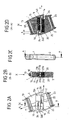
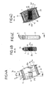
- Fig. 1 to 5 show an embodiment of a closure device with a first connection module 1 and a second connection module 2 in different phases of movement, namely before closing ( Fig. 1A to 1D ), while closing ( Fig. 2A to 2D and Fig. 3A to 3D ), in a closed position ( Figs. 4A to 4D ) and when opening ( Figs. 5A to 5D ).
- FIG. 1A to 1D . 2A to 2D . 3A to 3D . 4A to 4D . 5A to 5D are chosen so that view A is a front view, view B is a sectional view in a sectional plane transverse to the plane of view A, view C is a side view and view D is a sectional view in a sectional plane transverse to the plane of the view C.
- the closure device is formed by a first connection module 1 and a second connection module 2, which can each be connected via a webbing web 13, 23 with a belt or rope.
- the closure device is then used to connect two straps or two other components, which can preferably cause a load in a main loading direction FL on train the closure device.
- Fig. 1A to 1D show the closure device initially in the open state.
- the connection modules 1, 2 are present separately from one another, so that the belts or other components connected to the connection modules 1, 2 are detached from one another.
- connection modules 1, 2 are designed substantially identical.
- the connection modules 1, 2 each have a plug-in section 11, 22 and two spring locking elements 12a, 12b, 21a, 21b, which together form a Forming locking device for mechanical locking of the connection modules with each other.
- the plug-in sections 11, 22 and the spring locking elements 12a, 12b, 21a, 21b in this case each have latching projections 11a, 11b, 120a, 120b, 210a, 210b, 22a, 22b, which are designed to counteract a latching, form-fitting connection a closing direction X between the connection modules 1, 2 produce.
- connection modules 1, 2 can be used to close the closure device, as in Fig. 2A to 2D shown, in the closing direction X are attached to each other.
- the latching projections 22a, 22b of the plug-in section 22 of the second connection module 2 also run onto the latching projections 120a, 120b of the spring latching elements 12a, 12b of the first connection module, so that they too snap into engagement with one another.
- This locked state is in Fig. 3A to 3D shown.
- connection modules 1, 2 are first by an offset A against a perpendicular to the closing direction X directed opening direction Y (see Fig. 2D and 3D ) against each other in their final closed position.
- a respective projection 16, 26 is formed on the front side on the plug-in section 11 of the first connection module 1 and also on the front side on the plug-in section 22 of the second connection module 2, which protrudes axially along the opening direction Y from the respective plug section 11, 22 and a recess 240 or 140 is assigned to the respective other connection module 2 and 1 respectively.
- connection modules 1, 2 serve to provide in a final closed position by engaging in the respective associated recess 240 and 140, an additional positive connection against the closing direction X between the connection modules 1, 2, so that the closure device particularly high loading forces in the Main load direction FL can withstand.
- the connection modules 1, 2 have been attached to each other in the closing direction X and the latching means (formed by the plug sections 11, 22 and the spring locking elements 12a, 12b, 21a, 21b) is locked, the first connection module 1 in addition to the Displacement A against the opening direction Y to move relative to the second connection module 2 in order to bring the closure device in its final closed position, as shown in FIG Figs. 4A to 4D is shown.
- the closure device is then by the mechanical latching of the plug portions 11, 22 with the spring locking elements 12a, 12b, 21a, 21b on the one hand and by the engagement of the projections 16, 26 in the associated recesses 140, 240 safe and mechanically highly resilient against the closing direction X and also against the main load direction FL interconnected.
- Magnetic means 10, 20 are provided on the connection modules 1, 2, which may be formed for example by a respective magnet 10, 20 or on the one hand a magnet and on the other hand a magnetic armature in the form of a core made of a ferromagnetic material. These magnetic means 10, 20 serve to transfer the connection modules 1, 2 in the closed position according to Figs. 4A to 4D to support magnetically and can advantageously be dimensioned so that when attaching the connection modules 1, 2 to each other, the mechanical locking of the plug sections 11, 22 with the spring locking elements 12a, 12b, 21a, 21b can be done in an automatic or at least largely automatic manner and thus a Users the connection modules 1, 2 does not have to laboriously mechanically engage with each other.
- the magnetic means 10, 20 are arranged on the connection modules 1, 2 that they only in the closed position according to Figs. 4A to 4D as far as possible face frontally attractively. If the connection modules 1, 2, as in Fig. 2D and 3D shown, with an offset A in the closing direction X attached to each other, the magnetic means 10, 20, however, offset in the opening direction Y to each other, so that they exert a magnetic attraction against the opening direction Y between the connection modules 1, 2, so that automatically Connecting modules 1, 2 pull against the opening direction Y in the closed position and engage the projections 16, 26 with the associated recesses 240 and 140, respectively.
- the magnetic means 10, 20 may be at least slightly offset in the opening direction Y in the closed position, so that the connecting modules 1, 2 biased in the closed position due to the slight offset of the magnetic means 10, 20 against the opening direction Y to each other and thus the projections 16, 26 are securely pressed into the recesses 240 and 140, respectively.
- the main load direction FL obliquely to the closing direction X and also directed obliquely to the opening direction Y.
- the main load direction FL has here with a direction vector component FLX opposite to the closing direction X and with a direction vector component FLY opposite to the opening direction Y.
- a direction vector component means a vector component of the main load direction FL when projecting onto the closing direction X or the opening direction Y.
- the direction vector component FLX opposite to the closing direction X is the vector component of the main load direction L when projected onto the axis of the closing direction.
- the direction vector component FLY opposite to the opening direction is the projection of the main loading direction FL onto the axis of the opening direction Y.
- the main load direction FL is directed at an obtuse angle (greater than 90 °, but less than 180 °) to the opening direction Y and thus results in a direction vector component FLY of the main load direction FL, which is directed against the opening direction Y, there are several advantageous effects.
- the oblique orientation of the opening direction Y at an obtuse angle to the main loading direction FL causes the closure device to not be opened under load, or at least very difficult to open.
- the projections 16, 26 are also disengaged from the recesses 240 or 140, so that the connection modules 1, 2 can be released from each other when the plug-in sections 11, 22 are disengaged from the spring locking elements 12a, 12b , 21 a, 21 b are as in Figs. 5A to 5D shown.
- the opening can be done in a haptic pleasant way, since the tangential movement of the magnetic means 10, 20 in the opening direction Y can be done without much effort.
- the projections 16, 26 on the plug-in sections 11, 22 are pin-shaped and project axially from the plug-in sections 11, 22.
- the projections 16, 26, which may be formed, for example, as circular cylindrical pins, can hereby be of any desired stability, the stability being essentially dependent on the geometry and the material properties of the projections 16, 26 and the recesses 140 receiving the projections 16, 26 , 240.
- connection modules 1, 2 may be made of metal in this case to ensure a secure, positive engagement.
- Other parts of the connection modules 1, 2 may for example be made of plastic as plastic moldings.
- the magnetic means 10, 20 are not necessarily designed and dimensioned so that they automatically the connection modules 1, 2 against the opening direction Y in the final closed position according to Figs. 4A to 4D pull. It can also be provided that the magnetic means 10, 20 magnetically support only the attachment in the closing direction, the displacement of the connection modules 1, 2 against the opening direction Y to each other, however, must be done manually.
- the displacement movement is supported elastically by the offset A against the opening direction Y by additional mechanical springs.
- a locking device can be provided which locks the first connection module 1 against the second connection module 2 against displacement in the opening direction Y, as soon as the projections 16, 26 with the recesses 140, 240 are engaged.
- a locking device can be provided which locks the first connection module 1 against the second connection module 2 against displacement in the opening direction Y, as soon as the projections 16, 26 with the recesses 140, 240 are engaged.
- the closure device can then be moved into the opening device Y and thus opened only by an additional operation, namely a release of the locking device.
- This locking can for example be realized in that the spring locking elements 12a, 12b, 21a, 21b are still under bias when in the in Fig. 3A to 3D shown state to the male sections 11, 22 have been recognized. You can be designed so that they snap into their final detent position and engage in this example, in associated recesses on the male sections 11, 22, when the final closed position according to Figs. 4A to 4D is reached. To open the closure device then the spring locking elements 12a, 12b, 21a, 21b must be released by active actuation from their engagement in order to move the connection modules 1, 2 in the opening direction Y relative to each other.
- the main loading direction FL does not necessarily have to be directed obliquely to the closing direction X. It is also conceivable that the main load direction antiparallel to the closing direction X, that is directed exactly opposite to the closing direction X.
- closure device can also be designed purely mechanically, without magnetic means being present in the manner described here.
- the idea underlying the invention is not limited to the above-described embodiments, but can be realized in other embodiments of closure devices, as for example from the WO 2008/006357 A2 , of the WO 2009/092368 A2 , of the WO 2010/006594 A2 , of the WO 2008/006354 A2 , of the WO 2008/006356 A2 , of the WO 2009/010049 A2 and the WO 2009/12796 A2 , are known.
- the closing parts are transferred to a closed position in a magnetically assisted manner, so that they are mechanically locked together in a closed position.
- magnetic means are not necessarily provided even in these closure devices.
- the closure devices can also be purely mechanical without magnetic means being present.
- a closure device of the type described is suitable for a variety of different uses and advantageously used.
- the closure device can be used as a closure for bags, rucksacks, suitcases, furniture or other storage or transport or containers.
- the closure device may also be used to releasably connect components or flexible traction means such as ropes or straps (eg for mountaineering equipment or sailing equipment or even dog collars, towing ropes or other ropes or ropes), for attaching motorcycle or bicycle accessories to a motorcycle or bicycle (Such as for attaching saddlebags or other bags or bags, tools or the like) or for baby bowls, strollers or child carrier racks are used.
- the closure device for attaching mobile phones, weapons, truncheons or other utensils can be used on a belt holder.
Landscapes
- Details Of Connecting Devices For Male And Female Coupling (AREA)
- Closures For Containers (AREA)
Description
- Die Erfindung betrifft eine Verschlussvorrichtung zum Verbinden zweier Teile nach dem Oberbegriff des Anspruchs 1.
- Eine derartige Verschlussvorrichtung weist ein erstes Verbindungsmodul und ein zweites Verbindungsmodul auf, die in eine Schließrichtung aneinander anordbar und in einer Schließstellung mechanisch miteinander verrastet sind (siehe
WO 2009/103279 ). Durch eine Bewegung des ersten Verbindungsmoduls oder eines Teils des ersten Verbindungsmoduls in eine Öffnungsrichtung, die sich von der Schließrichtung unterscheidet, kann dann das erste Verbindungsmodul vom zweiten Verbindungsmodul gelöst werden, um auf diese Weise die Verschlussvorrichtung zu öffnen. - Bei einer aus der
WO 2008/006357 A2 bekannten Verschlussvorrichtung dieser Art werden zwei Verbindungsmodule in eine senkrechte Schließrichtung aneinander angesetzt und verrasten dadurch mechanisch. Dadurch, dass sowohl an dem ersten Verbindungsmodul als auch an dem zweiten Verbindungsmodul jeweils ein Magnet oder einerseits ein Magnet und andererseits ein magnetischer Anker angeordnet sind, wird die Herstellung der mechanischen Verrastung und damit die Überführung der Verschlussvorrichtung in die Schließstellung magnetisch unterstützt. Bei geeigneter Dimensionierung der Magnete erfolgt das Schließen der Verschlussvorrichtung weitestgehend selbsttätig, wenn die Verbindungsmodule aneinander angenähert werden. Durch Verschieben oder Verdrehen des ersten Verbindungsmoduls relativ zum zweiten Verbindungsmodul kann die mechanische Verrastung gelöst werden, wobei gleichzeitig die magnetischen Mittel durch seitliche Bewegung voneinander abgeschert und damit voneinander entfernt werden. - Verschlussvorrichtungen dieser Art stellen einerseits in ihrer Schließstellung eine sichere und belastbare Verbindung zweier Teile miteinander zur Verfügung und können andererseits auf einfache Weise geschlossen und auf haptisch angenehme Weise wieder geöffnet werden. Die Einsatzmöglichkeiten derartiger Verschlussvorrichtungen erstrecken sich auf Vorrichtungen allgemeiner Art zum (lösbaren) Verbinden zweier Teile, wie Verschlüsse von Taschen, Klappen oder Deckeln, Verbindungsvorrichtung für Gurte oder Leinen oder andere Bauteile und dergleichen.
- Bei einer Verschlussvorrichtung, wie sie beispielsweise aus der
WO 2008/006357 A2 bekannt ist, wird, wenn sich das erste Verbindungsmodul in der Schließstellung am zweiten Verbindungsmodul befindet, das erste Verbindungsmodul entgegen der Schließrichtung an dem zweiten Verbindungsmodul gehalten, indem die beiden Verbindungsmodule durch eine mechanische Verrastungseinrichtung mechanisch miteinander verrastet sind. Diese mechanische Verrastungseinrichtung weist ein elastisch federndes Federverriegelungselement an einem der Verbindungsmodule auf, an das ein Rastvorsprung an dem anderen der Verbindungsmodule in die Schließrichtung angesetzt werden kann, so dass das Federverriegelungselement quer zur Schließrichtung beiseite gedrängt wird und nach Art eines Clipselements mechanisch mit dem Rastvorsprung in Eingriff gelangt und dadurch eine entgegen der Schließrichtung wirkende mechanische Verrastung hergestellt wird. In der Schließstellung wird über diese mechanische Verrastung ein sicherer Halt der beiden Verbindungsmodule aneinander bereitgestellt. - Es besteht hierbei jedoch ein Bedürfnis für eine weitere Verbesserung einer solchen Verschlussvorrichtung, um die Belastbarkeit einer solchen Verschlussvorrichtung bei einer großen Belastung der Verschlussvorrichtung auf Zug mit entgegen der Schließrichtung wirkenden Belastungskräften zu erhöhen.
- Ein Ansatz, die mechanische Belastbarkeit zu erhöhen, kann darin liegen, die mechanische Verrastungseinrichtung mit einem Rastvorsprung und einem Federverriegelungselement stabiler auszulegen. Dies führt jedoch dazu, dass das Herstellen der Verrastung durch Ansetzen des ersten Verbindungsmoduls in die Schließrichtung an das zweite Verbindungsmodul erschwert wird, weil eine größere Kraft zum Herstellen der Verrastung erforderlich ist. Zudem wird dadurch die Baugröße erhöht, und magnetische Mittel (wenn sie zum Unterstützen der Herstellung der mechanischen Verrastung vorgesehen sein sollen) verteuern sich, weil auch die magnetischen Mittel für eine wirksame Schließunterstützung zum Bereitstellen einer stärkeren magnetischen Anziehungskraft größer zu dimensionieren sind.
- Der vorliegenden Erfindung liegt die Aufgabe zugrunde, eine Verschlussvorrichtung bereitzustellen, die entgegen der Schließrichtung besonders stark belastbar ist, bei der das Überführen der Verbindungsmodule in die Schließstellung aber nicht wesentlich erschwert ist.
- Diese Aufgabe wird durch einen Gegenstand mit den Merkmalen des Anspruchs 1 gelöst.
- Demnach weist eine Verschlussvorrichtung der eingangs genannten Art ein an einem der Verbindungsmodule angeordnetes Formschlusselement auf, das ausgebildet ist, nach Herstellung der Verrastung des ersten Verbindungsmoduls mit dem zweiten Verbindungsmodul durch Bewegen des ersten Verbindungsmoduls relativ zu dem zweiten Verbindungsmodul entgegen der Öffnungsrichtung mit einer Ausnehmung an dem anderen der Verbindungsmodule in Eingriff zu gelangen, um das erste Verbindungsmodul zusätzlich zu der mechanischen Verrastungseinrichtung entgegen der Schließrichtung in der Schließstellung an dem zweiten Verbindungsmodul zu halten.
- Das Formschlusselement ist dabei vorzugsweise ausgebildet, durch Eingreifen in die Ausnehmung einen Formschluss entgegen der Schließrichtung zwischen den Verbindungsmodulen herzustellen.
- Der in der Schließstellung in die Ausnehmung eingreifende Vorsprung stellt, zusätzlich zu der Verrastungseinrichtung, eine formschlüssige Verbindung zwischen den Verbindungsmodulen her, die nach Art einer Hinterschneidung das erste Verbindungsmodul an dem zweiten Verbindungsmodul hält. Das Formschlusselement kann beispielsweise nach Art eines Zapfens ausgebildet sein, der, durch Bewegen des ersten Verbindungsmoduls entgegen der Öffnungsrichtung relativ zu dem zweiten Verbindungsmodul in die Ausnehmung eingeschoben wird und so einen Formschluss entgegen der Schließrichtung herstellt.
- Weil der Vorsprung durch eine Bewegung entgegen der Öffnungsrichtung mit der Ausnehmung in Eingriff gebracht wird, muss weder der Vorsprung noch die den Vorsprung aufnehmende Ausnehmung in Abschnitten elastisch ausgebildet sein. Zum Ineingriffbringen des Vorsprungs mit der Ausnehmung müssen keine Teile elastisch beiseite gedrängt werden. Dies ermöglicht, den Zapfen beliebig stark auszubilden, ohne dass hierdurch das Verrasten und das Überführen in die Schließstellung der beiden Verbindungsmodule wesentlich erschwert wird.
- Vorteilhafterweise muss, zum Schließen der Verschlusseinrichtung, das Verbindungsmodul um einen Versatz in die Öffnungsrichtung versetzt an das zweite Verbindungsmodul angesetzt werden, um das erste Verbindungsmodul dann zum Ineingriffbringen des Formschlusselements mit der zugeordneten Ausnehmung um den Versatz entgegen der Öffnungsrichtung zu bewegen. Mit anderen Worten wird die Verbindung der beiden Verbindungsmodule nicht durch ein einfaches Ansetzen des ersten Verbindungsmoduls in die Schließrichtung an das zweite Verbindungsmodul hergestellt, sondern zunächst muss das erste Verbindungsmodul in die Schließrichtung an das zweite Verbindungsmodul angesetzt werden, bis die Verrastungseinrichtung verrastend in Eingriff gelangt, um dann zum endgültigen Überführen in die Schließstellung das erste Verbindungsmodul um den Versatz entgegen der Öffnungsrichtung relativ zu dem zweiten Verbindungsmodul zu verschieben.
- Die Verrastungseinrichtung kann in einer konkreten Ausgestaltung durch mindestens einen an einem der Verbindungsmodule angeordneten Steckabschnitt und mindestens ein an dem anderen der Verbindungsmodule angeordnetes Federverriegelungselement ausgebildet sein, wobei der Steckabschnitt und das Federverriegelungselement jeweils mindestens einen Rastvorsprung zum Herstellen einer entgegen der Schließrichtung wirkenden mechanischen Verrastung aufweisen. Der Steckabschnitt kann weitestgehend starr ausgebildet sein, während das Federverriegelungselement in eine Richtung quer zur Schließrichtung elastisch federnd ausgebildet ist, so dass zum Ansetzen des ersten Verbindungsmoduls an das zweite Verbindungsmodul der Steckabschnitt an das Federverriegelungselement angesetzt werden kann, dabei die Rastvorsprünge aufeinander auflaufen und das Federverriegelungselement somit quer zur Schließrichtung beiseite gedrängt wird, bis die Rastvorsprünge des Steckabschnitts und des Federverriegelungselements rastend formschlüssig miteinander in Eingriff schnappen.
- In einer vorteilhaften Ausgestaltung kann jedes Verbindungsmodul einen Steckabschnitt und mindestens ein Federverriegelungselement aufweisen. Dies ermöglicht, die Verbindungsmodule baugleich auszubilden, wobei zum Verschließen der Verschlussvorrichtung der Steckabschnitt des ersten Verbindungsmoduls mit dem Federverriegelungselement des zweiten Verbindungsmoduls und gleichzeitig der Steckabschnitt des zweiten Verbindungsmoduls mit dem Federverriegelungselement des ersten Verbindungsmoduls in Eingriff gelangen.
- In diesem Zuge kann auch jedes Verbindungsmodul ein Formschlusselement und eine dem Formschlusselement des anderen Verbindungsmoduls zugeordnete Ausnehmung aufweisen. Mit anderen Worten weist jedes Verbindungsmodul ein Formschlusselement und eine Ausnehmung auf, wobei nach dem Verrasten durch die Verrastungseinrichtung und dem Bewegen der Verbindungsmodule entgegen der Öffnungsrichtung zueinander der Vorsprung des ersten Verbindungsmoduls mit der Ausnehmung des zweiten Verbindungsmoduls und der Vorsprung des zweiten Verbindungsmoduls mit der Ausnehmung des ersten Verbindungsmoduls in Eingriff gelangen. Hierdurch wird eine besonders starke, zudem symmetrische, zusätzliche formschlüssige Verbindung entgegen der Schließrichtung bereitgestellt, die eine hohe mechanische Belastbarkeit der Verschlussvorrichtung auch gegen große Belastungskräfte gewährleistet.
- Die Verschlussvorrichtung kann grundlegend rein mechanisch ohne magnetische Mittel ausgelegt sein. Ein Schließen erfolgt dann durch ein manuelles Ansetzen des ersten Verbindungsmoduls an das zweite Verbindungsmodul und ein manuelles Ineingriffdrücken der Verrastungseinrichtung.
- Die Verschlussvorrichtung kann in einer vorteilhaften Ausgestaltung magnetische Mittel aufweisen, die zur Unterstützung der Überführung des ersten Verbindungsmoduls in die Schließstellung eine magnetische Anziehungskraft zwischen dem ersten Verbindungsmodul und dem zweiten Verbindungsmodul bewirken. Diese magnetischen Mittel können beispielsweise durch an den Verbindungsmodulen angeordnete Magnete oder durch einen an dem einen Verbindungsmodul angeordneten Magneten und einen an dem anderen Verbindungsmodul angeordneten magnetischen Anker ausgebildet sein. Die magnetischen Mittel können dabei so ausgebildet sein, dass sie eine solche magnetische Anziehungskraft zwischen dem ersten Verbindungsmodul und dem zweiten Verbindungsmodul bewirken, dass bei Ansetzen des ersten Verbindungsmoduls an das zweite Verbindungsmodul die mechanische Verrastung über die Verrastungseinrichtung weitestgehend selbsttätig hergestellt wird, so dass das erste Verbindungsmodul bei Ansetzen an das zweite Verbindungsmodul in für einen Nutzer angenehmer Weise selbsttätig verrastet.
- Zusätzlich können die magnetischen Mittel so ausgebildet sein, dass sie das Bewegen des ersten Verbindungsmoduls relativ zu dem zweiten Verbindungsmodul entgegen der Öffnungsrichtung zum in Eingriffbringen des Formschlusselements mit der zugeordneten Ausnehmung magnetisch unterstützen. Hierzu kann beispielsweise ein Magnet an dem ersten Verbindungsmodul so zu einem Magneten an dem zweiten Verbindungsmodul angeordnet sein, dass diese sich in der Schließstellung bei verrasteter Verrastungseinrichtung und mit der Ausnehmung in Eingriff stehendem Vorsprung sich frontal mit entgegengesetzt polarisierten Magnetpolen gegenüberstehen. Wird das erste Verbindungsmodul um den Versatz an dem zweiten Verbindungsmodul angeordnet, so bewirken die magnetischen Mittel bei verrasteter Verrastungseinrichtung eine magnetische Anziehungskraft quer zur Schließrichtung entgegen der Öffnungsrichtung, die das erste Verbindungsmodul entgegen der Öffnungsrichtung zu dem zweiten Verbindungsmodul bewegt und den Vorsprung mit der Ausnehmung in Eingriff bringt.
- Die Öffnungsrichtung unterscheidet sich von der Schließrichtung. Hierunter ist zu verstehen, dass die Öffnungsrichtung senkrecht oder unter einem schrägen Winkel zu der Schließrichtung gerichtet ist, nicht aber parallel zur Schließrichtung und auch nicht antiparallel, also entgegengesetzt zur Schließrichtung.
- Die Öffnungsrichtung kann beispielsweise senkrecht zur Schließrichtung gerichtet sein. Die Öffnungsrichtung ist hierbei definiert durch die Rastvorsprünge der Verrastungseinrichtung, die sich beispielsweise quer zur Schließrichtung erstrecken. Die Öffnungsrichtung ist tangential zu diesen Rastvorsprüngen gerichtet und definiert die Richtung, entlang derer der Steckabschnitt des einen Verbindungsmoduls tangential außer Eingriff mit den Federverriegelungselementen des anderen Verbindungsmoduls geschoben werden kann.
- In einer vorteilhaften Ausgestaltung ist eine Hauptbelastungsrichtung, entlang derer Zugkräfte an der Verschlussvorrichtung angreifen, unter einem ersten schrägen Winkel zu der Schließrichtung und unter einem zweiten schrägen Winkel zu der Öffnungsrichtung gerichtet.
- Der zweite schräge Winkel entspricht dabei bevorzugt einem stumpfen Winkel größer 90° und kleiner 180°. Ist die Hauptbelastungsrichtung unter einem Winkel größer als 90° zu der Öffnungsrichtung gerichtet, so hat dies zur Folge, dass eine Vektorkomponente der Hauptbelastungsrichtung entgegen der Öffnungsrichtung gerichtet ist. Dies wiederum hat zur Folge, dass ein Öffnen der Verschlussvorrichtung unter Belastung zumindest erschwert ist, weil hierzu gegen die Belastungskräfte gearbeitet werden muss, um das erste Verbindungsmodul in die Öffnungsrichtung relativ zu dem zweiten Verbindungsmodul zu bewegen. Zudem hat dies zur Folge, dass eine Belastung der Verschlussvorrichtung bewirkt, dass der Eingriff des Vorsprungs mit der Ausnehmung zum Herstellen der zusätzlichen formschlüssigen Verbindung bei Belastung (wenn er noch nicht vollständig hergestellt war) vollständig hergestellt wird und zudem verstärkt wird, weil durch die Belastung die Verbindungsmodule entgegen der Öffnungsrichtung und damit so zueinander belastet werden, dass der Vorsprung in die Ausnehmung gedrückt wird. Bei Belastung wird damit die Verbindung zwischen den Verbindungsmodulen somit noch verstärkt.
- Zusätzlich kann eine Arretierungseinrichtung zum Sichern des Eingriffs des Vorsprungs mit der Ausnehmung vorgesehen sein. Die Arretierungseinrichtung arretiert das erste Verbindungsmodul gegenüber dem zweiten Verbindungsmodul gegen ein Verschieben in die Öffnungsrichtung, sobald der Vorsprung mit der Ausnehmung in Eingriff gelangt ist, und verhindert auf diese Weise ein unbeabsichtigtes Lösen der Verschlussvorrichtung durch ein Bewegen der Verbindungsmodule in die Öffnungsrichtung zueinander. Erst durch eine Betätigung der Arretierungsvorrichtung kann das erste Verbindungsmodul dann in die Öffnungsrichtung relativ zu dem zweiten Verbindungsmodul verschoben und die Verschlussvorrichtung damit geöffnet werden.
- Der der Erfindung zugrundeliegende Gedanke soll nachfolgend anhand der in den Figuren dargestellten Ausführungsbeispiele näher erläutert werden. Es zeigen:
- Fig. 1A
- eine Vorderansicht einer Verschlussvorrichtung mit einem ersten Verbindungsmodul und einem zweiten Verbindungsmodul in geöffnetem Zustand;
- Fig. 1B
- eine Schnittansicht der Anordnung entlang der Linie B - B gemäß
Fig. 1 A; - Fig. 1C
- eine Seitenansicht der Anordnung gemäß
Fig. 1 A; - Fig. 1D
- eine Schnittansicht der Anordnung entlang der Linie A - A gemäß
Fig. 1C ; - Fig. 2A
- eine Vorderansicht der Verschlussvorrichtung beim Schließen in einem Zustand, bevor eine Verrastungseinrichtung der Verschlussvorrichtung in Eingriff gelangt ist;
- Fig. 2B
- eine Schnittansicht der Anordnung entlang der Linie B - B gemäß
Fig. 2A ; - Fig. 2C
- eine Seitenansicht der Anordnung gemäß
Fig. 2A ; - Fig. 2D
- eine Schnittansicht der Anordnung entlang der Linie A - A gemäß
Fig. 2C ; - Fig. 3A
- eine Vorderansicht der Verschlussvorrichtung bei in eine Schließrichtung aneinander angesetzten Verbindungsmodulen;
- Fig. 3B
- eine Schnittansicht der Anordnung entlang der Linie B - B gemäß
Fig. 3A ; - Fig. 3C
- eine Seitenansicht der Anordnung gemäß
Fig. 3A ; - Fig. 3D
- eine Schnittansicht der Anordnung entlang der Linie A - A gemäß
Fig. 3C ; - Fig. 4A
- eine Vorderansicht der Verschlussvorrichtung in einer Schließstellung;
- Fig. 4B
- eine Schnittansicht der Anordnung entlang der Linie B - B gemäß
Fig. 4A ; - Fig. 4C
- eine Seitenansicht der Anordnung gemäß
Fig. 4A ; - Fig. 4D
- eine Schnittansicht der Anordnung entlang der Linie A - A gemäß
Fig. 4C ; - Fig. 5A
- eine Vorderansicht der Verschlussvorrichtung beim Öffnen;
- Fig. 5B
- eine Schnittansicht der Anordnung entlang der Linie B - B gemäß
Fig. 5A ; - Fig. 5C
- eine Seitenansicht der Anordnung gemäß
Fig. 5A und - Fig. 5D
- eine Schnittansicht der Anordnung entlang der Linie A - A gemäß
Fig. 5C . -
Fig. 1 bis 5 (jeweils mit Ansichten A bis D) zeigen ein Ausführungsbeispiel einer Verschlussvorrichtung mit einem ersten Verbindungsmodul 1 und einem zweiten Verbindungsmodul 2 in unterschiedlichen Bewegungsphasen, nämlich vor dem Schließen (Fig. 1A bis 1D ), beim Schließen (Fig. 2A bis 2D undFig. 3A bis 3D ), in einer Schließstellung (Fig. 4A bis 4D ) und beim Öffnen (Fig. 5A bis 5D ). - Die Ansichten in den
Figuren 1A bis 1D ,2A bis 2D ,3A bis 3D ,4A bis 4D ,5A bis 5D sind dabei so gewählt, dass Ansicht A eine Vorderansicht, Ansicht B eine Schnittansicht in einer Schnittebene quer zur Zeichenebene der Ansicht A, Ansicht C eine Seitenansicht und Ansicht D eine Schnittansicht in einer Schnittebene quer zur Zeichenebene der Ansicht C zeigen. - Die Verschlussvorrichtung ist gebildet durch ein erstes Verbindungsmodul 1 und ein zweites Verbindungsmodul 2, die jeweils über einen Gurtbandsteg 13, 23 mit einem Gurt oder Seil verbunden sein können. Die Verschlussvorrichtung dient dann zum Verbinden zweier Gurte oder zweier anderer Bauteile, die vorzugsweise eine Belastung in eine Hauptbelastungsrichtung FL auf Zug der Verschlussvorrichtung bewirken können.
-
Fig. 1A bis 1D zeigen die Verschlussvorrichtung zunächst in geöffnetem Zustand. In diesem Zustand liegen die Verbindungsmodule 1, 2 getrennt voneinander vor, so dass die mit den Verbindungsmodulen 1, 2 verbundenen Gurte oder anderen Bauteile voneinander gelöst sind. - Die Verbindungsmodule 1, 2 sind im Wesentlichen baugleich ausgebildet. Die Verbindungsmodule 1, 2 weisen jeweils einen Steckabschnitt 11, 22 und zwei Federverriegelungselemente 12a, 12b, 21 a, 21 b auf, die zusammen eine Verrastungseinrichtung zum mechanischen Verrasten der Verbindungsmodule miteinander ausbilden. Die Steckabschnitte 11, 22 und die Federverriegelungselemente 12a, 12b, 21 a, 21 b weisen hierbei jeweils Rastvorsprünge 11 a, 11 b, 120a, 120b, 210a, 210b, 22a, 22b auf, die ausgebildet sind, eine rastende, formschlüssige Verbindung entgegen einer Schließrichtung X zwischen den Verbindungsmodulen 1, 2 herzustellen.
- Die Verbindungsmodule 1, 2 können zum Schließen der Verschlussvorrichtung, wie in
Fig. 2A bis 2D dargestellt, in die Schließrichtung X aneinander angesetzt werden. Durch das Ansetzen der Verbindungsmodule 1, 2 in die Schließrichtung X aneinander wird der Steckabschnitt 11 mit seinen Rastvorsprüngen 11 a, 11 b an die Rastvorsprünge 210a, 210b der zumindest abschnittsweise elastisch federnd ausgebildeten Federverriegelungselemente 21 a, 21 b angesetzt, so dass die Rastvorsprünge 11 a, 11 b, 210a, 210b aufeinander auflaufen, die Federverriegelungselemente 21 a, 21 b quer zur Schließrichtung X beiseite nach außen gedrängt werden und der Steckabschnitt 11 mit seinen Rastvorsprüngen 11a, 11b mit den Federverriegelungselementen 21 a, 21 b mit den daran angeordneten Rastvorsprüngen 210a, 210b rastend in Eingriff schnappt. Gleichzeitig laufen auch die Rastvorsprünge 22a, 22b des Steckabschnitts 22 des zweiten Verbindungsmoduls 2 auf die Rastvorsprünge 120a, 120b der Federverriegelungselemente 12a, 12b des ersten Verbindungsmoduls auf, so dass auch diese rastend miteinander in Eingriff schnappen. Dieser verrastete Zustand ist inFig. 3A bis 3D dargestellt. - Wie sich aus
Fig. 2A bis 2D undFig. 3A bis 3D ergibt, sind die Verbindungsmodule 1, 2 zunächst um einen Versatz A entgegen einer senkrecht zur Schließrichtung X gerichteten Öffnungsrichtung Y (sieheFig. 2D und3D ) gegenüber ihrer endgültigen Schließstellung aneinander anzusetzen. Dies ist dadurch bedingt, dass stirnseitig an dem Steckabschnitt 11 des ersten Verbindungsmoduls 1 und auch stirnseitig an dem Steckabschnitt 22 des zweiten Verbindungsmoduls 2 jeweils ein Vorsprung 16, 26 ausgebildet ist, der entlang der Öffnungsrichtung Y von dem jeweiligen Steckabschnitt 11, 22 axial vorsteht und einer Ausnehmung 240 bzw. 140 an dem jeweils anderen Verbindungsmodul 2 bzw. 1 zugeordnet ist. - Diese Vorsprünge 16, 26 dienen dazu, um in einer endgültigen Schließstellung durch einen Eingriff in die jeweils zugeordnete Ausnehmung 240 bzw. 140 eine zusätzliche formschlüssige Verbindung entgegen der Schließrichtung X zwischen den Verbindungsmodulen 1, 2 bereitzustellen, so dass die Verschlussvorrichtung besonders hohen Belastungskräften in die Hauptbelastungsrichtung FL standhalten kann. Nachdem, wie in
Fig. 3A bis 3D dargestellt, die Verbindungsmodule 1, 2 in die Schließrichtung X aneinander angesetzt worden sind und die Verrastungseinrichtung (gebildet durch die Steckabschnitte 11, 22 und die Federverriegelungselemente 12a, 12b, 21 a, 21 b) verrastet ist, ist das erste Verbindungsmodul 1 zusätzlich um den Versatz A entgegen der Öffnungsrichtung Y relativ zu dem zweiten Verbindungsmodul 2 zu bewegen, um die Verschlussvorrichtung in ihre endgültige Schließstellung zu überführen, wie sie inFig. 4A bis 4D dargestellt ist. - In der Schließstellung gemäß
Fig. 4A bis 4D ist die Verschlussvorrichtung dann durch die mechanische Verrastung der Steckabschnitte 11, 22 mit den Federverriegelungselementen 12a, 12b, 21 a, 21 b einerseits und durch den Eingriff der Vorsprünge 16, 26 in die zugeordneten Ausnehmungen 140, 240 sicher und mechanisch hoch belastbar entgegen der Schließrichtung X und auch entgegen der Hauptbelastungsrichtung FL miteinander verbunden. - An den Verbindungsmodulen 1, 2 sind magnetische Mittel 10, 20 vorgesehen, die beispielsweise durch jeweils einen Magneten 10, 20 oder einerseits einen Magneten und andererseits einen magnetischen Anker in Form eines aus einem ferromagnetischen Material hergestellten Kerns ausgebildet sein können. Diese magnetischen Mittel 10, 20 dienen dazu, das Überführen der Verbindungsmodule 1, 2 in die Schließstellung gemäß
Fig. 4A bis 4D magnetisch zu unterstützen und können vorteilhafterweise so dimensioniert sein, dass bei Ansetzen der Verbindungsmodule 1, 2 aneinander die mechanische Verrastung der Steckabschnitte 11, 22 mit den Federverriegelungselementen 12a, 12b, 21a, 21 b in selbsttätiger oder zumindest weitestgehend selbsttätiger Weise erfolgen kann und somit ein Nutzer die Verbindungsmodule 1, 2 nicht aufwändig mechanisch miteinander in Eingriff drücken muss. - Die magnetischen Mittel 10, 20 sind so an den Verbindungsmodulen 1, 2 angeordnet, dass sie erst in der Schließstellung gemäß
Fig. 4A bis 4D weitestgehend frontal sich anziehend gegenüberstehen. Werden die Verbindungsmodule 1, 2, wie inFig. 2D und3D dargestellt, unter einem Versatz A in die Schließrichtung X aneinander angesetzt, so sind die magnetischen Mittel 10, 20 hingegen in die Öffnungsrichtung Y zueinander versetzt, so dass sie eine magnetische Anziehungskraft entgegen der Öffnungsrichtung Y zwischen den Verbindungsmodulen 1, 2 ausüben, damit selbsttätig die Verbindungsmodule 1, 2 entgegen der Öffnungsrichtung Y in die Schließstellung ziehen und die Vorsprünge 16, 26 mit den zugeordneten Ausnehmungen 240 bzw. 140 in Eingriff bringen. - Wie in
Fig. 4D dargestellt, können die magnetischen Mittel 10, 20 auch in der Schließstellung zumindest geringfügig in die Öffnungsrichtung Y zueinander versetzt sein, so dass die Verbindungsmodule 1, 2 auch in der Schließstellung aufgrund des leichten Versatzes der magnetischen Mittel 10, 20 entgegen der Öffnungsrichtung Y zueinander vorgespannt sind und somit die Vorsprünge 16, 26 sicher in die Ausnehmungen 240 bzw. 140 gedrückt werden. - Wie in
Fig. 4A dargestellt, ist die Hauptbelastungsrichtung FL schräg zur Schließrichtung X und auch schräg zur Öffnungsrichtung Y gerichtet. Die Hauptbelastungsrichtung FL weist dabei mit einer Richtungsvektorkomponente FLX entgegen der Schließrichtung X und mit einer Richtungsvektorkomponente FLY entgegen der Öffnungsrichtung Y. - Unter einer Richtungsvektorkomponente ist in diesem Zusammenhang eine Vektorkomponente der Hauptbelastungsrichtung FL bei Projektion auf die Schließrichtung X bzw. die Öffnungsrichtung Y zu verstehen. Die Richtungsvektorkomponente FLX entgegen der Schließrichtung X ist die Vektorkomponente der Hauptbelastungsrichtung L bei Projektion auf die Achse der Schließrichtung. Die Richtungsvektorkomponente FLY entgegen der Öffnungsrichtung ist die Projektion der Hauptbelastungsrichtung FL auf die Achse der Öffnungsrichtung Y.
- Dadurch, dass die Hauptbelastungsrichtung FL unter einem stumpfen Winkel (größer als 90°, aber kleiner als 180°) zur Öffnungsrichtung Y gerichtet ist und sich damit eine Richtungsvektorkomponente FLY der Hauptbelastungsrichtung FL ergibt, die entgegen der Öffnungsrichtung Y gerichtet ist, ergeben sich mehrere vorteilhafte Effekte.
- Zum einen wird bei Belastung der Verschlussvorrichtung in die Hauptbelastungsrichtung FL auf Zug der Eingriff der Vorsprünge 16, 26 mit den Ausnehmungen 240 bzw. 140 verstärkt, da aufgrund einer Belastung in die Hauptbelastungsrichtung FL die Verbindungsmodule 1, 2 entgegen der Öffnungsrichtung Y (über die Richtungsvektorkomponente FLY) belastet werden.
- Zum zweiten wird bei Belastung auch die Überführung der Verschlussvorrichtung in die endgültige Schließstellung unterstützt, indem die Verbindungsmodule 1, 2 entgegen der Öffnungsrichtung Y aufeinander zu bewegt werden, wenn die Verschlussvorrichtung von dem Zustand gemäß
Fig. 3A bis 3D noch nicht oder noch nicht vollständig in die endgültige Schließstellung gemäßFig. 4A bis 4D überführt worden ist. - Zum dritten bewirkt die schräge Ausrichtung der Öffnungsrichtung Y unter einem stumpfen Winkel zu der Hauptbelastungsrichtung FL, dass die Verschlussvorrichtung unter Last nicht oder zumindest nur sehr schwer geöffnet werden kann.
- Denn zum Öffnen muss das erste Verbindungsmodul 1, wie in
Fig. 5A bis 5D dargestellt, in die Öffnungsrichtung Y relativ zu dem zweiten Verbindungsmodul 2 bewegt werden, um die Steckabschnitte 11, 22 mit ihren daran angeordneten Rastvorsprüngen 11 a, 11 b, 22a, 22b tangential in die Öffnungsrichtung Y außer Eingriff mit den Rastvorsprüngen 120a, 120b, 210a, 210b der Federverriegelungselemente 12a, 12b, 21 a, 21 b zu schieben. Durch diese Bewegung in die Öffnungsrichtung Y gelangen auch die Vorsprünge 16, 26 außer Eingriff mit den Ausnehmungen 240 bzw. 140, so dass die Verbindungsmodule 1, 2 voneinander gelöst werden können, wenn die Steckabschnitte 11, 22 außer Eingriff mit den Federverriegelungselementen 12a, 12b, 21 a, 21 b sind, wie inFig. 5A bis 5D dargestellt. - Liegt keine Last in die Hauptbelastungsrichtung FL an der Verschlussvorrichtung an, kann das Öffnen auf haptisch angenehme Weise erfolgen, da die tangentiale Bewegung der magnetischen Mittel 10, 20 in die Öffnungsrichtung Y ohne großen Kraftaufwand erfolgen kann.
- Die Vorsprünge 16, 26 an den Steckabschnitten 11, 22 sind zapfenartig ausgebildet und stehen axial von den Steckabschnitten 11, 22 vor. Die Vorsprünge 16, 26, die beispielsweise wie kreiszylindrische Zapfen geformt sein können, können hierbei beliebig stabil ausgebildet sein, wobei die Stabilität im Wesentlichen abhängig ist von der Geometrie und den Materialeigenschaften der Vorsprünge 16, 26 und der die Vorsprünge 16, 26 aufnehmenden Ausnehmungen 140, 240.
- Die Vorsprünge 16, 26 und eine von einem Grundkörper 15, 25 eines jeden Verbindungsmoduls 1, 2 vorspringende, die Ausnehmung 140, 240 ausbildende Gehäuselasche 14, 24 können hierbei aus Metall gefertigt sein, um einen sicheren, formschlüssigen Eingriff zu gewährleisten. Andere Teile der Verbindungsmodule 1, 2 können beispielsweise aus Kunststoff als Kunststoffformteile hergestellt sein.
- Die magnetischen Mittel 10, 20 sind nicht notwendigerweise so ausgebildet und so dimensioniert, dass sie die Verbindungsmodule 1, 2 selbsttätig entgegen der Öffnungsrichtung Y in die endgültige Schließstellung gemäß
Fig. 4A bis 4D ziehen. Es kann auch vorgesehen sein, dass die magnetischen Mittel 10, 20 lediglich das Ansetzen in die Schließrichtung magnetisch unterstützen, das Verschieben der Verbindungsmodule 1, 2 entgegen der Öffnungsrichtung Y zueinander hingegen manuell erfolgen muss. - Alternativ oder zusätzlich kann auch vorgesehen sein, dass die Verschiebungsbewegung um den Versatz A entgegen der Öffnungsrichtung Y durch zusätzliche mechanische Federn federelastisch unterstützt wird.
- Um den Eingriff der Vorsprünge 16, 26 in den Ausnehmungen 140, 240 zusätzlich zu sichern, kann eine Arretierungseinrichtung vorgesehen sein, die das erste Verbindungsmodul 1 gegenüber dem zweiten Verbindungsmodul 2 gegen ein Verschieben in die Öffnungsrichtung Y arretiert, sobald die Vorsprünge 16, 26 mit den Ausnehmungen 140, 240 in Eingriff gelangt sind. Damit ist eine zusätzliche Sicherung verwirklicht, die ein unbeabsichtigtes Öffnen der Verschlussvorrichtung durch Verschieben der Verbindungsmodule 1, 2 in die Öffnungsrichtung Y zueinander verhindert. Die Verschlussvorrichtung kann dann nur durch eine zusätzliche Bedienung, nämlich ein Lösen der Arretierungseinrichtung, in die Öffnungseinrichtung Y verschoben und damit geöffnet werden.
- Diese Arretierung kann beispielsweise dadurch verwirklicht sein, dass die Federverriegelungselemente 12a, 12b, 21 a, 21 b noch unter Vorspannung stehen, wenn sie in dem in
Fig. 3A bis 3D dargestellten Zustand an die Steckabschnitte 11, 22 angesetzt worden sind. Sie können dabei so ausgestaltet sein, dass sie erst in ihre endgültige Raststellung schnappen und in dieser beispielsweise in zugeordnete Aussparungen an den Steckabschnitten 11, 22 eingreifen, wenn die endgültige Schließstellung gemäßFig. 4A bis 4D erreicht ist. Zum Öffnen der Verschlussvorrichtung müssen dann die Federverriegelungselemente 12a, 12b, 21 a, 21 b durch aktive Betätigung aus ihrem Eingriff gelöst werden, um die Verbindungsmodule 1, 2 in die Öffnungsrichtung Y relativ zueinander bewegen zu können. - Die Hauptbelastungsrichtung FL muss nicht notwendigerweise schräg zur Schließrichtung X gerichtet sein. Denkbar ist auch, dass die Hauptbelastungsrichtung antiparallel zur Schließrichtung X, also genau entgegengesetzt zur Schließrichtung X gerichtet ist.
- Zudem sind nicht notwendigerweise magnetische Mittel vorzusehen. Die Verschlussvorrichtung kann auch rein mechanisch ausgestaltet sein, ohne dass magnetische Mittel nach der hier beschriebenen Art vorhanden sind.
- Der der Erfindung zugrunde liegende Gedanke ist nicht auf die vorangehend geschilderten Ausführungsbeispiele beschränkt, sondern lässt sich auch bei anderen Ausführungsformen von Verschlussvorrichtungen verwirklichen, wie sie beispielsweise aus der
WO 2008/006357 A2 , derWO 2009/092368 A2 , derWO 2010/006594 A2 , derWO 2008/006354 A2 , derWO 2008/006356 A2 , derWO 2009/010049 A2 und derWO 2009/12796 A2 - Bei den hieraus bekannten Verschlussvorrichtungen erfolgt das Überführen der Verschlussteile in eine Schließstellung in magnetisch unterstützter Weise, so dass diese in einer Schließstellung mechanisch miteinander verrastet sind. Magnetische Mittel sind aber auch bei diesen Verschlussvorrichtungen nicht notwendigerweise vorzusehen. Die Verschlussvorrichtungen können auch rein mechanisch ausgestaltet sein, ohne dass magnetische Mittel vorhanden sind.
- Eine Verschlussvorrichtung der geschilderten Art ist für eine Vielzahl von unterschiedlichen Verwendungen geeignet und vorteilhaft einsetzbar. So kann die Verschlussvorrichtung als Verschluss für Taschen, Rucksäcke, Koffer, Möbel oder andere Aufbewahrungs- oder Transportmittel oder Behältnisse eingesetzt werden. Die Versschlussvorrichtung kann zudem zur lösbaren Verbindung von Bauteilen oder flexiblen Zugmitteln wie Seilen oder Bändern (z.B. für die Bergsteigerausrüstung oder Segelausrüstung oder auch für Hundehalsbänder, Abschleppseile oder andere Seile oder Taue), zum Befestigen von Motorrad- oder Fahrradzubehör an einem Motorrad bzw. einem Fahrrad (wie z.B. zum Befestigen von Satteltaschen oder anderen Taschen oder Beuteln, von Werkzeug oder dergleichen) oder für Babyschalen, Kinderwagen oder Kindertragegestelle eingesetzt werden. Zudem kann die Verschlussvorrichtung zum Befestigen von Mobiltelefonen, Waffen, Schlagstöcken oder anderen Utensilien (z.B. für die Polizei) an einer Gürtelhalterung eingesetzt werden.
- Diese Auflistung ist hierbei in keinster Weise beschränkend. Grundsätzlich ist ein Einsatz einer Verschlussvorrichtung der geschilderten Art überall dort möglich und vorteilhaft, wo ein leicht schließender, gleichzeitig im geschlossenen Zustand aber sicher verschlossener und belastbarer Verschluss gewünscht ist.
-
- 1
- Verbindungsmodul
- 10
- Magnet
- 11
- Steckabschnitt
- 11a, 11b
- Rastvorsprung
- 12
- Aufnahmeöffnung
- 12a, 12b
- Federverriegelungselement
- 120a, 120b
- Rastvorsprung
- 13
- Gurtbandsteg
- 14
- Gehäuselasche
- 140
- Ausnehmung
- 15
- Grundkörper
- 16
- Formschlusselement
- 2
- Verbindungsmodul
- 20
- Magnet
- 21
- Aufnahmeöffnung
- 21a, 21b
- Federverriegelungselement
- 210a, 210b
- Rastvorsprung
- 22
- Steckabschnitt
- 22a, 22b
- Rastvorsprung
- 23
- Gurtbandsteg
- 24
- Gehäuselasche
- 240
- Ausnehmung
- 25
- Grundkörper
- 26
- Formschlusselement
- α, β
- Winkel
- A
- Versatz
- FL
- Hauptbelastungsrichtung
- FLY, FLX
- Vektorkomponente
- X
- Schließrichtung
- Y
- Öffnungsrichtung
Claims (13)
- Verschlussvorrichtung zum Verbinden zweier Teile, mit einem ersten Verbindungsmodul (1) und einem zweiten Verbindungsmodul (2), wobei- das erste Verbindungsmodul (1) in eine Schließrichtung (X) an dem zweiten Verbindungsmodul (2) anordbar ist und in einer Schließstellung mit dem zweiten Verbindungsmodul (2) durch eine Verrastungseinrichtung (11, 12a, 12b, 21a, 21b, 22) mechanisch verrastet und entgegen der Schließrichtung (X) an dem zweiten Verbindungsmodul (2) gehalten ist, und- das erste Verbindungsmodul (1) durch eine Bewegung des ersten Verbindungsmoduls (1) oder eines Teils des ersten Verbindungsmoduls (2) in eine Öffnungsrichtung (Y), die sich von der Schließrichtung (X) unterscheidet, vom zweiten Verbindungsmodul (2) lösbar ist,
gekennzeichnet durch
ein an einem der Verbindungsmodule (1, 2) angeordnetes Formschlusselement (16, 26), das ausgebildet ist, nach Herstellung der Verrastung des ersten Verbindungsmoduls (1) mit dem zweiten Verbindungsmodul (2) durch Bewegen des ersten Verbindungsmoduls (1) relativ zu dem zweiten Verbindungsmodul (2) entgegen der Öffnungsrichtung (Y) mit einer Ausnehmung (140, 240) an dem anderen der Verbindungsmodule (1, 2) in Eingriff zu gelangen, um das erste Verbindungsmodul (1) zusätzlich zu der mechanischen Verrastungseinrichtung (11, 12a, 12b, 21 a, 21 b, 22) entgegen der Schließrichtung (X) in der Schließstellung an dem zweiten Verbindungsmodul (2) zu halten. - Verschlussvorrichtung nach Anspruch 1, dadurch gekennzeichnet, dass das Formschlusselement (16, 26) durch Eingreifen in die Ausnehmung (140, 240) einen Formschluss entgegen der Schließrichtung (X) herstellt.
- Verschlussvorrichtung nach Anspruch 1 oder 2, dadurch gekennzeichnet, dass das erste Verbindungsmodul (1) um einen Versatz (A) in die Öffnungsrichtung (Y) an das zweite Verbindungsmodul (2) anzusetzen ist und zum Ineingriffbringen des Formschlusselements (16, 26) mit der zugeordneten Ausnehmung (140, 240) um den Versatz (A) entgegen der Öffnungsrichtung (Y) zu bewegen ist.
- Verschlussvorrichtung nach einem der Ansprüche 1 bis 3, dadurch gekennzeichnet, dass die Verrastungseinrichtung (11, 12a, 12b, 21 a, 21 b, 22) durch mindestens einen an einem der Verbindungsmodule (1, 2) angeordneten Steckabschnitt (11, 22) und mindestens ein an dem anderen der Verbindungsmodule (1, 2) angeordnetes Federverriegelungselement (12a, 12b, 21 a, 21 b) ausgebildet ist, die jeweils mindestens einen Rastvorsprung (11 a, 11 b, 120a, 120b, 210a, 210b, 22a, 22b) zum Herstellen einer entgegen der Schließrichtung (X) wirkenden mechanischen Verrastung aufweisen.
- Verschlussvorrichtung nach Anspruch 4, dadurch gekennzeichnet, dass jedes Verbindungsmodul (1, 2) einen Steckabschnitt (11, 22) und mindestens ein Federverriegelungselement (12a, 12b, 21 a, 21 b) aufweist.
- Verschlussvorrichtung nach einem der vorangehenden Ansprüche, dadurch gekennzeichnet, dass jedes Verbindungsmodul (1, 2) ein Formschlusselement (16, 26) und eine dem Formschlusselement (16, 26) des anderen Verbindungsmoduls (1, 2) zugeordnete Ausnehmung (140, 240) aufweist.
- Verschlussvorrichtung nach einem der vorangehenden Ansprüche, gekennzeichnet durch magnetische Mittel (10, 20), die zur Unterstützung der Überführung des ersten Verbindungsmoduls (1) in die Schließstellung eine magnetische Anziehungskraft zwischen dem ersten Verbindungsmodul (1) und dem zweiten Verbindungsmodul (2) bewirken.
- Verschlussvorrichtung nach Anspruch 7, dadurch gekennzeichnet, dass die magnetischen Mittel (10, 20) durch an den Verbindungsmodulen (1) angeordnete Magnete (10, 20) oder durch einen an dem einen Verbindungsmodul (1, 2) angeordneten Magneten (10, 20) und einen an dem anderen Verbindungsmodul (1, 2) angeordneten magnetischen Anker ausgebildet sind.
- Verschlussvorrichtung nach Anspruch 7 oder 8, dadurch gekennzeichnet, dass die magnetischen Mittel (10, 20) ausgebildet sind, das Bewegen des ersten Verbindungsmoduls (1) relativ zu dem zweiten Verbindungsmodul (2) entgegen der Öffnungsrichtung (Y) zum Ineingriffbringen des Formschlusselements (16, 26) mit der zugeordneten Ausnehmung (140, 240) magnetisch zu unterstützen.
- Verschlussvorrichtung nach einem der vorangehenden Ansprüche, dadurch gekennzeichnet, dass die Öffnungsrichtung (Y) senkrecht zu der Schließrichtung (X) gerichtet ist.
- Verschlussvorrichtung nach einem der vorangehenden Ansprüche, dadurch gekennzeichnet, dass die Öffnungsrichtung (Y) tangential zu sich quer zur Schließrichtung (X) erstreckenden Rastvorsprüngen (11a, 11b, 120a, 120b, 210a, 210b, 22a, 22b) der Verrastungseinrichtung (11, 12a, 12b, 21 a, 21 b, 22) gerichtet ist.
- Verschlussvorrichtung nach einem der vorangehenden Ansprüche, dadurch gekennzeichnet, dass eine Hauptbelastungsrichtung (FL), in die das erste Verbindungsmodul (1) gegenüber dem zweiten Verbindungsmodul (2) auf Zug belastet wird, unter einem ersten schrägen Winkel (α) zu der Schließrichtung (X) und unter einem zweiten schrägen Winkel (β) zu der Öffnungsrichtung (Y) gerichtet ist.
- Verschlussvorrichtung nach einem der vorangehenden Ansprüche, gekennzeichnet durch eine Arretierungseinrichtung zum Sichern des Eingriff des Vorsprungs (16, 26) mit der Ausnehmung (140, 240), wobei die Arretierungseinrichtung das erste Verbindungsmodul (1) gegenüber dem zweiten Verbindungsmodul (2) gegen ein Verschieben in die Öffnungsrichtung (Y) arretiert, sobald der Vorsprung (16, 26) mit der Ausnehmung (140, 240) in Eingriff gelangt ist.
Applications Claiming Priority (2)
| Application Number | Priority Date | Filing Date | Title |
|---|---|---|---|
| DE102010006928 | 2010-02-04 | ||
| PCT/EP2011/051474 WO2011095514A1 (de) | 2010-02-04 | 2011-02-02 | Verschlussvorrichtung |
Publications (2)
| Publication Number | Publication Date |
|---|---|
| EP2531059A1 EP2531059A1 (de) | 2012-12-12 |
| EP2531059B1 true EP2531059B1 (de) | 2014-07-09 |
Family
ID=44010030
Family Applications (1)
| Application Number | Title | Priority Date | Filing Date |
|---|---|---|---|
| EP11709657.8A Active EP2531059B1 (de) | 2010-02-04 | 2011-02-02 | Verschlussvorrichtung |
Country Status (4)
| Country | Link |
|---|---|
| US (1) | US9635919B2 (de) |
| EP (1) | EP2531059B1 (de) |
| CN (1) | CN102740724B (de) |
| WO (1) | WO2011095514A1 (de) |
Families Citing this family (21)
| Publication number | Priority date | Publication date | Assignee | Title |
|---|---|---|---|---|
| DE102013213633A1 (de) * | 2013-07-11 | 2015-01-15 | Fidlock Gmbh | Verschlussvorrichtung |
| EP3192388B1 (de) * | 2014-06-19 | 2020-03-18 | Fidlock GmbH | Schliessvorrichtung |
| WO2016186701A1 (en) | 2015-05-15 | 2016-11-24 | Nike Innovate C.V. | Articles of footwear with an alternate fastening system |
| US9750309B2 (en) | 2016-01-08 | 2017-09-05 | Nike, Inc. | Articles of footwear with an alternate fastening system |
| KR101811501B1 (ko) * | 2015-12-22 | 2017-12-20 | 백지숙 | 배낭의 가슴멜방용 버클 |
| AU2017202217B2 (en) | 2016-04-05 | 2022-10-20 | Mrm Hk Limited | Buckle |
| TWI584755B (zh) * | 2016-11-16 | 2017-06-01 | 倍騰國際股份有限公司 | 磁扣 |
| DE102017215763B3 (de) * | 2017-09-07 | 2018-12-06 | Bruker Biospin Ag | Befestigungsvorrichtung für einen NMR-Probenkopf mit Schnellverschluss |
| CA3101673A1 (en) | 2017-12-07 | 2019-06-07 | Wonderland Switzerland Ag | Magnetic buckling assembly comprising a male buckling component and a female buckling component |
| CN209573440U (zh) | 2018-09-20 | 2019-11-05 | 明门(中国)幼童用品有限公司 | 预防意外释锁的扣具 |
| DE102019201737A1 (de) * | 2019-02-11 | 2020-08-13 | Qundis Gmbh | Aufbau und Verfahren für mehrfachen Schnellverschluss und mehrfache Schnellöffnung |
| TWM590381U (zh) * | 2019-04-17 | 2020-02-11 | 瀚光隆企業有限公司 | 扣具 |
| USD1014328S1 (en) * | 2019-05-23 | 2024-02-13 | Duraflex Hong Kong Limited | Sliding buckle |
| CN117016924A (zh) | 2019-07-17 | 2023-11-10 | 明门瑞士股份有限公司 | 扣具 |
| CN112237315B (zh) | 2019-07-17 | 2023-09-29 | 明门瑞士股份有限公司 | 扣具 |
| USD1028790S1 (en) * | 2021-05-20 | 2024-05-28 | Fidlock Gmbh | Snap buckle |
| JP1757444S (ja) * | 2022-11-30 | 2023-11-15 | バックル | |
| US12310427B2 (en) * | 2022-12-16 | 2025-05-27 | Fastech Asia Worldwide, Ltd. | Closure apparatus |
| USD1116783S1 (en) * | 2023-04-14 | 2026-03-10 | Fidlock Gmbh | Coupler |
| US12133578B1 (en) * | 2023-06-16 | 2024-11-05 | Duraflex Hong Kong Limited | Magnetic buckle |
| US20250160447A1 (en) * | 2023-11-22 | 2025-05-22 | Erin Huitema | Clasp |
Family Cites Families (18)
| Publication number | Priority date | Publication date | Assignee | Title |
|---|---|---|---|---|
| US2625227A (en) * | 1948-01-12 | 1953-01-13 | Isidor B Laskowitz | Pitch change means for helicopter rotors |
| US2956324A (en) * | 1957-10-16 | 1960-10-18 | Underwater Sports Inc | Quick-release buckle |
| GB1332853A (en) * | 1971-04-28 | 1973-10-10 | Walker Ltd Thomas | Fastening devices |
| FR2290860A1 (fr) * | 1974-11-15 | 1976-06-11 | Tarwil Rosoflex | Dispositif de fermeture servant a l'agrafage d'un soutien-gorge |
| US5311647A (en) * | 1990-06-12 | 1994-05-17 | Davida Levy | Jewelry closure having both magnetic and mechanical clasps |
| JPH06127U (ja) * | 1992-06-15 | 1994-01-11 | 有限会社古山商事 | ネックレス等の止め具 |
| US5671516A (en) * | 1996-06-28 | 1997-09-30 | Sartori; Robert C. | Easy connect and release seat belt buckle |
| US6804865B2 (en) * | 2002-07-25 | 2004-10-19 | Sama S.P.A. | Magnetic closure with mutual interlocking system for bags, rucksacks, items of clothing |
| US6857169B2 (en) * | 2002-12-10 | 2005-02-22 | Taiwan Industrial Fastener Corporation | Structure of magnetic buckle |
| WO2008006354A2 (de) | 2006-07-12 | 2008-01-17 | Fidlock Gmbh | Magnetverschluss |
| EP2043475B1 (de) | 2006-07-12 | 2020-08-26 | Fidlock GmbH | Magnetsteckschnalle |
| EP2436280B1 (de) | 2006-07-12 | 2017-05-24 | Fidlock GmbH | Mechanisch-magnetische Verbindungskonstruktion |
| EP2166895B8 (de) | 2007-07-17 | 2012-08-15 | Fidlock GmbH | Mechanisch-magnetische verbindungskonstruktion |
| US7999736B2 (en) | 2007-07-24 | 2011-08-16 | Pepperl + Fuchs Gmbh | Slot antenna and method for its operation |
| CN101925313B (zh) | 2008-01-27 | 2012-10-17 | 费得洛克有限公司 | 卡锁磁体锁合件 |
| CN101951801B (zh) | 2008-02-21 | 2012-11-28 | 费得洛克有限公司 | 带有负载保护的机械磁性连接结构 |
| US8001662B1 (en) * | 2008-02-21 | 2011-08-23 | Gary Guber | Clip device |
| DE102008033546A1 (de) | 2008-07-17 | 2010-02-11 | Fidlock Gmbh | Abgeschirmter Magnetsteckverschluß |
-
2011
- 2011-02-02 EP EP11709657.8A patent/EP2531059B1/de active Active
- 2011-02-02 CN CN201180008417.7A patent/CN102740724B/zh active Active
- 2011-02-02 US US13/576,776 patent/US9635919B2/en active Active
- 2011-02-02 WO PCT/EP2011/051474 patent/WO2011095514A1/de not_active Ceased
Also Published As
| Publication number | Publication date |
|---|---|
| US9635919B2 (en) | 2017-05-02 |
| EP2531059A1 (de) | 2012-12-12 |
| CN102740724A (zh) | 2012-10-17 |
| US20130011179A1 (en) | 2013-01-10 |
| WO2011095514A1 (de) | 2011-08-11 |
| CN102740724B (zh) | 2015-04-01 |
Similar Documents
| Publication | Publication Date | Title |
|---|---|---|
| EP2531059A1 (de) | Verschlussvorrichtung | |
| EP2470041B1 (de) | Mechanischer verschluss mit einer verriegelungsvorrichtung | |
| EP2389084B1 (de) | Verschlussvorrichtung zum verbinden zweier teile | |
| EP2475279B1 (de) | Verschlussvorrichtung | |
| EP2475278B1 (de) | Verschlussvorrichtung | |
| EP2166895B1 (de) | Mechanisch-magnetische verbindungskonstruktion | |
| EP2782468B1 (de) | Verschlussvorrichtung | |
| EP2040572B1 (de) | Mechanisch-magnetische verbindungskonstruktion | |
| EP2833754B1 (de) | Verschlussvorrichtung zum lösbaren verbinden zweier teile | |
| EP3852570B1 (de) | Verschlussvorrichtung mit aneinander ansetzbaren verschlussteilen | |
| EP3652399B1 (de) | Verschlussvorrichtung | |
| DE102012222344A1 (de) | Verschlussvorrichtung zum Verbinden zweier Teile | |
| EP4277489B1 (de) | Magnet-mechanische verschlussvorrichtung | |
| WO2015121208A1 (de) | Steckverbinderteil mit einem rastelement | |
| EP4440363A1 (de) | Gurtbandverschluss | |
| DE102019215277A1 (de) | Verschlussvorrichtung mit aneinander ansetzbaren Verschlussteilen | |
| EP3515224B1 (de) | Verschlussvorrichtung zum verbinden zweier teile | |
| DE102021006521A1 (de) | Magnet-mechanische Verschlussvorrichtung | |
| DE102023127479B3 (de) | Verschlussvorrichtung zum Verbinden zweier Gegenstände | |
| DE102021006521B4 (de) | Magnet-mechanische Verschlussvorrichtung | |
| DE102024133261A1 (de) | Sicherheitsverschluss | |
| DE102020207983A1 (de) | Verbindungsvorrichtung zum lösbaren Verbinden zweier Baugruppen |
Legal Events
| Date | Code | Title | Description |
|---|---|---|---|
| PUAI | Public reference made under article 153(3) epc to a published international application that has entered the european phase |
Free format text: ORIGINAL CODE: 0009012 |
|
| 17P | Request for examination filed |
Effective date: 20120806 |
|
| AK | Designated contracting states |
Kind code of ref document: A1 Designated state(s): AL AT BE BG CH CY CZ DE DK EE ES FI FR GB GR HR HU IE IS IT LI LT LU LV MC MK MT NL NO PL PT RO RS SE SI SK SM TR |
|
| DAX | Request for extension of the european patent (deleted) | ||
| GRAP | Despatch of communication of intention to grant a patent |
Free format text: ORIGINAL CODE: EPIDOSNIGR1 |
|
| INTG | Intention to grant announced |
Effective date: 20131217 |
|
| GRAS | Grant fee paid |
Free format text: ORIGINAL CODE: EPIDOSNIGR3 |
|
| GRAA | (expected) grant |
Free format text: ORIGINAL CODE: 0009210 |
|
| AK | Designated contracting states |
Kind code of ref document: B1 Designated state(s): AL AT BE BG CH CY CZ DE DK EE ES FI FR GB GR HR HU IE IS IT LI LT LU LV MC MK MT NL NO PL PT RO RS SE SI SK SM TR |
|
| REG | Reference to a national code |
Ref country code: GB Ref legal event code: FG4D Free format text: NOT ENGLISH |
|
| REG | Reference to a national code |
Ref country code: CH Ref legal event code: EP Ref country code: AT Ref legal event code: REF Ref document number: 676241 Country of ref document: AT Kind code of ref document: T Effective date: 20140715 |
|
| REG | Reference to a national code |
Ref country code: IE Ref legal event code: FG4D Free format text: LANGUAGE OF EP DOCUMENT: GERMAN |
|
| REG | Reference to a national code |
Ref country code: DE Ref legal event code: R096 Ref document number: 502011003678 Country of ref document: DE Effective date: 20140828 |
|
| REG | Reference to a national code |
Ref country code: NL Ref legal event code: VDEP Effective date: 20140709 |
|
| REG | Reference to a national code |
Ref country code: LT Ref legal event code: MG4D |
|
| PG25 | Lapsed in a contracting state [announced via postgrant information from national office to epo] |
Ref country code: PT Free format text: LAPSE BECAUSE OF FAILURE TO SUBMIT A TRANSLATION OF THE DESCRIPTION OR TO PAY THE FEE WITHIN THE PRESCRIBED TIME-LIMIT Effective date: 20141110 Ref country code: FI Free format text: LAPSE BECAUSE OF FAILURE TO SUBMIT A TRANSLATION OF THE DESCRIPTION OR TO PAY THE FEE WITHIN THE PRESCRIBED TIME-LIMIT Effective date: 20140709 Ref country code: SE Free format text: LAPSE BECAUSE OF FAILURE TO SUBMIT A TRANSLATION OF THE DESCRIPTION OR TO PAY THE FEE WITHIN THE PRESCRIBED TIME-LIMIT Effective date: 20140709 Ref country code: GR Free format text: LAPSE BECAUSE OF FAILURE TO SUBMIT A TRANSLATION OF THE DESCRIPTION OR TO PAY THE FEE WITHIN THE PRESCRIBED TIME-LIMIT Effective date: 20141010 Ref country code: NO Free format text: LAPSE BECAUSE OF FAILURE TO SUBMIT A TRANSLATION OF THE DESCRIPTION OR TO PAY THE FEE WITHIN THE PRESCRIBED TIME-LIMIT Effective date: 20141009 Ref country code: ES Free format text: LAPSE BECAUSE OF FAILURE TO SUBMIT A TRANSLATION OF THE DESCRIPTION OR TO PAY THE FEE WITHIN THE PRESCRIBED TIME-LIMIT Effective date: 20140709 Ref country code: BG Free format text: LAPSE BECAUSE OF FAILURE TO SUBMIT A TRANSLATION OF THE DESCRIPTION OR TO PAY THE FEE WITHIN THE PRESCRIBED TIME-LIMIT Effective date: 20141009 Ref country code: LT Free format text: LAPSE BECAUSE OF FAILURE TO SUBMIT A TRANSLATION OF THE DESCRIPTION OR TO PAY THE FEE WITHIN THE PRESCRIBED TIME-LIMIT Effective date: 20140709 |
|
| REG | Reference to a national code |
Ref country code: FR Ref legal event code: PLFP Year of fee payment: 5 |
|
| PG25 | Lapsed in a contracting state [announced via postgrant information from national office to epo] |
Ref country code: HR Free format text: LAPSE BECAUSE OF FAILURE TO SUBMIT A TRANSLATION OF THE DESCRIPTION OR TO PAY THE FEE WITHIN THE PRESCRIBED TIME-LIMIT Effective date: 20140709 Ref country code: NL Free format text: LAPSE BECAUSE OF FAILURE TO SUBMIT A TRANSLATION OF THE DESCRIPTION OR TO PAY THE FEE WITHIN THE PRESCRIBED TIME-LIMIT Effective date: 20140709 Ref country code: PL Free format text: LAPSE BECAUSE OF FAILURE TO SUBMIT A TRANSLATION OF THE DESCRIPTION OR TO PAY THE FEE WITHIN THE PRESCRIBED TIME-LIMIT Effective date: 20140709 Ref country code: IS Free format text: LAPSE BECAUSE OF FAILURE TO SUBMIT A TRANSLATION OF THE DESCRIPTION OR TO PAY THE FEE WITHIN THE PRESCRIBED TIME-LIMIT Effective date: 20141109 Ref country code: RS Free format text: LAPSE BECAUSE OF FAILURE TO SUBMIT A TRANSLATION OF THE DESCRIPTION OR TO PAY THE FEE WITHIN THE PRESCRIBED TIME-LIMIT Effective date: 20140709 Ref country code: CY Free format text: LAPSE BECAUSE OF FAILURE TO SUBMIT A TRANSLATION OF THE DESCRIPTION OR TO PAY THE FEE WITHIN THE PRESCRIBED TIME-LIMIT Effective date: 20140709 Ref country code: LV Free format text: LAPSE BECAUSE OF FAILURE TO SUBMIT A TRANSLATION OF THE DESCRIPTION OR TO PAY THE FEE WITHIN THE PRESCRIBED TIME-LIMIT Effective date: 20140709 |
|
| REG | Reference to a national code |
Ref country code: DE Ref legal event code: R097 Ref document number: 502011003678 Country of ref document: DE |
|
| PG25 | Lapsed in a contracting state [announced via postgrant information from national office to epo] |
Ref country code: RO Free format text: LAPSE BECAUSE OF FAILURE TO SUBMIT A TRANSLATION OF THE DESCRIPTION OR TO PAY THE FEE WITHIN THE PRESCRIBED TIME-LIMIT Effective date: 20140709 Ref country code: SK Free format text: LAPSE BECAUSE OF FAILURE TO SUBMIT A TRANSLATION OF THE DESCRIPTION OR TO PAY THE FEE WITHIN THE PRESCRIBED TIME-LIMIT Effective date: 20140709 Ref country code: CZ Free format text: LAPSE BECAUSE OF FAILURE TO SUBMIT A TRANSLATION OF THE DESCRIPTION OR TO PAY THE FEE WITHIN THE PRESCRIBED TIME-LIMIT Effective date: 20140709 Ref country code: DK Free format text: LAPSE BECAUSE OF FAILURE TO SUBMIT A TRANSLATION OF THE DESCRIPTION OR TO PAY THE FEE WITHIN THE PRESCRIBED TIME-LIMIT Effective date: 20140709 Ref country code: EE Free format text: LAPSE BECAUSE OF FAILURE TO SUBMIT A TRANSLATION OF THE DESCRIPTION OR TO PAY THE FEE WITHIN THE PRESCRIBED TIME-LIMIT Effective date: 20140709 Ref country code: IT Free format text: LAPSE BECAUSE OF FAILURE TO SUBMIT A TRANSLATION OF THE DESCRIPTION OR TO PAY THE FEE WITHIN THE PRESCRIBED TIME-LIMIT Effective date: 20140709 |
|
| PLBE | No opposition filed within time limit |
Free format text: ORIGINAL CODE: 0009261 |
|
| STAA | Information on the status of an ep patent application or granted ep patent |
Free format text: STATUS: NO OPPOSITION FILED WITHIN TIME LIMIT |
|
| 26N | No opposition filed |
Effective date: 20150410 |
|
| PG25 | Lapsed in a contracting state [announced via postgrant information from national office to epo] |
Ref country code: BE Free format text: LAPSE BECAUSE OF NON-PAYMENT OF DUE FEES Effective date: 20150228 |
|
| PG25 | Lapsed in a contracting state [announced via postgrant information from national office to epo] |
Ref country code: LU Free format text: LAPSE BECAUSE OF FAILURE TO SUBMIT A TRANSLATION OF THE DESCRIPTION OR TO PAY THE FEE WITHIN THE PRESCRIBED TIME-LIMIT Effective date: 20150202 |
|
| REG | Reference to a national code |
Ref country code: CH Ref legal event code: PL |
|
| PG25 | Lapsed in a contracting state [announced via postgrant information from national office to epo] |
Ref country code: MC Free format text: LAPSE BECAUSE OF FAILURE TO SUBMIT A TRANSLATION OF THE DESCRIPTION OR TO PAY THE FEE WITHIN THE PRESCRIBED TIME-LIMIT Effective date: 20140709 Ref country code: LI Free format text: LAPSE BECAUSE OF NON-PAYMENT OF DUE FEES Effective date: 20150228 Ref country code: CH Free format text: LAPSE BECAUSE OF NON-PAYMENT OF DUE FEES Effective date: 20150228 |
|
| REG | Reference to a national code |
Ref country code: IE Ref legal event code: MM4A |
|
| PG25 | Lapsed in a contracting state [announced via postgrant information from national office to epo] |
Ref country code: SI Free format text: LAPSE BECAUSE OF FAILURE TO SUBMIT A TRANSLATION OF THE DESCRIPTION OR TO PAY THE FEE WITHIN THE PRESCRIBED TIME-LIMIT Effective date: 20140709 |
|
| PG25 | Lapsed in a contracting state [announced via postgrant information from national office to epo] |
Ref country code: IE Free format text: LAPSE BECAUSE OF NON-PAYMENT OF DUE FEES Effective date: 20150202 |
|
| REG | Reference to a national code |
Ref country code: FR Ref legal event code: PLFP Year of fee payment: 6 |
|
| PG25 | Lapsed in a contracting state [announced via postgrant information from national office to epo] |
Ref country code: MT Free format text: LAPSE BECAUSE OF FAILURE TO SUBMIT A TRANSLATION OF THE DESCRIPTION OR TO PAY THE FEE WITHIN THE PRESCRIBED TIME-LIMIT Effective date: 20140709 |
|
| REG | Reference to a national code |
Ref country code: FR Ref legal event code: PLFP Year of fee payment: 7 |
|
| REG | Reference to a national code |
Ref country code: AT Ref legal event code: MM01 Ref document number: 676241 Country of ref document: AT Kind code of ref document: T Effective date: 20160202 |
|
| PG25 | Lapsed in a contracting state [announced via postgrant information from national office to epo] |
Ref country code: SM Free format text: LAPSE BECAUSE OF FAILURE TO SUBMIT A TRANSLATION OF THE DESCRIPTION OR TO PAY THE FEE WITHIN THE PRESCRIBED TIME-LIMIT Effective date: 20140709 Ref country code: AT Free format text: LAPSE BECAUSE OF NON-PAYMENT OF DUE FEES Effective date: 20160202 Ref country code: HU Free format text: LAPSE BECAUSE OF FAILURE TO SUBMIT A TRANSLATION OF THE DESCRIPTION OR TO PAY THE FEE WITHIN THE PRESCRIBED TIME-LIMIT; INVALID AB INITIO Effective date: 20110202 |
|
| PG25 | Lapsed in a contracting state [announced via postgrant information from national office to epo] |
Ref country code: TR Free format text: LAPSE BECAUSE OF FAILURE TO SUBMIT A TRANSLATION OF THE DESCRIPTION OR TO PAY THE FEE WITHIN THE PRESCRIBED TIME-LIMIT Effective date: 20140709 |
|
| REG | Reference to a national code |
Ref country code: FR Ref legal event code: PLFP Year of fee payment: 8 |
|
| PG25 | Lapsed in a contracting state [announced via postgrant information from national office to epo] |
Ref country code: MK Free format text: LAPSE BECAUSE OF FAILURE TO SUBMIT A TRANSLATION OF THE DESCRIPTION OR TO PAY THE FEE WITHIN THE PRESCRIBED TIME-LIMIT Effective date: 20140709 |
|
| PG25 | Lapsed in a contracting state [announced via postgrant information from national office to epo] |
Ref country code: AL Free format text: LAPSE BECAUSE OF FAILURE TO SUBMIT A TRANSLATION OF THE DESCRIPTION OR TO PAY THE FEE WITHIN THE PRESCRIBED TIME-LIMIT Effective date: 20140709 |
|
| P01 | Opt-out of the competence of the unified patent court (upc) registered |
Effective date: 20230517 |
|
| PGFP | Annual fee paid to national office [announced via postgrant information from national office to epo] |
Ref country code: GB Payment date: 20260219 Year of fee payment: 16 |
|
| PGFP | Annual fee paid to national office [announced via postgrant information from national office to epo] |
Ref country code: DE Payment date: 20260217 Year of fee payment: 16 |
|
| PGFP | Annual fee paid to national office [announced via postgrant information from national office to epo] |
Ref country code: FR Payment date: 20260219 Year of fee payment: 16 |