EP2531248B1 - Atemkreisvorrichtung - Google Patents
Atemkreisvorrichtung Download PDFInfo
- Publication number
- EP2531248B1 EP2531248B1 EP11737410.8A EP11737410A EP2531248B1 EP 2531248 B1 EP2531248 B1 EP 2531248B1 EP 11737410 A EP11737410 A EP 11737410A EP 2531248 B1 EP2531248 B1 EP 2531248B1
- Authority
- EP
- European Patent Office
- Prior art keywords
- face mask
- breathing circuit
- flexible
- gas
- patient
- Prior art date
- Legal status (The legal status is an assumption and is not a legal conclusion. Google has not performed a legal analysis and makes no representation as to the accuracy of the status listed.)
- Not-in-force
Links
- 230000029058 respiratory gaseous exchange Effects 0.000 title claims description 90
- 239000007789 gas Substances 0.000 claims description 120
- GQPLMRYTRLFLPF-UHFFFAOYSA-N Nitrous Oxide Chemical compound [O-][N+]#N GQPLMRYTRLFLPF-UHFFFAOYSA-N 0.000 claims description 61
- 230000008878 coupling Effects 0.000 claims description 28
- 238000010168 coupling process Methods 0.000 claims description 28
- 238000005859 coupling reaction Methods 0.000 claims description 28
- 239000002912 waste gas Substances 0.000 claims description 26
- 239000001272 nitrous oxide Substances 0.000 claims description 23
- QVGXLLKOCUKJST-UHFFFAOYSA-N atomic oxygen Chemical compound [O] QVGXLLKOCUKJST-UHFFFAOYSA-N 0.000 claims description 21
- 239000001301 oxygen Substances 0.000 claims description 20
- 229910052760 oxygen Inorganic materials 0.000 claims description 20
- 210000002445 nipple Anatomy 0.000 claims description 17
- 239000012530 fluid Substances 0.000 claims description 13
- 239000000203 mixture Substances 0.000 claims description 13
- 238000004891 communication Methods 0.000 claims description 8
- 239000000463 material Substances 0.000 claims description 3
- 238000012864 cross contamination Methods 0.000 claims description 2
- 238000002156 mixing Methods 0.000 claims description 2
- 229920000114 Corrugated plastic Polymers 0.000 claims 1
- 229920002457 flexible plastic Polymers 0.000 claims 1
- 206010002091 Anaesthesia Diseases 0.000 description 30
- 230000037005 anaesthesia Effects 0.000 description 30
- 230000000241 respiratory effect Effects 0.000 description 19
- 230000002000 scavenging effect Effects 0.000 description 16
- 238000007789 sealing Methods 0.000 description 12
- 206010039897 Sedation Diseases 0.000 description 8
- 230000036280 sedation Effects 0.000 description 8
- 239000002699 waste material Substances 0.000 description 7
- 238000010276 construction Methods 0.000 description 6
- 230000002093 peripheral effect Effects 0.000 description 5
- 238000001356 surgical procedure Methods 0.000 description 5
- 230000003444 anaesthetic effect Effects 0.000 description 4
- 230000008901 benefit Effects 0.000 description 4
- 230000013011 mating Effects 0.000 description 4
- 238000000034 method Methods 0.000 description 4
- 230000000712 assembly Effects 0.000 description 3
- 238000000429 assembly Methods 0.000 description 3
- 230000000052 comparative effect Effects 0.000 description 3
- 239000006200 vaporizer Substances 0.000 description 3
- 241000239290 Araneae Species 0.000 description 2
- 230000009471 action Effects 0.000 description 2
- 238000011109 contamination Methods 0.000 description 2
- 238000002788 crimping Methods 0.000 description 2
- 238000002695 general anesthesia Methods 0.000 description 2
- 238000012986 modification Methods 0.000 description 2
- 230000004048 modification Effects 0.000 description 2
- 235000020004 porter Nutrition 0.000 description 2
- 230000000153 supplemental effect Effects 0.000 description 2
- 239000006096 absorbing agent Substances 0.000 description 1
- 230000002411 adverse Effects 0.000 description 1
- 239000003570 air Substances 0.000 description 1
- 230000036592 analgesia Effects 0.000 description 1
- 230000000202 analgesic effect Effects 0.000 description 1
- 239000003994 anesthetic gas Substances 0.000 description 1
- 230000000903 blocking effect Effects 0.000 description 1
- 239000003795 chemical substances by application Substances 0.000 description 1
- 230000035606 childbirth Effects 0.000 description 1
- 150000001875 compounds Chemical class 0.000 description 1
- 239000000356 contaminant Substances 0.000 description 1
- DPYMFVXJLLWWEU-UHFFFAOYSA-N desflurane Chemical compound FC(F)OC(F)C(F)(F)F DPYMFVXJLLWWEU-UHFFFAOYSA-N 0.000 description 1
- 229960003537 desflurane Drugs 0.000 description 1
- 238000013461 design Methods 0.000 description 1
- 238000006073 displacement reaction Methods 0.000 description 1
- 230000006872 improvement Effects 0.000 description 1
- 208000014674 injury Diseases 0.000 description 1
- 238000003780 insertion Methods 0.000 description 1
- 230000037431 insertion Effects 0.000 description 1
- 230000003434 inspiratory effect Effects 0.000 description 1
- 231100000567 intoxicating Toxicity 0.000 description 1
- 230000002673 intoxicating effect Effects 0.000 description 1
- 230000001788 irregular Effects 0.000 description 1
- 238000004519 manufacturing process Methods 0.000 description 1
- 239000007769 metal material Substances 0.000 description 1
- 238000012806 monitoring device Methods 0.000 description 1
- 208000010125 myocardial infarction Diseases 0.000 description 1
- 235000013842 nitrous oxide Nutrition 0.000 description 1
- 230000036407 pain Effects 0.000 description 1
- 239000002245 particle Substances 0.000 description 1
- 244000052769 pathogen Species 0.000 description 1
- 230000003389 potentiating effect Effects 0.000 description 1
- 238000003825 pressing Methods 0.000 description 1
- 239000000932 sedative agent Substances 0.000 description 1
- 230000001624 sedative effect Effects 0.000 description 1
- DFEYYRMXOJXZRJ-UHFFFAOYSA-N sevoflurane Chemical compound FCOC(C(F)(F)F)C(F)(F)F DFEYYRMXOJXZRJ-UHFFFAOYSA-N 0.000 description 1
- 229960002078 sevoflurane Drugs 0.000 description 1
- 230000008733 trauma Effects 0.000 description 1
- 230000002485 urinary effect Effects 0.000 description 1
- 238000009423 ventilation Methods 0.000 description 1
Images


Classifications
-
- A—HUMAN NECESSITIES
- A61—MEDICAL OR VETERINARY SCIENCE; HYGIENE
- A61M—DEVICES FOR INTRODUCING MEDIA INTO, OR ONTO, THE BODY; DEVICES FOR TRANSDUCING BODY MEDIA OR FOR TAKING MEDIA FROM THE BODY; DEVICES FOR PRODUCING OR ENDING SLEEP OR STUPOR
- A61M16/00—Devices for influencing the respiratory system of patients by gas treatment, e.g. ventilators; Tracheal tubes
- A61M16/0057—Pumps therefor
- A61M16/0078—Breathing bags
-
- A—HUMAN NECESSITIES
- A61—MEDICAL OR VETERINARY SCIENCE; HYGIENE
- A61M—DEVICES FOR INTRODUCING MEDIA INTO, OR ONTO, THE BODY; DEVICES FOR TRANSDUCING BODY MEDIA OR FOR TAKING MEDIA FROM THE BODY; DEVICES FOR PRODUCING OR ENDING SLEEP OR STUPOR
- A61M16/00—Devices for influencing the respiratory system of patients by gas treatment, e.g. ventilators; Tracheal tubes
- A61M16/08—Bellows; Connecting tubes ; Water traps; Patient circuits
- A61M16/0883—Circuit type
- A61M16/0891—Closed circuit, e.g. for anaesthesia
-
- A—HUMAN NECESSITIES
- A61—MEDICAL OR VETERINARY SCIENCE; HYGIENE
- A61M—DEVICES FOR INTRODUCING MEDIA INTO, OR ONTO, THE BODY; DEVICES FOR TRANSDUCING BODY MEDIA OR FOR TAKING MEDIA FROM THE BODY; DEVICES FOR PRODUCING OR ENDING SLEEP OR STUPOR
- A61M16/00—Devices for influencing the respiratory system of patients by gas treatment, e.g. ventilators; Tracheal tubes
- A61M16/0003—Accessories therefor, e.g. sensors, vibrators, negative pressure
- A61M16/0009—Accessories therefor, e.g. sensors, vibrators, negative pressure with sub-atmospheric pressure, e.g. during expiration
-
- A—HUMAN NECESSITIES
- A61—MEDICAL OR VETERINARY SCIENCE; HYGIENE
- A61M—DEVICES FOR INTRODUCING MEDIA INTO, OR ONTO, THE BODY; DEVICES FOR TRANSDUCING BODY MEDIA OR FOR TAKING MEDIA FROM THE BODY; DEVICES FOR PRODUCING OR ENDING SLEEP OR STUPOR
- A61M16/00—Devices for influencing the respiratory system of patients by gas treatment, e.g. ventilators; Tracheal tubes
- A61M16/0087—Environmental safety or protection means, e.g. preventing explosion
- A61M16/009—Removing used or expired gases or anaesthetic vapours
-
- A—HUMAN NECESSITIES
- A61—MEDICAL OR VETERINARY SCIENCE; HYGIENE
- A61M—DEVICES FOR INTRODUCING MEDIA INTO, OR ONTO, THE BODY; DEVICES FOR TRANSDUCING BODY MEDIA OR FOR TAKING MEDIA FROM THE BODY; DEVICES FOR PRODUCING OR ENDING SLEEP OR STUPOR
- A61M16/00—Devices for influencing the respiratory system of patients by gas treatment, e.g. ventilators; Tracheal tubes
- A61M16/01—Devices for influencing the respiratory system of patients by gas treatment, e.g. ventilators; Tracheal tubes specially adapted for anaesthetising
-
- A—HUMAN NECESSITIES
- A61—MEDICAL OR VETERINARY SCIENCE; HYGIENE
- A61M—DEVICES FOR INTRODUCING MEDIA INTO, OR ONTO, THE BODY; DEVICES FOR TRANSDUCING BODY MEDIA OR FOR TAKING MEDIA FROM THE BODY; DEVICES FOR PRODUCING OR ENDING SLEEP OR STUPOR
- A61M16/00—Devices for influencing the respiratory system of patients by gas treatment, e.g. ventilators; Tracheal tubes
- A61M16/06—Respiratory or anaesthetic masks
- A61M16/0683—Holding devices therefor
-
- A—HUMAN NECESSITIES
- A61—MEDICAL OR VETERINARY SCIENCE; HYGIENE
- A61M—DEVICES FOR INTRODUCING MEDIA INTO, OR ONTO, THE BODY; DEVICES FOR TRANSDUCING BODY MEDIA OR FOR TAKING MEDIA FROM THE BODY; DEVICES FOR PRODUCING OR ENDING SLEEP OR STUPOR
- A61M16/00—Devices for influencing the respiratory system of patients by gas treatment, e.g. ventilators; Tracheal tubes
- A61M16/08—Bellows; Connecting tubes ; Water traps; Patient circuits
- A61M16/0816—Joints or connectors
- A61M16/0833—T- or Y-type connectors, e.g. Y-piece
-
- A—HUMAN NECESSITIES
- A61—MEDICAL OR VETERINARY SCIENCE; HYGIENE
- A61M—DEVICES FOR INTRODUCING MEDIA INTO, OR ONTO, THE BODY; DEVICES FOR TRANSDUCING BODY MEDIA OR FOR TAKING MEDIA FROM THE BODY; DEVICES FOR PRODUCING OR ENDING SLEEP OR STUPOR
- A61M16/00—Devices for influencing the respiratory system of patients by gas treatment, e.g. ventilators; Tracheal tubes
- A61M16/08—Bellows; Connecting tubes ; Water traps; Patient circuits
- A61M16/0816—Joints or connectors
- A61M16/0841—Joints or connectors for sampling
- A61M16/085—Gas sampling
-
- A—HUMAN NECESSITIES
- A61—MEDICAL OR VETERINARY SCIENCE; HYGIENE
- A61M—DEVICES FOR INTRODUCING MEDIA INTO, OR ONTO, THE BODY; DEVICES FOR TRANSDUCING BODY MEDIA OR FOR TAKING MEDIA FROM THE BODY; DEVICES FOR PRODUCING OR ENDING SLEEP OR STUPOR
- A61M16/00—Devices for influencing the respiratory system of patients by gas treatment, e.g. ventilators; Tracheal tubes
- A61M16/08—Bellows; Connecting tubes ; Water traps; Patient circuits
- A61M16/0875—Connecting tubes
-
- A—HUMAN NECESSITIES
- A61—MEDICAL OR VETERINARY SCIENCE; HYGIENE
- A61M—DEVICES FOR INTRODUCING MEDIA INTO, OR ONTO, THE BODY; DEVICES FOR TRANSDUCING BODY MEDIA OR FOR TAKING MEDIA FROM THE BODY; DEVICES FOR PRODUCING OR ENDING SLEEP OR STUPOR
- A61M16/00—Devices for influencing the respiratory system of patients by gas treatment, e.g. ventilators; Tracheal tubes
- A61M16/10—Preparation of respiratory gases or vapours
- A61M16/1005—Preparation of respiratory gases or vapours with O2 features or with parameter measurement
- A61M16/1015—Preparation of respiratory gases or vapours with O2 features or with parameter measurement using a gas flush valve, e.g. oxygen flush valve
-
- A—HUMAN NECESSITIES
- A61—MEDICAL OR VETERINARY SCIENCE; HYGIENE
- A61M—DEVICES FOR INTRODUCING MEDIA INTO, OR ONTO, THE BODY; DEVICES FOR TRANSDUCING BODY MEDIA OR FOR TAKING MEDIA FROM THE BODY; DEVICES FOR PRODUCING OR ENDING SLEEP OR STUPOR
- A61M16/00—Devices for influencing the respiratory system of patients by gas treatment, e.g. ventilators; Tracheal tubes
- A61M16/10—Preparation of respiratory gases or vapours
- A61M16/104—Preparation of respiratory gases or vapours specially adapted for anaesthetics
-
- A—HUMAN NECESSITIES
- A61—MEDICAL OR VETERINARY SCIENCE; HYGIENE
- A61M—DEVICES FOR INTRODUCING MEDIA INTO, OR ONTO, THE BODY; DEVICES FOR TRANSDUCING BODY MEDIA OR FOR TAKING MEDIA FROM THE BODY; DEVICES FOR PRODUCING OR ENDING SLEEP OR STUPOR
- A61M2202/00—Special media to be introduced, removed or treated
- A61M2202/02—Gases
- A61M2202/0208—Oxygen
-
- A—HUMAN NECESSITIES
- A61—MEDICAL OR VETERINARY SCIENCE; HYGIENE
- A61M—DEVICES FOR INTRODUCING MEDIA INTO, OR ONTO, THE BODY; DEVICES FOR TRANSDUCING BODY MEDIA OR FOR TAKING MEDIA FROM THE BODY; DEVICES FOR PRODUCING OR ENDING SLEEP OR STUPOR
- A61M2202/00—Special media to be introduced, removed or treated
- A61M2202/02—Gases
- A61M2202/0266—Nitrogen (N)
- A61M2202/0283—Nitrous oxide (N2O)
-
- A—HUMAN NECESSITIES
- A61—MEDICAL OR VETERINARY SCIENCE; HYGIENE
- A61M—DEVICES FOR INTRODUCING MEDIA INTO, OR ONTO, THE BODY; DEVICES FOR TRANSDUCING BODY MEDIA OR FOR TAKING MEDIA FROM THE BODY; DEVICES FOR PRODUCING OR ENDING SLEEP OR STUPOR
- A61M2230/00—Measuring parameters of the user
- A61M2230/40—Respiratory characteristics
- A61M2230/43—Composition of exhalation
- A61M2230/432—Composition of exhalation partial CO2 pressure (P-CO2)
Definitions
- the present application relates generally to devices for delivering respiratory gas or gases in medical applications, and more particularly, to a new and improved respiratory face mask and breathing circuit assembly that is especially useful in administering gases, such as anesthesia inhalation agents, or oxygen, or air, or mixtures of same, for medical purposes, and as such represents an improvement over the device or devices disclosed in my prior U.S. application Serial No. 12/455,048; filed May 28, 2009 (Serial No. 2009/0235932A1, published September 24, 2009 ).
- gases such as anesthesia inhalation agents, or oxygen, or air, or mixtures of same
- my prior application I fully disclose a disposable anesthesia face mask assembly having a flexible hollow inflatable sealing cushion extending along substantially the entire peripheral edge of the mask shell or body member to prevent anesthesia gas or the like delivered through the gas portal on the mask from escaping and adversely affecting the surgical environment.
- the unique face mask assembly disclosed in my prior application represents a significant advance over the prior art because, inter alia, it is the only respiratory or anesthesia mask now known having a pneumatic sealing cushion that extends over and under the chin portion of the patient's face and surprisingly, as a result of this unique arrangement, requires only a relatively simple single headstrap or band for maintaining the mask in a stable position even during long duration surgical procedures.
- the mask and headstrap assembly of my prior applications are ideally suited for use during so-called "sedation" anesthesia procedures where the patient breathes on its own.
- nitrous oxide N 2 0
- This compound frequently called “laughing gas” or, “happy gas”
- an analgesic or “light sedative” to ease pain associated with trauma, childbirth or heart attacks, for example, or as a carrier for more potent anesthesia gases (e.g. Desflurane, Sevoflurane).
- nitrous oxide is so safe, easy to handle, and readily available relatively inexpensively, it has been used as an anesthetic in dentistry since the 1800s.
- nitrous oxide When used by a dentist, nitrous oxide is typically administered through a demand-valve or continuous inhaler placed over the patient's nose so that the patient's mouth can be worked on while the patient continues to inhale the gas.
- a full face-mask therefore cannot be used in dentistry, and to avoid build-up of exhaled or waste nitrous oxide, which can pose an intoxicating and prolonged-exposure hazard to the clinic staff in the room where the procedure is being conducted, a continuous-flow-fresh-air ventilation system or nitrous-scavenging system must be used.
- the present application discloses a new and improved respiratory face mask and breathing circuit assembly adapted to be used with commercially available nitrous oxide gas handling equipment commonly and heretofore used in "dentistry.”
- the respiratory face mask and breathing circuit assembly of the present invention completely avoids contaminating the surrounding environment with built-up waste N 2 0 gas thereby facilitating safe and effective "combined” use of such equipment for "sedation" purposes in a hospital or other clinical environment.
- US 2008/251082 A1 discloses a breathing circuit including a patient airway maintaining device, a first tube that includes a substantially rigid elbow and connectors and a flexible tubular extension.
- An inflatable bag is coupled to the first tube and has a pressure relief valve that exhausts into the atmosphere.
- a second tube has a first end that terminates in proximity to the patient airway maintaining device and a second opposed end that terminates external to the first tube.
- a third tube connects an external source of oxygen to the second tube.
- WO 97/00092 A1 discloses an apparatus for providing oxygen to a patient and for precluding contamination of an enclosed atmosphere by the patient's expirations of anesthesia gases or pathogens, said system comprising: a face mask having a central opening for sealingly receiving a cover adapter; a cover adapter having a connector for connecting said mask to a ventilator circuit; a ventilator circuit removably and sealingly connected to said connector of said cover adapter, said circuit including a first conduit for delivering oxygen to a patient and a second conduit for receiving the patient's expirations; and an airator having a pneumatic circuit with a first inspiratory branch interconnected between an oxygen source and the first conduit for delivering the oxygen mixture to the patient, and a second expiratory branch interconnected between the second conduit and a vacuum source for transmitting his expirations, including contaminants.
- US 3 556 097 A discloses an anesthesia gas delivery system for providing an anesthetic gas to a patient including a face mask, first and second conduit means, connector means to connect said first and second conduit means to said face mask, said first conduit means receiving fluid exhaled from the patient, first check valve means connected to said first conduit means to prevent a reverse flow of the exhaled fluid in said first conduit means, a breathing bag associated with said first check valve mean, relief valve means in fluid communication with said first check valve means, exhalation check valve means in fluid communication with said relief valve means, absorber means receiving the exhaled fluid, fluid inlet means for adding fluid to the exhaled fluid, anesthetic vaporizer means receiving the exhaled fluid and adapted to provide fluid for inhalation, said anesthetic vaporizer communicating with said second conduit means, and a filter means removing extraneous particles from fluid circulating in the system, wherein the face mask, connector means, first and second conduit means and the filter means are disposable and readily detachable from said first check valve means and said
- US 4 112 940 A discloses a scavenging valve device for anesthesia gas release in pediatric anesthesia apparatus, said scavenging valve device comprising an anesthesia bag; a scavenging valve of generally conical configuration having an axial bore extending therethrough from an open base to an open apex with a plurality of longitudinally extending fins around the bore in the valve, said scavenging valve having a plurality of external fin-like projections at its base,; and a control valve comprising a pair of nipples each of generally conical configuration in base to base relation with an axial bore extending therethrough from one open apex end to the other, the control valve having a radially extending hole formed therethrough at the juncture of the bases of the nipples, said bore tapering down to each of the apices from the bases, means for coupling one of said nipples at said control valve to said anesthesia bag and the other of said nipples within the scavenging
- the present invention is defined by the subject-matter of claim 1.
- a uniquely combined anesthesia face mask and breathing circuit adapted to be sealing coupled to a conventional "dental" nitrous gas set-up having a fresh-gas-supply module and a vacuum or scavenging module.
- the breathing circuit includes at one end thereof a cylindrical hollow plug or nozzle for insertion within the main gas flow passage of the face mask.
- a fresh-gas, flexible supply tube also is joined to the breathing circuit nozzle and is adapted to be coupled at its opposed distal other end to the outlet nozzle on the fresh gas supply module of the "dental" set-up.
- a collapsible, flexible flow-through gas reservoir bag is suitably provided.
- the reservoir bag's distal end is joined to one end of a gas flow compensator which, in tum, suitably is adapted to be coupled at its other opposed end to the vacuum module of the "dental" set-up.
- the face mask and breathing circuit of the present invention permits fresh gas supplied from the "dental" set-up to be sealingly inhaled continuously by a patient being “sedated” and any and all exhaled waste gas whether expelled through the patient's nose or mouth is safely scavenged via the face mask and the breathing circuit by the vacuum module of the "dental” setup thereby avoiding re-breathing of exhaled gas by the patient and any build-up of waste N 2 0 gas in the surrounding environment.
- the fresh gas supply tube and the exhalation limb of the breathing circuit are replaced by a single length of co-axial flexible tubing connected at one end to the breathing circuit nozzle adapted to be inserted into the face mask main port, and at its other opposed end to a branched coupling.
- the branched coupling in tum, includes a first branch for connection to the fresh gas supply nozzle of the "dental" set-up and a second branch for connection to a flexible flow-through reservoir bag.
- a one-way valve is disposed between the second branch output nozzle and the input of the flexible bag.
- the output of the flexible flow-through bag is connected to the vacuum module of the "dental" set-up.
- the second branch of the coupling, the one-way valve, and the flexible flow-through reservoir bag define the exhalation limb of the breathing circuit.
- Fresh gas is drawn through the first branch coupling, the flexible co-axial tubing and flows into the mask to be inhaled by a patient whereas any exhaled or waste gas flows back through the flexible co-axial tubing, the second branch coupling, the one-way valve, the flexible flow-through reservoir bag and ultimately to the vacuum module of the "dental" set up.
- An even further object of the present invention is to provide a new and improved respiratory face mask and breathing circuit assembly which is susceptible of a low cost of manufacture with regard to both materials and labor, and which accordingly is then susceptible of low prices of sale, thereby making such a face mask and breathing circuit assembly economically available to the medical community.
- Even still another object of the present invention is to provide a new and improved respiratory face mask and breathing circuit assembly that may be used on a patient before, during or after surgery in a safe and efficient manner.
- Still yet another object of the present invention is to provide a new and improved respiratory face mask and breathing circuit assembly where the breathing circuit is adapted to be coupled to the fresh gas supply module of a nitrous oxide "dental set" and further includes means for automatically preventing re-breathing of waste gas exhaled into said breathing circuit.
- Yet still yet another object of the present invention is to provide a new and improved respiratory face mask and breathing circuit assembly where the breathing circuit is adapted to be coupled to the fresh gas supply module of a nitrous oxide "dental set" and further includes an exhalation limb for storing waste gas exhaled into the breathing circuit by the patient and for avoiding re-breathing of any of the waste gas by the patient.
- Another object of the present invention is to provide a new. and improved respiratory face mask characterized by at least two primary components, namely a cup-like shell or receptacle member terminating at its peripheral edge in a peripheral flange, and an annular substantially donut-shaped hollow inflatable cushion or sealing member affixed or otherwise permanently attached to the flange along substantially the flange's entire peripheral extent, in combination with a breathing circuit adapted to be coupled between the cup-like shell member and a device for supplying anesthesia gas normally used in dentistry.
- Even still yet another object of the present invention is to provide a disposable anesthesia face mask and breathing circuit assembly ideally suited for use during "sedation" anesthesia procedures where the patient is self-breathing.
- the present invention is a breathing circuit apparatus as defined in claim 1.
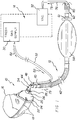
- a comparative example of a respiratory face mask and breathing circuit assembly generally comprising a face mask 10, a breathing circuit 12, and a gas supply and scavenging device 14.
- face mask 10 is fitted on the face of a patient 16 via a headstrap 18 (preferably elastic) removably attachable to the face mask via anchors or the like on the opposed edges thereof.
- the headstrap helps to stabilize the mask on the face and head of a person, preferably before, during and/or after surgery.
- Many of the details of construction of the face mask 10 and headstrap 18 are outside the scope of the present example.
- the interested reader is directed to my prior U.S. application Serial No. 2008/0295845A1, published December 4, 2008 .
- face mask 10 preferably is similar to that fully disclosed in my prior application and therefore, comprises a cup-like shell or receptacle member 20 and a flexible pneumatic (inflatable) cushion member 22.
- the flexible pneumatic inflatable cushion member 22 defines a generally donut-shaped sealing member extending annually along the entire extent of a peripheral rim or flange 24 defined by the shell member 20.
- the crown portion of shell member 20 has a cylindrical hollow inlet member or port 26 suitably sized to removably receive in snug sliding (and sealing) engagement therein the nipple of a conventional breathing circuit and to define a passageway such that anesthesia gas or other gases are adapted to pass from a source through the breathing circuit and the passageway into the interior of shell member 20.
- the breathing circuit also is adapted to receive returned or exhaust gas or gases through the same passageway and convey such exhausted gas or gases to a conventional gas evacuation or scavenging apparatus such as is provided on a standard anesthesia machine used in surgery rooms.
- Shell member 20 also may include a second cylindrical hollow outlet member or port 28 for connection to a length of flexible tube (not shown) the other or distal end of which is adapted suitably to be connected to a conventional CO 2 monitoring device or capnograph for sensing end-tidal CO 2 of a breathing patient.
- the top portion of the mask receives and covers the nose portion of the patient
- the intermediate portion of mask covers the mouth portion of the patient
- the bottom or widest portion of the mask receives and engages the underside of the chin and jaw portion of the patient's face with the pneumatic cushion member 22 effectively serving to seal the periphery of the mask relative to the patient's face and preventing escape of anesthesia gas or other gas into the surrounding environment notwithstanding the irregular contour of the patient's face.
- the foregoing engagement between the underside of the chin or jaw portion of the patient with the bottom or widest transverse edge portion of the mask prevents displacement of the mask toward the ocular area, helps to keep the patient's mouth closed, and securely stabilizes the mask assembly on the face when the elastic headstrap is used thereby freeing both hands of attending anesthesia personnel for use elsewhere.
- the face mask 10, depicted in Figure 1 can be fitted to the face and head of a patient in the foregoing manner, or in the manner described in my prior application.
- a uniquely modified breathing circuit 12 is employed to deliver anesthesia gases or the like originating from gas supply and scavenging device 14 to face mask 10.
- Device 14 is of the well-known type commonly used in the practice of dentistry and comprises inter alia a fresh gas supply module 30 and a vacuum module 32 for scavenging waste gas or exhaled gas.
- a fresh gas supply module 30 and a vacuum module 32 for scavenging waste gas or exhaled gas.
- the gas supply module 30 in such "dental” devices is adapted to supply both nitrous oxide and oxygen and has valve controls for adjusting the flow of each to produce a mixture of any desired concentration.
- Modified breathing circuit 12 includes a Y -connector 34 having a first tubular plug or nipple 36 suitably sized for mating engagement within the first cylindrical inlet member or port 26 on face mask 10.
- Y-connector 34 also features a second tubular branch or nipple 38 for mating with a first open cylindrical end 40 of flexible corrugated tube 42 and a third tubular branch or receptacle 44 for mating with a first tubular end or nipple 46 of elbow connector 48.
- the second or opposed end 50 of elbow connector 48 is adapted to be connected to a flexible "fresh gas" supply tube 52 which in turn is connected to the output of the gas supply module 30 of "dental" gas supply and scavenging device 14 ( Figure 1 ).
- Flexible corrugated tubing 42 terminates in a second open end 54 which in tum is adapted to be matingly engaged with the first cylindrical open end 56 of flexible collapsible reservoir bag 58.
- the opposed second cylindrical end of reservoir bag 58 terminates in a cylindrical plug 60 having a rotatable gate valve therein (not shown) controlled by handle 61. Rotation of handle 61 in either direction about the central longitudinal axis of the plug 60 varies the size of a suitable opening provided in the distal end of plug 60 between a minimum and a maximum extent, respectively.
- the purpose of the gate valve is to adjust the flow of exhaled waste gas through the reservoir bag 58 somewhat if desired as will be made more evident below.
- far breathing circuit 12 is similar to a prior art Modified Jackson Rees (MJR) breathing circuit used in General Anesthesia applications.
- the cylindrical plug 60 located on the second end of reservoir bag 58 is operatively coupled to a gas flow compensator 62 the purpose of which is to automatically assure that any waste gas exhaled into the breathing circuit will not be re-breathed by the patient, or escape into the surrounding environment, but rather will safely be evacuated via the vacuum module 34 of gas supply and scavenging device 14.
- Gas flow compensator 62 generally is tubular in shape and has a first end defining a cylindrical receptacle 64 for receivingly mating with plug 60. The opposed second end of compensator 62 defines a cylindrical opening 66 exposed to the surrounding environment.
- gas flow compensator 62 may advantageously be integrated with plug 60 to form a one-piece or unitary construction.
- the gate valve and its handle 61 is obviated and may be may dispensed with if desired.
- Nozzle 68 Mounted interiorly of compensator 62 substantially medially of the first and second opposed ends thereof and coaxially therewith is a nozzle 68 of reduced diameter relative to both receptacle 64 and opening 66 substantially as shown in Figures 2 and 3 .
- Nozzle 68 preferably is supported at its leftmost end ( Figures 2 and 3 ) by a series of four radial struts 70 which serve as a spider suspending the nozzle in its coaxial orientation, but which allow a quantity of air from the environment to pass through opening 66 from the right to the left, thence through the openings in the spider as indicated by arrows 72, before entering nozzle 68 through the latter's leftmost open side as viewed in Figure 2 .
- a length of flexible tubing 76 is suitably securely affixed to nozzle 68 ( Figure 2 ) proximal to struts 70 and extends coaxially therefrom out through second open end of the compensator 62 ultimately being connected at its other opposed distal end to vacuum module 32 of "dental" device 14.
- the length or axial extent of nozzle 68 is not critical, and it suffices if this part has an axial extent or length sufficient to provide a firm gripping surface for the end of tube 76 attached thereto.
- any exhaled waste gas entering receptacle 64 from reservoir bag 58 (arrows 79, Figure 2 ) as well as a quantity of outside air entering compensator 62 (arrows 72) will be drawn by the vacuum in flexible tube 76 through the left side of nozzle 68 and scavenged by vacuum module 32 of device 14.
- Compensator 62 thus automatically compensates for any dead space in the breathing circuit which might cause exhaled waste gas in the reservoir bag 58 or in the flexible corrugated tubing 42 to stagnate therein and be re-breathed by a patient. Because the face mask 10 has a sealing cushion, leakage of any gas whatsoever into the surrounding environment also is avoided.
- a cylindrical extension sleeve 80 can be attached to the rightmost side of compensator 62 to increase the effective axial extent of the compensator and thereby form a supplemental reservoir for any exhaled waste gas that may travel along a path from bag 58 through plug 60 and pass beyond the leftmost side of nozzle 68. Further tweaking of the flow of gases through the gas flow compensator 62 may optionally be attempted by adjusting the position of the handle 61 of the gate valve on the plug 60, but generally this valve should be placed in the fully "open" position during operation of the disclosed apparatus.
- extension tube 80 and the rightmost end of compensator 62 may be formed of a unitary one-piece construction.
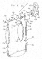
- FIG. 5-8 there is shown a claimed preferred embodiment of the face mask and breathing circuit assembly in accordance with the present invention wherein like reference numerals represent like parts already described.
- face mask 10 is adapted to be coupled or otherwise connected through a suitable breathing circuit 90 to a.
- "dental" set-up supplying a mixture of nitrous oxide and oxygen and having a scavenging or vacuum module.
- the "dental" set-up represented generally by reference sign 100, can be an MXR Flowmeter commercially made available by the aforementioned Porter Instrument, Hatfield, PA 19440.
- this device is mounted on a post supported by a wheeled dolly to render the entire unit portable, or the device may be more permanently mounted on a wall surface via a pivotal bracket or the like.
- the Flowmeter device is located proximal to a supply of fresh inhalation gas or gases such as nitrous oxide and oxygen, for example, and to a source of vacuum, which sources may be made available through a conveniently located wall outlet, and coupled to the Flowmeter device 100 via suitable flexible hoses or tubing, all as is well known in the art of such "dental" devices.
- Flowmeter 100 includes a fresh gas mixing console 102 having valve controls 104, 106 for oxygen (0 2 ) and nitrous oxide (N 2 0), respectively, which when suitably manipulated can produce an output flow of a desired selected mixture of these two gases through an output nozzle 108.
- Flowmeter 100 suitably is adapted to be connected to a source of nitrous oxide and a source of oxygen as schematically indicated by arrows 110 and 112, respectively.
- Nozzle 108 in tum, suitably is connected to an automatic vacuum switch (AVS) module 114 having a fresh (mixed) gas output nozzle 116, a mask-to-vacuum input nipple 118 and vacuum-to-source output nozzle 120.
- AVS automatic vacuum switch
- Nipple 118 is adapted to be connected to the distal end of the exhalation limb of breathing circuit 90 as will be explained in more detail below whereas nozzle 120 is adapted to be connected to a conventional source of "always on" vacuum as schematically indicated by arrow 122 preferably via a suitable flexible hose or tube and vacuum wall outlet (not shown).
- the AVS module 114 includes a safety switch that operates to automatically cut-off the vacuum into the module if the flow of mixed gas (e.g. nitrous/oxygen) through the module is interrupted for any reason during operation of the Flowmeter 100.
- Output nozzle 116 of AVS module 114 suitably is connected to "Bag Tee" coupling 124 which includes an internal passage (not shown) extending between output nozzle 116 and a first output nozzle 126 on the "Bag Tee” coupling.
- First output nozzle 126 in tum, is connected to the cylindrical input collar 130 of closed-end flexible reservoir bag 132.
- the "Bag Tee” coupling 124 further includes a second internal passage (not shown) connected between input collar 130 and a second output nozzle 128 ( Figure 6 ).
- a uni-directional demand valve suitably is included inside of second output nozzle 128 such that any fresh gas (or gas mixture) stored inside flexible reservoir bag 132 is adapted to flow in the direction of arrow 134 when a patient wearing the face mask and breathing circuit of the present invention inhales as will be discussed in greater detail below.
- Flowmeter console 102, switch module 114, Bag Tee coupling 124 and flexible reservoir bag 132 are part and parcel of a conventional "dental" set-up (e.g. MXR Flowmeter) in widespread use for delivering nitrous oxide to a patient in a dentist's chair through a nose mask and therefore the specific details of construction of these components are well known and understood, forming no part of the present invention.
- MXR Flowmeter a conventional "dental" set-up
- patients invariably exhale un-metabolized nitrous oxide into the environment by exhaling through their mouth making the use of such equipment unsuitable in a hospital or clinic environment for "sedation" or other purposes.
- breathing circuit 90 which overcomes the foregoing disadvantage and permits nitrous oxide or other inhalation gases to be employed in a hospital or clinical setting without any contamination of the environment with exhaled gas or gases.
- Breathing circuit 90 includes a first length of flexible tubing 136 adapted to be coupled at a first end thereof to face mask 10.
- the first end of tubing 136 suitably has connected to it a right-angle tube coupling or elbow 138 adapted to be sealingly and securely slidingly fitted into the cylindrical port 26 of the face mask 10.
- the tube coupling elbow 138 has a cylindrical interior through-passage and defines a nipple suitably sized to sealingly and slidingly fit into port 26 of mask 10 for coupling the interior of flexible tubing 136 to the interior of face mask 10.
- the opposite or second end of coaxial-flexible tubing 136 is adapted to be suitably connected to a T-connector 140.
- the first length of flexible tubing 136 preferably is corrugated co-axial tubing which is well known in the art of anesthesia respiratory breathing circuits and which includes an inner corrugated sleeve or tube surrounded by an outer corrugated flexible sleeve or tube, with the inner tube adapted to carry inspired fresh gas and the outer tube adapted to carry exhaled gas to and from a patient usually via a laryngeal entubation device inserted into a patient's throat during surgery.
- co-axial tube 136 includes an outer sleeve 142 and an inner sleeve 144 of reduced diameter relative to outer sleeve 142 suitably supported therein to define a first passage 146 (inhalation) surrounded by a second annular passage 148 (exhalation).
- T-connector 140 preferably is of co-axial design and includes an outer cylindrical wall 150, an inner cylindrical wall 152 of reduced diameter relative to outer cylindrical wall 150, supported therein to define a third passage 154 (inhalation) surrounded by a fourth annular passage 156 (exhalation).
- Inner cylindrical wall 152 protrudes somewhat from outer cylindrical wall 150 to define a reduced-diameter plug 158 adapted to be slidingly and sealingly received in the Tconnector's first end 160 defined by the inner sleeve 144 of co-axial tube when end 162 of outer cylindrical wall is slidingly and sealingly received in end 164 defined by the outer sleeve 142 of co-axial tube 136, all as substantially depicted in Figure 7 .
- inner cylindrical wall 152 of T-connector 140 opens into an enlarged-diameter receptacle 166 at its opposed second end 168 relative to plug 158, which receptacle 166 is in axial open communication with third passage 154.
- T-connector 140 additionally includes an orthogonally oriented cylindrical output port 170 integral with outer cylindrical wall 150 and extending downwardly therefrom proximal to the juncture of inner cylindrical wall 152 and receptacle 166 as viewed in Figure 7 , which cylindrical output port 170 is in open communication with fourth annular passage 156.
- the cylindrical output port 170 of T-connector 140 is adapted suitably to be slidingly and sealingly received into the cylindrical end portion of a first end of a one-way valve member or housing 172, the opposed other second end of which is adapted suitably to be slidingly and sealingly received within the cylindrical input collar 174 of flow-through flexible reservoir bag 176 ( Figures 5 and 6 ).
- the one-way valve member 172 includes an interior one-way check valve (not shown) for permitting flow of exhaled gas in one direction, and for preventing or blocking flow of exhaled gas in the opposite direction.
- Such one-way valve members are well known in the respiratory anesthesia breathing circuit art.
- the Model No. 1665 one-way valve commercially made available by Teleflex Medical, Durham, NC under the designation "Hudson RCI" can be used in breathing circuit 90 as valve member 172 and is mostly preferred.
- Flow-through flexible reservoir bag 176 has a first end defined by cylindrical input collar 174 and an open second opposed end suitably and sealingly joined to a cylindrical hollow output plug 178 which, in tum, is adapted to be slidingly and sealingly received into the hollow cylindrical input collar 180 of a second length of flexible (non-eo-axial) tubing 182.
- Flexible tubing 182 which preferably is corrugated flexible tubing has a hollow cylindrical output cuff 184 adapted to be slidingly sealingly attached to a first end 64 of gas compensator 62 in the same manner as in my prior comparative example of Figures 1-4 .
- the distal end portion of the breathing circuit 90 can include the gas compensator 62 and the length of flexible tubing 76 suitably securely affixed at one end to nozzle 68 interiorly of compensator 62 and which extends coaxially therefrom out through the cylindrical opening 66 of the compensator 62 to ultimately be connected at its other opposed distal end to mask-to-vacuum nipple 118 on the AVS module 114 of dental set-up or Flowmeter 100.
- the optional cylindrical extension sleeve 80 preferably can be attached to the compensator 62 to increase the effective axial extent of the compensator and thereby form a supplemental reservoir for any exhaled waste gas that may travel along a path defined by the second length of tubing 182 and leak from the compensator 62 through the openings surrounding the nozzle 68 and its connection to tubing 76 ( Figure 8 ).
- T-connector 140 in tum, includes a first branch for connection to the fresh gas supply nozzle of the "dental" set-up and a second branch for connection to a flexible flow-through reservoir bag (bag 176).
- a one-way valve (member 172) is disposed between the second branch output nozzle and the input of the flexible bag. The output of the flexible flow-through bag is connected to the vacuum module of the "dental" set-up.
- the second branch of the coupling, the one-way valve, and the flexible flow-through reservoir bag define the exhalation limb of the breathing circuit.
- Fresh gas is drawn through the first branch coupling, the flexible co-axial tubing and flows into the mask to be inhaled by a patient whereas any exhaled or waste gas flows back through the flexible co-axial tubing, the second branch coupling, the one-way valve, the flexible flow-through reservoir bag and ultimately to the vacuum module of the "dental" set up.
- the first end of the flexible co-axial tubing 136 is sealingly connected to face mask 10 by inserting the elbow coupling 138 into the port 26 of the face mask.
- the T-connector 140 is sealing and slidingly connected to the second output nozzle 128 of "Bag Tee" 124 of Flowmeter 100 preferably via a pair of suitable co-axial interfitting extension cylindrical tube adapters 186, 188 ( Figures 5 and 6 ).
- the adapters 186, 188 (which are optional) increase the stand-off distance between T-connector 140 and "Bag Tee" 124 to avoid any possible interference between flexible reservoir bag 176 and flexible reservoir bag 132 during operation.
- breathing circuit 90 namely flexible tube 76 is slidingly and sealing inserted onto mask-to-vacuum nozzle or nipple 118 of AVS module 114.
- the breathing circuit is sealing coupled to Flowmeter 100 and appears substantially as depicted in Figure 5 .
- mask 10 After assuring the presence of a vacuum on line 22, mask 10 next may be fitted to a patient's face. Before doing so however, it is desirable to cause oxygen to flow through the mask and this can be accomplished by suitable manipulation of control valve 104 on Flowmeter console 102 or by pressing the oxygen "flush" button 190 on the Flowmeter console 102 which causes oxygen to flow through the Bag Tee 124 filling reservoir bag 132 with oxygen.
- control valve 106 may then suitably be manipulated to cause nitrous oxide to flow through the Flowmeter and produce a desired, selected concentration or mixture ratio of nitrous to oxygen, typically up to about 70%, into the flexible reservoir bag 132 through nozzle 116 and ultimately through output nozzle 128 as schematically indicated by arrow 134 ( Figures 5-6 ).
- the foregoing flow of fresh gas (or mixture of gas) through output nozzle 128 is effected immediately upon inhaling by the patient through sealed-on-the-face mask 10, because this action opens the one-way valve in output nozzle 128 releasing the gas or gas mixture stored in flexible reservoir bag 132.
- exhaled waste gas travels a different path.
- This different or "exhalation" path is schematically indicated by arrows 192 which represent exhaled waste gas flowing through port 26 of face mask 10, elbow connector 138, second annular passage 148 defined by outer sleeve 142 of co-axial tubing 136, then through fourth annular passage 156 defined by outer cylindrical wall 150 of T-connector 140, the output port 170 of the T-connector 140, one-way valve member 172 and into flow-through flexible reservoir bag 176.
- the flexible flow-through reservoir bag 176 is employed in breathing circuit 90 exclusively to store exhaled wa.ste gas.
- valve 174 When the patient inhales through mask 10, valve 174 remains closed and substantially no exhaled gas stored in flexible reservoir bag 176 can be re-breathed by the patient. Rather, during inhalation any waste gas stored in bag 176, is by the action of the vacuum on line 22, evacuated through flow-through bushing 78, the second length of flexible tubing 182, the gas compensator 62, flexible tube 76 mask-to-vacuum nipple 118, and vacuum-to-source output nozzle 120.
- mask 10 and breathing circuit 90 provides a completely self-contained system permitting continuous breathing by a patient undergoing "conscious sedation” using nitrous oxide, or a mixture of nitrous dioxide and oxygen, furnished by a "dental” set-up, without contaminating the clinical environment with exhaled waste gas.
- dental set-ups exemplified by the Porter MXR Flowmeter
- the vacuum present at mask-to-vacuum nipple 118 of the AVS module 114 produces a flow rate through this nozzle of about 40 liters/min.
- Fresh gas flow through the AVS module (output nozzle 116) is on the order of about 10 liters/min.
- Gas compensator 62 because it causes room air to be drawn into the evacuation stream as indicated by arrows 194 in Figure 8 , effectively modulates the vacuum source by reducing the vacuum made available at the flow-through bushing 178 at the bottom of bag 176 sufficiently to avoid collapsing flexible bag 176 during operation of breathing circuit 90 due to an excessive vacuum or negative pressure and is another important advantage of the present invention.
- the size of flexible bag 132 normally furnished on Flowmeter 100 is about 3 liters.
- the size of flexible flow-through bag 176 should be large enough to provide ample compliance when a patient exhales through mask 10 and breathing circuit 90 during normal breathing. A size of about 2 Liters for flexible flow-through bag 176 has been found to be provide minimal restriction to exhalation and is particularly preferred.
- the claimed preferred mask and breathing circuit apparatus depicted in Figures 5-8 and fully described above with reference to these drawing figures offers many desirable advantages.
- the use of co-axial flexible tubing between mask 10 and T-connector 140 provides a more compact and streamlined breathing circuit and helps to avoid snagging and crimping of the fresh gas supply.
- the flexible flow-through reservoir bag By arranging the flexible flow-through reservoir bag on the back side of the T-connector 140, the bag is isolated form the co-axial tubing 136 and therefore twisting and crimping of the bag is avoided.
- the use of a one-way valve 172 between the T-connector 140 and the flexible reservoir bag 176 assures that little or no waste gas is rebreathed and dispenses with any bleed valve at the bottom or back end of the bag. Still other advantages will occur to those with ordinary skill in the art.
- face mask 10 is preferably that disclosed in my prior application, any known anesthesia face mask having a sealing cushion and sized and configured to fit over the nose and mouth of a patient, such as a standard "General Anesthesia" face mask, may be used in lieu of face mask 10 without departing from the principles of the invention as disclosed above.
- the apparatus of the present invention solves the vexing problem of providing a suitable "full" face mask and breathing circuit for administering anesthesia gases or other gases employing the relatively portable and inexpensive gas supply and scavenging equipment heretofore used only in the practice of dentistry.
- face mask and breathing circuit assemblies according to the present invention in conjunction with such "dental” devices, re-breathing of waste gas by the patient and build-up of waste gas in the clinical room is avoided.
- "sedation" anesthesia employing nitrous oxide may now be practiced more readily in hospitals, surgical centers and doctor's offices in a safe and effective manner thereby leading to increased patient satisfaction and reduced medical costs.
- the mask and breathing circuit embodiments of the present invention are intended to be disposable and are intended for a single use to avoid cross-contamination.
- the components of the respiratory face mask and breathing circuit assemblies of the present invention can be made from inexpensive and durable plastic or metal materials.
- the sealable anesthesia mask and the breathing circuit embodiments of the invention may be packaged together as a kit or provided in separate packages, respectively.
Landscapes
- Health & Medical Sciences (AREA)
- Anesthesiology (AREA)
- Pulmonology (AREA)
- Life Sciences & Earth Sciences (AREA)
- Engineering & Computer Science (AREA)
- Emergency Medicine (AREA)
- General Health & Medical Sciences (AREA)
- Hematology (AREA)
- Heart & Thoracic Surgery (AREA)
- Animal Behavior & Ethology (AREA)
- Biomedical Technology (AREA)
- Public Health (AREA)
- Veterinary Medicine (AREA)
- Biodiversity & Conservation Biology (AREA)
- Ecology (AREA)
- Environmental & Geological Engineering (AREA)
- Environmental Sciences (AREA)
- Respiratory Apparatuses And Protective Means (AREA)
- Dental Tools And Instruments Or Auxiliary Dental Instruments (AREA)
Claims (6)
- - Atemkreisvorrichtung (90) zum Einsatz mit einer Gesichtsmaske (10) und einem zahntechnische Aufbau (100), wobei der zahntechnische Aufbau (100) ein Frischgasmischpult (102) umfasst, das eine Ausstoßströmung einer gewünschten ausgewählten Mischung von Sauerstoff und Distickstoffoxid durch eine Ausstoßdüse (108) des zahntechnischen Aufbaus (100) herstellen kann, wobei die Ausstoßdüse (108) mit einem automatischen Vakuumschaltermodul (114) verbunden ist, das eine Frischgasausstoßdüse (116) umfasst, einen Maske-zu-Vakuum-Eingangsnippel (118) und eine Vakuum-zu-Quelle-Ausstoßdüse (120), wobei besagte Frischgas-Ausstoßdüse (116) mit einem T-Beutelanschluss (124) verbunden ist, der einen inneren Durchgang umfasst, der zwischen der Frischgasausstoßdüse (116) und einer ersten Ausstoßdüse (126) auf dem T-Beutelanschluss (124) verläuft, die ihrerseits mit einem zylindrischen Eingabekragen (130) eines geschlossen flexiblen Beatmungsbeutels (132) verbunden ist, wobei der T-Beutelanschluss (124) außerdem einen zweiten inneren Durchgang umfasst, der zwischen dem Eingabekragen (130) und einer zweiten Ausstoßdüse (128) des T-Beutelanschlusses (124) angeschlossen ist, in der ein unidirektionaler Lungenautomat inbegriffen ist, so dass jedes Frischgas oder jede Gasmischung, die in dem flexiblen Beatmungsbeutel (132) gespeichert wird, geeignet ist, zu der Gesichtsmaske (10) zu strömen, wenn ein Patient, der die Gesichtsmaske (10) und die Atemkreisvorrichtung (90) trägt, einatmet, wobei die Atemkreisvorrichtung (90) folgendes umfasst:einen flexiblen Durchströmbeatmungsbeutel (176) und einen zweiten Schlauch (182);wobei der flexible Durchströmbeatmungsbeutel (176) ein erstes Ende hat, das durch einen zylindrischen Eingabekragen (174) und ein offenes zweites entgegengesetztes Ende definiert wird, dichtend mit einem zylindrischen hohlen Ausgangsstecker (178) verbunden, der seinerseits geeignet ist, gleitend und dichtend in einem hohlen zylindrischen Eingabekragen (180) des zweiten Schlauchs (182) empfangen zu werden; wodurch ausgeatmete Luft von der Umgebung eines Patienten evakuiert wird, wenn die Atemkreisvorrichtung in Fluidverbindung zwischen der Gesichtsmaske (10) und dem zahntechnische Aufbau (100) angebracht ist und der Patient durch die Maske (10) und die Atemkreisvorrichtung (90) atmet;besagte Atemkreisvorrichtung (90) ist nach einer Benutzung wegwerfbar, um Kreuzansteckung von einem Patienten zu einem anderen zu vermeiden;dadurch gekennzeichnet, dass sie folgendes umfasst:einen ersten Schlauch (136) mit entgegengesetztem erstem und zweitem Ende,wobei das erste Ende des ersten Schlauchs (136) in Fluidverbindung mit einer Ellbogenkupplung (138) steht, zur lösbaren Befestigung an der Gesichtsmaske (10);besagter erster Schlauch (136) definiert einen ersten Durchgang (146), der von einer inneren Hülse (144) definiert ist, und einen zweiten ringförmigen Durchgang (148), der von einer Außenhülse (142) definiert ist und koaxial zum ersten Durchgang (146) angeordnet ist;ein T-Verbindungsstück (140), das an dem zweiten entgegengesetzten zweiten Ende des ersten Schlauchs (136) befestigt ist und eine zylindrische Außenwand (150) und eine zylindrische Innenwand (152) von kleinerem Durchmesser als die zylindrische Außenwand (150) umfasst, die darin gestützt ist, um einen dritten Durchgang (154) zu definieren, der von einem vierten ringförmigen Durchgang (156) umgeben ist;die zylindrische Innenwand (152) steht von der zylindrischen Außenwand (150) vor, um einen Stopfen (158) mit verringertem Durchmesser zu definieren, der geeignet ist, gleitend und dichtend in der inneren Hülse (144) des ersten Schlauchs (136) empfangen zu werden, wobei ein Ende (162) der zylindrischen Außenwand (150) gleitend und dichtend in einem Ende (164) empfangen wird, das von der Außenhülse (142) des ersten Schlauchs (136) definiert wird,die zylindrische Innenwand (152) öffnet sich in einen Behälter (166) mit erweitertem Durchmesser an ihrem dem Stopfen (158) entgegengesetzten zweiten Ende (168), wobei der Behälter (166) in axialer offener Verbindung mit dem dritten Durchgang (154) steht und geeignet ist, um mit der zweiten Ausstoßdüse (128) des T-Beutelanschlusses (124) des zahntechnischen Aufbaus (100) verbunden zu werden;das T-Verbindungsstück (140) umfasst einen rechtwinklig orientierten zylindrischen Ausgabeport (170), der einstückig mit der zylindrischen Außenwand (150) ist und von dort nach unten verläuft, nahe an die Verbindungsstelle von zylindrischer Innenwand (152) und Behälter (166), wobei der zylindrische Ausgabeport (170) in offener Verbindung mit dem vierten ringförmigen Durchgang (156) steht;sowie dadurch, dassein Einwegventilteil (172) vorgesehen ist, das ein erstes Ende umfasst, das ein zylindrische Endstück aufweist, in dem der zylindrische Ausgabeport (170) des T-Verbindungsstücks (140) gleitend und dichtend empfangen wird, wobei das entgegengesetzte andere zweite Ende des Einwegventil-Teils (172) geeignet ist, gleitend und dichtend in dem zylindrischen Eingabekragen (174) des flexiblen Durchström-Beatmungsbeutels (176) empfangen zu werden, wobei das Einwegventilteil (172) ein inneres Einwegrückschlagventil umfasst, das die unidirektionale Strömung von ausgeatmeter Luft von der Gesichtsmaske (10) durch den zylindrischen Ausgabeport (170) des T-Verbindungsstücks (140) gestattet und durch den zylindrischen Eingabekragen (174);der zweite Schlauch (182) hat eine hohle zylindrische Ausgabemanschette (184), die gleitend dichtend an einem ersten Ende (64) eines Gaskompensators (62) befestigt werden kann, wobei das entgegengesetzte zweite Ende des Gaskompensators (62) eine zylindrische Öffnung (66) definiert, die der Umgebung ausgesetzt ist, mit einer zylindrischen Extensionsmanschette (80), die an dem zweiten Ende des Gaskompensators (62) befestigt ist, wobei eine Düse (68) mit kleinerem Durchmesser als das erste Ende (64) und als die Öffnung (66) in dem Kompensator (62) im wesentlichen medial zum ersten (64) und zweiten (66) Ende davon montiert ist, wobei eine Länge des Schlauchs (76) an der Düse (68) befestigt ist und sich koaxial davon durch das offene Ende (66) des Gaskompensators (62) erstreckt und geeignet ist, schließlich an ihrem anderen entgegengesetzten Distalende mit dem Maske-zu-Vakuum-Eingangsnippel (118) des automatischen Vakuumschaltermoduls (114) des zahntechnischen Aufbaus (100) verbunden zu sein;wodurch die ausgeatmete Luft, die in dem flexiblen Durchströmbeatmungsbeutel (176) von dem zylindrischen Ausgabeport (170) des T-Verbindungsstücks (140) durch das Einweg-Ventilteil (172) aufgenommen ist, zu dem automatischen Vakuumschaltermodul (114) befördert wird.
- - Vorrichtung nach Anspruch 1, wobei der erste Schlauch (136) aus flexiblem wellenförmigem Kunststoff gefertigt ist.
- - Vorrichtung nach Anspruch 1, wobei der zweite Schlauch (182) aus flexiblem Kunststoff gefertigt ist.
- - Atemkreisvorrichtung (90) nach einem beliebigen der vorhergehenden Ansprüche und eine Gesichtsmaske (10), die miteinander verbunden sind,
wobei die Gesichtsmaske (10) wegwerfbar und geeignet ist, mindestens die Nase und den Mund eines Patienten abzudecken. - - Atemkreisvorrichtung (90) und Gesichtsmaske (10), die miteinander verbunden sind, nach Anspruch 4, wobei:die Wegwerfgesichtsmaske (10) so gestaltet ist, dass ein Oberteil der Maske (10) die Nasenregion des Patienten aufnimmt und bedeckt, ein Mittelteil der Gesichtsmaske (10) bedeckt die Mundregion des Patientes, und der unterste oder breiteste Teil der Gesichtsmaske (10) nimmt die Unterseite des Kinns und des Kiefers des Patienten auf; unddie Wegwerfgesichtsmaske (10) einen flexiblen Luftkissenteil (22) umfasst, um wirksam den Umfang der Gesichtsmaske (10) im Vergleich zu dem Gesicht des Patienten abzudichten.
- - Atemkreisvorrichtung (90) und Gesichtsmaske (10), die miteinander verbunden sind, nach Anspruch 4 oder 5, wobei
die Atemkreisvorrichtung und die Wegwerfgesichtsmaske (10) zusammen als Set verpackt sind.
Applications Claiming Priority (2)
| Application Number | Priority Date | Filing Date | Title |
|---|---|---|---|
| US12/658,019 US8826905B2 (en) | 2007-06-01 | 2010-02-01 | Respiratory face mask and breathing circuit assembly |
| PCT/US2011/000166 WO2011094018A2 (en) | 2010-02-01 | 2011-01-28 | Respiratory face mask and breathing circuit assembly |
Publications (3)
| Publication Number | Publication Date |
|---|---|
| EP2531248A2 EP2531248A2 (de) | 2012-12-12 |
| EP2531248A4 EP2531248A4 (de) | 2014-12-17 |
| EP2531248B1 true EP2531248B1 (de) | 2017-08-16 |
Family
ID=44320042
Family Applications (1)
| Application Number | Title | Priority Date | Filing Date |
|---|---|---|---|
| EP11737410.8A Not-in-force EP2531248B1 (de) | 2010-02-01 | 2011-01-28 | Atemkreisvorrichtung |
Country Status (6)
| Country | Link |
|---|---|
| US (3) | US8826905B2 (de) |
| EP (1) | EP2531248B1 (de) |
| AU (1) | AU2011209931B2 (de) |
| CA (1) | CA2788657C (de) |
| NZ (1) | NZ601551A (de) |
| WO (1) | WO2011094018A2 (de) |
Families Citing this family (48)
| Publication number | Priority date | Publication date | Assignee | Title |
|---|---|---|---|---|
| US8826905B2 (en) * | 2007-06-01 | 2014-09-09 | Ramses Nashed | Respiratory face mask and breathing circuit assembly |
| US9408995B2 (en) * | 2008-09-25 | 2016-08-09 | David J. Ahearn | Nitrous oxide anesthetic administration system |
| US10086166B1 (en) | 2010-02-01 | 2018-10-02 | Sedation Systems, Llc | Demand gas flow valve apparatus |
| US20130211441A1 (en) * | 2010-10-22 | 2013-08-15 | Abigo Medical Ab | Device for Equalization of the Pressure in the Middle Ear |
| GB2488836C (en) * | 2011-03-11 | 2019-01-30 | Intersurgical Ag | Respiratory system and connector |
| EP2589403B1 (de) * | 2011-05-31 | 2016-02-03 | Ishikita, Naoyuki | Vorrichtung zur unterstützung einer anästhetikumsinhalation |
| ES2906089T3 (es) | 2011-08-10 | 2022-04-13 | Fisher & Paykel Healthcare Ltd | Conector de conducto para un dispositivo de respiración para el paciente |
| EP2755709B1 (de) * | 2011-09-14 | 2019-04-03 | American Regenerative Technologies LLC | Inhalationssysteme und atemvorrichtungen |
| KR101332199B1 (ko) * | 2012-06-21 | 2013-11-25 | 주식회사 이엠따블유에너지 | 휴대용 공기 정화기 |
| CA2844454C (en) | 2013-03-08 | 2017-07-11 | Teleflex Medical Incorporated | Exhalation scavenging therapy mask |
| US20140261438A1 (en) * | 2013-03-15 | 2014-09-18 | Darlene R. Mieskoski | Multi-positional connector for respiratory support systems |
| CN104415443A (zh) * | 2013-09-03 | 2015-03-18 | 北京谊安医疗系统股份有限公司 | 麻醉机流量计的流量调节方法 |
| US8973580B1 (en) | 2014-01-09 | 2015-03-10 | Osborne Williams | Portable manual ventilation device |
| US10953188B2 (en) * | 2015-01-09 | 2021-03-23 | Fisher & Paykel Healthcare Limited | Gas therapy system |
| US9956372B2 (en) * | 2015-03-09 | 2018-05-01 | Phillip Polin | Tracheal humidification device |
| CA3177844A1 (en) * | 2015-03-31 | 2016-10-06 | Fisher & Paykel Healthcare Limited | Apparatus for use in a respiratory support system |
| EP3088032A1 (de) * | 2015-04-27 | 2016-11-02 | Baldus Medizintechnik GmbH | Lachgasmischer zur erzeugung eines lachgasgemisches |
| WO2017037660A1 (en) | 2015-09-04 | 2017-03-09 | Fisher & Paykel Healthcare Limited | Connectors for conduits |
| USD809656S1 (en) | 2016-06-10 | 2018-02-06 | Fisher & Paykel Healthcare Limited | Connector for a breathing circuit |
| US10576228B2 (en) * | 2016-06-15 | 2020-03-03 | Accutron, Inc. | Inhalation apparatus |
| AU2017297978B2 (en) * | 2016-07-21 | 2022-08-25 | Fisher & Paykel Healthcare Limited | Medical tubes for breathing circuit |
| US10864338B2 (en) * | 2017-05-19 | 2020-12-15 | Austere Medical Group, Llc | Rescue breathing apparatus |
| DK179904B1 (en) * | 2017-07-03 | 2019-09-17 | Inno3 Aps | Nasal continuous positive airway pressure device and system |
| US10561811B2 (en) * | 2018-03-02 | 2020-02-18 | Msafe, Inc. | Breathing gas delivery system |
| CN110652640A (zh) * | 2019-06-02 | 2020-01-07 | 孙婷婷 | 一种可折叠式麻醉机 |
| USD1006981S1 (en) | 2019-09-06 | 2023-12-05 | Fisher & Paykel Healthcare Limited | Breathing conduit |
| USD948027S1 (en) | 2019-09-10 | 2022-04-05 | Fisher & Paykel Healthcare Limited | Connector for a breathing conduit |
| EP4087634B1 (de) * | 2020-01-10 | 2026-04-15 | Fisher & Paykel Healthcare Limited | Verbinder für atemgasrohre |
| US11313113B1 (en) * | 2020-01-14 | 2022-04-26 | Sedation Systems, Llc | Pipe connector apparatus |
| US11732827B1 (en) | 2020-01-14 | 2023-08-22 | Sedation Systems, Llc | Pipe connector apparatus |
| USD940861S1 (en) | 2020-03-03 | 2022-01-11 | Fisher & Paykel Healthcare Limited | Connector for a respiratory system conduit |
| WO2021252994A1 (en) * | 2020-06-12 | 2021-12-16 | Board Of Regents Of The University Of Nebraska | Infectious aerosol capture mask with suction tube adapter for active and passive use |
| CN111643787B (zh) * | 2020-07-08 | 2024-08-13 | 重庆医科大学附属永川医院 | 一种佩戴舒适性高的无创静音呼吸机 |
| USD958324S1 (en) | 2020-08-19 | 2022-07-19 | Koller Enterprises, Inc. | Clear face mask |
| US12083273B1 (en) * | 2020-09-09 | 2024-09-10 | SafER Medical Products, LLC | Vacuum shield assembly for attachment to medical masks |
| US12521504B2 (en) * | 2020-09-09 | 2026-01-13 | SafER Medical Products, LLC | Vacuum shield assembly for attachment to medical masks |
| US20220370748A1 (en) * | 2020-09-16 | 2022-11-24 | POM Medical, LLC | Passive oxygen mask vacuum regulation system |
| USD974551S1 (en) | 2020-12-09 | 2023-01-03 | Fisher & Paykel Healthcare Limited | Connector assembly and connector |
| WO2022126447A1 (zh) * | 2020-12-16 | 2022-06-23 | 深圳迈瑞生物医疗电子股份有限公司 | 麻醉机的风箱组件及麻醉机 |
| RU2761410C1 (ru) * | 2021-04-28 | 2021-12-08 | Общество с ограниченной ответственностью "Эм Энд Ти Прод" | Маска лицевая для неинвазивной искусственной вентиляции легких |
| CN113398391B (zh) * | 2021-05-10 | 2022-08-09 | 苏州琦谷佳科技有限公司 | 一种流量自调节的呼吸内科护理用输氧装置 |
| USD1073919S1 (en) | 2021-05-17 | 2025-05-06 | Fisher & Paykel Healthcare Limited | Respiratory system conduit with connector |
| CN113304373B (zh) * | 2021-05-26 | 2023-01-20 | 新疆维吾尔自治区人民医院 | 一种麻醉科吸入式麻醉装置面罩及其控制方法 |
| USD995758S1 (en) | 2021-06-11 | 2023-08-15 | Fisher & Paykel Healthcare Limited | Tube assembly and connector |
| CN114522317A (zh) * | 2022-02-21 | 2022-05-24 | 河南中医药大学第一附属医院 | 一种麻醉辅助设备 |
| AU2023242469A1 (en) | 2022-03-31 | 2024-09-05 | Cybin Irl Limited | Combination of nitrous oxide and 5-ht2a receptor agonists |
| CN116531620B (zh) * | 2023-05-23 | 2024-02-13 | 青岛市妇女儿童医院(青岛市妇幼保健院、青岛市残疾儿童医疗康复中心、青岛市新生儿疾病筛查中心) | 一种用于儿童呼吸道治疗的雾化装置 |
| GB2639637A (en) * | 2024-03-20 | 2025-10-01 | Bpr Medical Ltd | Therapeutic gas delivery system coupling |
Family Cites Families (29)
| Publication number | Priority date | Publication date | Assignee | Title |
|---|---|---|---|---|
| US3556097A (en) * | 1969-09-25 | 1971-01-19 | Air Reduction | Disposable anesthesia-breathing circuit unit |
| US3856051A (en) * | 1972-02-28 | 1974-12-24 | J Bain | Flexible tube device |
| US3960148A (en) * | 1974-10-15 | 1976-06-01 | Dryden Gale E | Apparatus for high flow anesthesia |
| US4112940A (en) * | 1977-01-25 | 1978-09-12 | The Raymond Lee Organization, Inc. | Scavenging valve device |
| US4248218A (en) * | 1978-09-22 | 1981-02-03 | Fischer Charles M | Gas administration scavenging mask |
| US4265239A (en) * | 1978-11-27 | 1981-05-05 | Fischer Jr Charles M | Gas scavenging exhaust system |
| US4312339A (en) * | 1980-03-31 | 1982-01-26 | Porter Instrument Co., Inc. | Device for administering an anesthetic gas |
| US4520808A (en) * | 1983-03-10 | 1985-06-04 | Stauffer Chemical Company | Inhalation exposure apparatus |
| US4527558A (en) | 1983-06-24 | 1985-07-09 | The Boc Group, Inc. | Scavenger system |
| GB2162757B (en) * | 1984-08-08 | 1988-03-23 | George Harold Meakin | An anaesthetic breathing system |
| US4850350A (en) * | 1986-06-23 | 1989-07-25 | Sheridan Catheter Corp. | Closed system combined suction and ventilation devices |
| US5404873A (en) * | 1993-06-16 | 1995-04-11 | King System Corporation Division Of Barco Molding, Inc. | Anesthesia circuit |
| US5485835A (en) * | 1994-10-14 | 1996-01-23 | Vande Streek; Penny R. | Ventilation system for diagnostic imaging |
| US5676133A (en) * | 1995-06-14 | 1997-10-14 | Apotheus Laboratories, Inc. | Expiratory scavenging method and apparatus and oxygen control system for post anesthesia care patients |
| FR2770137B1 (fr) * | 1997-10-27 | 2000-01-28 | Georges Boussignac | Dispositif d'assistance respiratoire |
| US6578571B1 (en) * | 1998-04-20 | 2003-06-17 | Infamed Ltd. | Drug delivery device and methods therefor |
| US7047969B2 (en) * | 1998-10-30 | 2006-05-23 | Linda Noble | Nasal gas delivery system and method for use thereof |
| AUPQ466999A0 (en) * | 1999-12-15 | 2000-01-13 | Dunlop, Colin | Anaesthetic apparatus |
| US6508249B2 (en) * | 2000-10-05 | 2003-01-21 | Vital Signs, Inc. | Connecting apparatus for placing fluid flow paths in fluid communication |
| US7481217B2 (en) * | 2002-07-26 | 2009-01-27 | University Of Medicine And Dentistry Of Nj | Method and apparatus for evacuating nitrous oxide |
| US7849853B2 (en) * | 2003-02-11 | 2010-12-14 | Trudell Medical International | Ventilator circuit and the method for the use thereof |
| US8336549B2 (en) | 2003-12-29 | 2012-12-25 | Ramses Nashed | Disposable anesthesia face mask |
| FR2899483B1 (fr) * | 2006-04-06 | 2008-05-30 | Georges Boussignac | Dispositif de respiration artificielle pour patients atteints d'hypoxemie ou d'anoxemie |
| US7900633B2 (en) * | 2007-04-12 | 2011-03-08 | Sinha Shailendra K | Breathing circuit |
| US8550076B2 (en) * | 2007-06-01 | 2013-10-08 | Ramses Nashed | Vacuum attachment and breathing circuit apparatus |
| US20090235932A1 (en) * | 2007-06-01 | 2009-09-24 | Ramses Nashed | Respiratory face mask and breathing circuit assembly |
| US8826905B2 (en) * | 2007-06-01 | 2014-09-09 | Ramses Nashed | Respiratory face mask and breathing circuit assembly |
| US8826909B2 (en) | 2007-06-01 | 2014-09-09 | Ramses Nashed | Respiratory face mask and headstrap assembly |
| US8726900B1 (en) * | 2010-02-01 | 2014-05-20 | Ramses Nashed | Demand anesthetic gas delivery system with disposable breathing and scavenging circuit |
-
2010
- 2010-02-01 US US12/658,019 patent/US8826905B2/en active Active
-
2011
- 2011-01-28 EP EP11737410.8A patent/EP2531248B1/de not_active Not-in-force
- 2011-01-28 CA CA2788657A patent/CA2788657C/en not_active Expired - Fee Related
- 2011-01-28 NZ NZ601551A patent/NZ601551A/en not_active IP Right Cessation
- 2011-01-28 AU AU2011209931A patent/AU2011209931B2/en not_active Ceased
- 2011-01-28 WO PCT/US2011/000166 patent/WO2011094018A2/en not_active Ceased
-
2014
- 2014-09-08 US US14/479,843 patent/US20140373841A1/en not_active Abandoned
-
2016
- 2016-11-03 US US15/342,256 patent/US10722674B2/en active Active
Non-Patent Citations (1)
| Title |
|---|
| None * |
Also Published As
| Publication number | Publication date |
|---|---|
| AU2011209931A1 (en) | 2012-08-23 |
| CA2788657A1 (en) | 2011-08-04 |
| EP2531248A2 (de) | 2012-12-12 |
| US20140373841A1 (en) | 2014-12-25 |
| NZ601551A (en) | 2014-10-31 |
| WO2011094018A4 (en) | 2012-02-16 |
| CA2788657C (en) | 2015-07-28 |
| US20170072156A1 (en) | 2017-03-16 |
| EP2531248A4 (de) | 2014-12-17 |
| US20100132706A1 (en) | 2010-06-03 |
| US10722674B2 (en) | 2020-07-28 |
| WO2011094018A2 (en) | 2011-08-04 |
| AU2011209931B2 (en) | 2015-06-18 |
| US8826905B2 (en) | 2014-09-09 |
| WO2011094018A3 (en) | 2011-12-29 |
Similar Documents
| Publication | Publication Date | Title |
|---|---|---|
| EP2531248B1 (de) | Atemkreisvorrichtung | |
| US8550076B2 (en) | Vacuum attachment and breathing circuit apparatus | |
| US20090235932A1 (en) | Respiratory face mask and breathing circuit assembly | |
| JP7266625B2 (ja) | 換気マスク | |
| US4676239A (en) | Anesthetic system | |
| US6568388B2 (en) | Method and apparatus for ventilation / oxygenation during guided insertion of an endotracheal tube | |
| US4320754A (en) | Controllable partial rebreathing anesthesia circuit and respiratory assist device | |
| US8336549B2 (en) | Disposable anesthesia face mask | |
| CA2806056C (en) | Universal medical gas delivery system | |
| US4919132A (en) | Apparatus for supplying gas to a patient | |
| US9199052B2 (en) | Universal medical gas delivery system | |
| US20230347091A1 (en) | Universal Medical Gas Delivery System | |
| US8726900B1 (en) | Demand anesthetic gas delivery system with disposable breathing and scavenging circuit | |
| AU2010351102B2 (en) | Nasal cannula for carbon dioxide sampling | |
| US20180154099A1 (en) | Method and apparatus for delivering a fluid to a patient | |
| CN213432428U (zh) | 一种呼吸内科用辅助呼吸装置 | |
| CN211675792U (zh) | 带鼻塞的加强型氧气面罩 | |
| US11583654B1 (en) | Multiple port and multiple configurational medical mask | |
| JPH0211048Y2 (de) | ||
| CN210728376U (zh) | 一种心内科人工呼吸装置 | |
| CN213407356U (zh) | 带旋转接头的气管插管 | |
| Wayne-Kevan et al. | Anaesthetic Breathing Systems | |
| AU747499B2 (en) | Respiratory conduit | |
| CN119792743A (zh) | 用来产生持续气道正压的装置和系统,特别是用于早产儿和新生儿呼吸支持 | |
| JP2003530898A (ja) | 一回呼吸誘導方式麻酔器械 |
Legal Events
| Date | Code | Title | Description |
|---|---|---|---|
| PUAI | Public reference made under article 153(3) epc to a published international application that has entered the european phase |
Free format text: ORIGINAL CODE: 0009012 |
|
| 17P | Request for examination filed |
Effective date: 20120831 |
|
| AK | Designated contracting states |
Kind code of ref document: A2 Designated state(s): AL AT BE BG CH CY CZ DE DK EE ES FI FR GB GR HR HU IE IS IT LI LT LU LV MC MK MT NL NO PL PT RO RS SE SI SK SM TR |
|
| DAX | Request for extension of the european patent (deleted) | ||
| A4 | Supplementary search report drawn up and despatched |
Effective date: 20141119 |
|
| RIC1 | Information provided on ipc code assigned before grant |
Ipc: A61M 16/20 20060101ALN20141113BHEP Ipc: A61M 16/06 20060101ALN20141113BHEP Ipc: A61M 16/08 20060101ALI20141113BHEP Ipc: A61M 16/10 20060101ALN20141113BHEP Ipc: A61M 16/00 20060101AFI20141113BHEP Ipc: A61M 39/12 20060101ALI20141113BHEP |
|
| 17Q | First examination report despatched |
Effective date: 20151021 |
|
| REG | Reference to a national code |
Ref country code: DE Ref legal event code: R079 Ref document number: 602011040624 Country of ref document: DE Free format text: PREVIOUS MAIN CLASS: A61M0016060000 Ipc: A61M0016000000 |
|
| GRAP | Despatch of communication of intention to grant a patent |
Free format text: ORIGINAL CODE: EPIDOSNIGR1 |
|
| RIC1 | Information provided on ipc code assigned before grant |
Ipc: A61M 16/00 20060101AFI20170124BHEP Ipc: A61M 16/08 20060101ALI20170124BHEP Ipc: A61M 16/06 20060101ALI20170124BHEP Ipc: A61M 16/10 20060101ALI20170124BHEP |
|
| INTG | Intention to grant announced |
Effective date: 20170221 |
|
| GRAJ | Information related to disapproval of communication of intention to grant by the applicant or resumption of examination proceedings by the epo deleted |
Free format text: ORIGINAL CODE: EPIDOSDIGR1 |
|
| GRAR | Information related to intention to grant a patent recorded |
Free format text: ORIGINAL CODE: EPIDOSNIGR71 |
|
| GRAS | Grant fee paid |
Free format text: ORIGINAL CODE: EPIDOSNIGR3 |
|
| GRAA | (expected) grant |
Free format text: ORIGINAL CODE: 0009210 |
|
| INTC | Intention to grant announced (deleted) | ||
| INTG | Intention to grant announced |
Effective date: 20170705 |
|
| AK | Designated contracting states |
Kind code of ref document: B1 Designated state(s): AL AT BE BG CH CY CZ DE DK EE ES FI FR GB GR HR HU IE IS IT LI LT LU LV MC MK MT NL NO PL PT RO RS SE SI SK SM TR |
|
| REG | Reference to a national code |
Ref country code: GB Ref legal event code: FG4D |
|
| REG | Reference to a national code |
Ref country code: CH Ref legal event code: EP |
|
| REG | Reference to a national code |
Ref country code: IE Ref legal event code: FG4D |
|
| REG | Reference to a national code |
Ref country code: AT Ref legal event code: REF Ref document number: 918478 Country of ref document: AT Kind code of ref document: T Effective date: 20170915 |
|
| REG | Reference to a national code |
Ref country code: DE Ref legal event code: R096 Ref document number: 602011040624 Country of ref document: DE |
|
| REG | Reference to a national code |
Ref country code: NL Ref legal event code: MP Effective date: 20170816 |
|
| REG | Reference to a national code |
Ref country code: LT Ref legal event code: MG4D |
|
| REG | Reference to a national code |
Ref country code: AT Ref legal event code: MK05 Ref document number: 918478 Country of ref document: AT Kind code of ref document: T Effective date: 20170816 |
|
| REG | Reference to a national code |
Ref country code: FR Ref legal event code: PLFP Year of fee payment: 8 |
|
| PG25 | Lapsed in a contracting state [announced via postgrant information from national office to epo] |
Ref country code: FI Free format text: LAPSE BECAUSE OF FAILURE TO SUBMIT A TRANSLATION OF THE DESCRIPTION OR TO PAY THE FEE WITHIN THE PRESCRIBED TIME-LIMIT Effective date: 20170816 Ref country code: NL Free format text: LAPSE BECAUSE OF FAILURE TO SUBMIT A TRANSLATION OF THE DESCRIPTION OR TO PAY THE FEE WITHIN THE PRESCRIBED TIME-LIMIT Effective date: 20170816 Ref country code: AT Free format text: LAPSE BECAUSE OF FAILURE TO SUBMIT A TRANSLATION OF THE DESCRIPTION OR TO PAY THE FEE WITHIN THE PRESCRIBED TIME-LIMIT Effective date: 20170816 Ref country code: NO Free format text: LAPSE BECAUSE OF FAILURE TO SUBMIT A TRANSLATION OF THE DESCRIPTION OR TO PAY THE FEE WITHIN THE PRESCRIBED TIME-LIMIT Effective date: 20171116 Ref country code: SE Free format text: LAPSE BECAUSE OF FAILURE TO SUBMIT A TRANSLATION OF THE DESCRIPTION OR TO PAY THE FEE WITHIN THE PRESCRIBED TIME-LIMIT Effective date: 20170816 Ref country code: LT Free format text: LAPSE BECAUSE OF FAILURE TO SUBMIT A TRANSLATION OF THE DESCRIPTION OR TO PAY THE FEE WITHIN THE PRESCRIBED TIME-LIMIT Effective date: 20170816 |
|
| PG25 | Lapsed in a contracting state [announced via postgrant information from national office to epo] |
Ref country code: PL Free format text: LAPSE BECAUSE OF FAILURE TO SUBMIT A TRANSLATION OF THE DESCRIPTION OR TO PAY THE FEE WITHIN THE PRESCRIBED TIME-LIMIT Effective date: 20170816 Ref country code: IS Free format text: LAPSE BECAUSE OF FAILURE TO SUBMIT A TRANSLATION OF THE DESCRIPTION OR TO PAY THE FEE WITHIN THE PRESCRIBED TIME-LIMIT Effective date: 20171216 Ref country code: RS Free format text: LAPSE BECAUSE OF FAILURE TO SUBMIT A TRANSLATION OF THE DESCRIPTION OR TO PAY THE FEE WITHIN THE PRESCRIBED TIME-LIMIT Effective date: 20170816 Ref country code: BG Free format text: LAPSE BECAUSE OF FAILURE TO SUBMIT A TRANSLATION OF THE DESCRIPTION OR TO PAY THE FEE WITHIN THE PRESCRIBED TIME-LIMIT Effective date: 20171116 Ref country code: LV Free format text: LAPSE BECAUSE OF FAILURE TO SUBMIT A TRANSLATION OF THE DESCRIPTION OR TO PAY THE FEE WITHIN THE PRESCRIBED TIME-LIMIT Effective date: 20170816 Ref country code: ES Free format text: LAPSE BECAUSE OF FAILURE TO SUBMIT A TRANSLATION OF THE DESCRIPTION OR TO PAY THE FEE WITHIN THE PRESCRIBED TIME-LIMIT Effective date: 20170816 Ref country code: GR Free format text: LAPSE BECAUSE OF FAILURE TO SUBMIT A TRANSLATION OF THE DESCRIPTION OR TO PAY THE FEE WITHIN THE PRESCRIBED TIME-LIMIT Effective date: 20171117 |
|
| PG25 | Lapsed in a contracting state [announced via postgrant information from national office to epo] |
Ref country code: RO Free format text: LAPSE BECAUSE OF FAILURE TO SUBMIT A TRANSLATION OF THE DESCRIPTION OR TO PAY THE FEE WITHIN THE PRESCRIBED TIME-LIMIT Effective date: 20170816 Ref country code: DK Free format text: LAPSE BECAUSE OF FAILURE TO SUBMIT A TRANSLATION OF THE DESCRIPTION OR TO PAY THE FEE WITHIN THE PRESCRIBED TIME-LIMIT Effective date: 20170816 Ref country code: CZ Free format text: LAPSE BECAUSE OF FAILURE TO SUBMIT A TRANSLATION OF THE DESCRIPTION OR TO PAY THE FEE WITHIN THE PRESCRIBED TIME-LIMIT Effective date: 20170816 |
|
| REG | Reference to a national code |
Ref country code: DE Ref legal event code: R097 Ref document number: 602011040624 Country of ref document: DE |
|
| PG25 | Lapsed in a contracting state [announced via postgrant information from national office to epo] |
Ref country code: SK Free format text: LAPSE BECAUSE OF FAILURE TO SUBMIT A TRANSLATION OF THE DESCRIPTION OR TO PAY THE FEE WITHIN THE PRESCRIBED TIME-LIMIT Effective date: 20170816 Ref country code: SM Free format text: LAPSE BECAUSE OF FAILURE TO SUBMIT A TRANSLATION OF THE DESCRIPTION OR TO PAY THE FEE WITHIN THE PRESCRIBED TIME-LIMIT Effective date: 20170816 Ref country code: IT Free format text: LAPSE BECAUSE OF FAILURE TO SUBMIT A TRANSLATION OF THE DESCRIPTION OR TO PAY THE FEE WITHIN THE PRESCRIBED TIME-LIMIT Effective date: 20170816 Ref country code: EE Free format text: LAPSE BECAUSE OF FAILURE TO SUBMIT A TRANSLATION OF THE DESCRIPTION OR TO PAY THE FEE WITHIN THE PRESCRIBED TIME-LIMIT Effective date: 20170816 |
|
| PLBE | No opposition filed within time limit |
Free format text: ORIGINAL CODE: 0009261 |
|
| STAA | Information on the status of an ep patent application or granted ep patent |
Free format text: STATUS: NO OPPOSITION FILED WITHIN TIME LIMIT |
|
| 26N | No opposition filed |
Effective date: 20180517 |
|
| PG25 | Lapsed in a contracting state [announced via postgrant information from national office to epo] |
Ref country code: SI Free format text: LAPSE BECAUSE OF FAILURE TO SUBMIT A TRANSLATION OF THE DESCRIPTION OR TO PAY THE FEE WITHIN THE PRESCRIBED TIME-LIMIT Effective date: 20170816 |
|
| PG25 | Lapsed in a contracting state [announced via postgrant information from national office to epo] |
Ref country code: LU Free format text: LAPSE BECAUSE OF NON-PAYMENT OF DUE FEES Effective date: 20180128 |
|
| PG25 | Lapsed in a contracting state [announced via postgrant information from national office to epo] |
Ref country code: MC Free format text: LAPSE BECAUSE OF FAILURE TO SUBMIT A TRANSLATION OF THE DESCRIPTION OR TO PAY THE FEE WITHIN THE PRESCRIBED TIME-LIMIT Effective date: 20170816 |
|
| PG25 | Lapsed in a contracting state [announced via postgrant information from national office to epo] |
Ref country code: MT Free format text: LAPSE BECAUSE OF NON-PAYMENT OF DUE FEES Effective date: 20180128 |
|
| PG25 | Lapsed in a contracting state [announced via postgrant information from national office to epo] |
Ref country code: TR Free format text: LAPSE BECAUSE OF FAILURE TO SUBMIT A TRANSLATION OF THE DESCRIPTION OR TO PAY THE FEE WITHIN THE PRESCRIBED TIME-LIMIT Effective date: 20170816 |
|
| PGFP | Annual fee paid to national office [announced via postgrant information from national office to epo] |
Ref country code: GB Payment date: 20200122 Year of fee payment: 10 Ref country code: IE Payment date: 20200122 Year of fee payment: 10 Ref country code: DE Payment date: 20200127 Year of fee payment: 10 |
|
| PG25 | Lapsed in a contracting state [announced via postgrant information from national office to epo] |
Ref country code: PT Free format text: LAPSE BECAUSE OF FAILURE TO SUBMIT A TRANSLATION OF THE DESCRIPTION OR TO PAY THE FEE WITHIN THE PRESCRIBED TIME-LIMIT Effective date: 20170816 Ref country code: HU Free format text: LAPSE BECAUSE OF FAILURE TO SUBMIT A TRANSLATION OF THE DESCRIPTION OR TO PAY THE FEE WITHIN THE PRESCRIBED TIME-LIMIT; INVALID AB INITIO Effective date: 20110128 |
|
| PGFP | Annual fee paid to national office [announced via postgrant information from national office to epo] |
Ref country code: BE Payment date: 20200127 Year of fee payment: 10 Ref country code: CH Payment date: 20200204 Year of fee payment: 10 |
|
| PG25 | Lapsed in a contracting state [announced via postgrant information from national office to epo] |
Ref country code: CY Free format text: LAPSE BECAUSE OF FAILURE TO SUBMIT A TRANSLATION OF THE DESCRIPTION OR TO PAY THE FEE WITHIN THE PRESCRIBED TIME-LIMIT Effective date: 20170816 Ref country code: HR Free format text: LAPSE BECAUSE OF FAILURE TO SUBMIT A TRANSLATION OF THE DESCRIPTION OR TO PAY THE FEE WITHIN THE PRESCRIBED TIME-LIMIT Effective date: 20170816 Ref country code: MK Free format text: LAPSE BECAUSE OF NON-PAYMENT OF DUE FEES Effective date: 20170816 |
|
| PGFP | Annual fee paid to national office [announced via postgrant information from national office to epo] |
Ref country code: FR Payment date: 20200123 Year of fee payment: 10 |
|
| PG25 | Lapsed in a contracting state [announced via postgrant information from national office to epo] |
Ref country code: AL Free format text: LAPSE BECAUSE OF FAILURE TO SUBMIT A TRANSLATION OF THE DESCRIPTION OR TO PAY THE FEE WITHIN THE PRESCRIBED TIME-LIMIT Effective date: 20170816 |
|
| REG | Reference to a national code |
Ref country code: DE Ref legal event code: R119 Ref document number: 602011040624 Country of ref document: DE |
|
| REG | Reference to a national code |
Ref country code: CH Ref legal event code: PL |
|
| GBPC | Gb: european patent ceased through non-payment of renewal fee |
Effective date: 20210128 |
|
| REG | Reference to a national code |
Ref country code: BE Ref legal event code: MM Effective date: 20210131 |
|
| PG25 | Lapsed in a contracting state [announced via postgrant information from national office to epo] |
Ref country code: FR Free format text: LAPSE BECAUSE OF NON-PAYMENT OF DUE FEES Effective date: 20210131 |
|
| PG25 | Lapsed in a contracting state [announced via postgrant information from national office to epo] |
Ref country code: CH Free format text: LAPSE BECAUSE OF NON-PAYMENT OF DUE FEES Effective date: 20210131 Ref country code: DE Free format text: LAPSE BECAUSE OF NON-PAYMENT OF DUE FEES Effective date: 20210803 Ref country code: GB Free format text: LAPSE BECAUSE OF NON-PAYMENT OF DUE FEES Effective date: 20210128 Ref country code: LI Free format text: LAPSE BECAUSE OF NON-PAYMENT OF DUE FEES Effective date: 20210131 |
|
| PG25 | Lapsed in a contracting state [announced via postgrant information from national office to epo] |
Ref country code: IE Free format text: LAPSE BECAUSE OF NON-PAYMENT OF DUE FEES Effective date: 20210128 |
|
| PG25 | Lapsed in a contracting state [announced via postgrant information from national office to epo] |
Ref country code: BE Free format text: LAPSE BECAUSE OF NON-PAYMENT OF DUE FEES Effective date: 20210131 |