EP2531669B1 - Verschliessbare revisionsöffnung für den trockenbau - Google Patents
Verschliessbare revisionsöffnung für den trockenbau Download PDFInfo
- Publication number
- EP2531669B1 EP2531669B1 EP11703579.0A EP11703579A EP2531669B1 EP 2531669 B1 EP2531669 B1 EP 2531669B1 EP 11703579 A EP11703579 A EP 11703579A EP 2531669 B1 EP2531669 B1 EP 2531669B1
- Authority
- EP
- European Patent Office
- Prior art keywords
- opening
- cover
- edge
- plate
- lid
- Prior art date
- Legal status (The legal status is an assumption and is not a legal conclusion. Google has not performed a legal analysis and makes no representation as to the accuracy of the status listed.)
- Active
Links
Images


Classifications
-
- E—FIXED CONSTRUCTIONS
- E04—BUILDING
- E04F—FINISHING WORK ON BUILDINGS, e.g. STAIRS, FLOORS
- E04F19/00—Other details of constructional parts for finishing work on buildings
- E04F19/08—Built-in cupboards; Masks of niches; Covers of holes enabling access to installations
- E04F19/086—Covers with magnetic fixing means
Definitions
- the invention relates to a closable inspection opening for drywall, comprising a plate having an opening and a lid for covering the opening, wherein the plate has an opening edge delimiting the opening and the lid has a lid edge.
- Drywall systems allow the construction of interior design structures, such as walls and ceilings.
- Industrial semi-finished products such as plasterboard and metal profiles, are used in dry construction.
- non-load-bearing interior walls, partitions and ceiling structures, such as suspended ceilings can be produced inexpensively and quickly.
- These constructions often include installations, such as electrical, ventilation and plumbing installations. These are hidden in the drywall system upon completion of the design.
- inspection openings are known, which are provided in a wall or ceiling and allow a view and intervention in the interior of the construction.
- These inspection openings usually have a lid, which is connected via a hinge with a frame.
- the frame is integrated into the wall or ceiling and can be provided with plates, such as plasterboard.
- There are different configurations of the inspection openings depending on whether they are intended for mounting in the ceiling or in the wall. See for example EP 1 911 496 A2 ,
- the flap openings designed as inspection openings have the disadvantage that they are expensive to manufacture and therefore expensive. Furthermore, they have a comparatively high weight.
- the invention has for its object to develop a closable inspection opening, which is easy to manufacture and inexpensive and has a low weight.
- a positive connection between the opening edge and the lid edge is formed such that the lid is held in the assembled state in the opening. Due to the positive connection, the cover automatically holds in the opening, with no additional holding elements are required. In particular, when using the inspection opening in a ceiling construction, the lid automatically holds due to gravity in the opening. Because no additional holding elements or the like are required, the inspection opening has only a very few components, namely, in the simplest embodiment, essentially only the plate and the lid. A separate frame for stiffening and for receiving hinges and fasteners can be omitted and allows a frameless design of the plate. As a result, the inspection opening is particularly simple and inexpensive to produce and it has a very low weight.
- the positive connection results only by the shape of the plate and lid, so that additional interlocking elements can be omitted.
- Another advantage of the lockable access opening according to the invention is its low overall height.
- the height of the inspection opening is determined by the height of the plate and lid.
- the height of the plate corresponds to the height of the remaining cladding material with which the drywall is clad.
- the inspection opening can also be used where only very limited space is available.
- the plate and the lid may each have a first and a second main side, and the opening edge may be formed such that the cross-sectional area of the opening on the first main side is smaller than the cross-sectional area of the second main side.
- the lid edge is formed so that the cross-sectional area of the lid on the first main side is larger than the cross-sectional area on the second main side.
- the cross-sectional area of the first main side of the opening corresponds to the cross-sectional area of the first major side of the lid
- the cross-sectional area of the second major side of the opening corresponds to the cross-sectional area of the second major side of the lid.
- the opening edge and the lid edge are formed congruent to each other. This results in a particularly secure positive connection, so that the lid is held securely on the one hand in the opening and on the other hand not tilted in the opening. It is also advantageous that only a small gap between the plate and lid forms.
- the opening edge and the lid edge can be profiled, wherein the profiling is designed such that the opening edge and the lid edge viewed in cross section at least Cover each other in sections.
- at least one or more lugs can be formed from the opening edge and / or the lid edge.
- a nose is formed circumferentially.
- the noses can be provided with different radii. This results in a large overlap and thus a secure hold for the lid.
- the opening edge and the lid edge may be formed as a slope. Such a shape is particularly easy to produce. It is also conceivable that in each case at least one step are formed from the opening edge and the lid edge.
- the cover engages in a defined manner in the opening and can not tilt.
- Opening edge and lid edge may also be formed so that several or all of the aforementioned design elements are combined.
- the above-described embodiments each have the advantage that the lid is flush with the plate and the lid in particular does not protrude beyond one of the two main sides of the plate. Furthermore, the joint, which is formed by the opening edge and the edge of the lid, in this embodiment, particularly smoke-tight because a kind of labyrinth results.
- the opening and the lid may be triangular, rectangular or polygonal. Triangular lids are particularly handy and rectangular openings make hidden installations particularly easy to access. For rectangular openings and lids, especially if they are not square, the lid can be easily removed through the opening.
- straight sections may be provided and the straight sections of plate and / or lid may be connected by rounded sections.
- the straight sections When using brittle materials there is an increased tendency to breakage in sharp-edged section, especially when straight section and an acute angle meet.
- the straight sections are connected by rounded sections. These rounded sections are radiused.
- the radius is between 1cm and 10cm. Radii in this area reduce the tendency to break without reducing the opening too much.
- the opening and the cover may each have a circular or an oval basic shape.
- a circular configuration the acute-angle meeting of straight sections is avoided, which is particularly relevant when using brittle materials such as gypsum. These have a greatly increased tendency to break especially in sharp corners.
- the lid may be provided with at least one tab which extends beyond the further edge of the lid.
- the tab is arranged on the first main side of the lid, which has the larger cross-sectional area.
- the tab improves the grip of the lid in the opening.
- the tab may be cohesively, for example by an adhesive bond, or non-positively, for example by means of a screw, be attached to the lid.
- the plate may be provided with at least one holding means, which is connectable to the tab.
- the holding means is designed so that the connection between the holding means and tab is releasable and resealable.
- This embodiment is particularly suitable for wall constructions, since in wall constructions the lid can not be fixed in the opening solely by gravity. The fixation of the lid in the opening then takes place in wall constructions by the connection between the tab and holding means.
- the plate may be provided with at least one tab which partially covers the opening.
- the tab is arranged on the second main side of the plate, which has the larger cross-sectional area.
- the tab improves, as described above, the hold of the lid in the opening.
- the tab may be cohesively, for example by an adhesive bond, or non-positively, for example by means of a screw, be attached to the lid.
- the lid may be provided with at least one holding means, which is connectable to the tab.
- the holding means is designed so that the connection between the holding means and tab is releasable and resealable.
- This embodiment is particularly suitable for wall constructions, since in wall constructions the lid can not be fixed in the opening solely by gravity. The fixation of the lid in the opening then takes place in wall constructions by the connection between the tab and holding means.
- the tab may consist of a metallic material. Particularly preferred are metallic materials with magnetic properties. Tabs of metallic materials can be produced in a small thickness of inexpensive sheets. It is also conceivable to produce the tab made of plastic.
- the holding means may be a magnet. Depending on the design, this magnet can be embedded in the cover or in the plate and thus does not protrude beyond one of the main sides.
- the magnet is a particularly easy to produce and often resealable connection with a tab made of metallic material. It is also particularly advantageous that the connection is automatic and already at low Intervals is effective, so that the lid is centered after falling below a certain distance automatically in the opening. But there are also other holding means conceivable.
- the holding means may also be designed as a hook and loop fastener. This is advantageous in environments in which no metallic materials may be used.
- the flap is made of plastic.
- Plate and lid can be made of wood and wood materials, such as wood fibers, wood chips, in particular processed into chipboard and chipboard (OSB); and / or of metallic materials, in particular in sheet form.
- OSB chipboard and chipboard
- metallic materials in particular in sheet form.
- the design of the plate and lid made of plasterboard, gypsum fiber boards, mineral fiber boards and / or cement materials. These materials have an advantageous fire protection behavior and in particular the plate can be filled or plastered, so that the inspection opening, apart from the joint between the plate and lid fits seamlessly into the drywall.
- plates and lids made of gypsum or cement materials despite the great brittleness on sufficient stability, so that the lid can be removed many times and put back on.
- Mineral fiber boards are non-flammable and have advantageous sound-absorbing properties. Therefore, mineral fiber boards are particularly suitable for ceiling constructions.
- the lid may have one or more superimposed plates of the aforementioned type. This results in a multilayer lid.
- a ceiling construction according to the invention includes a revision opening as described above.
- the embodiment in which the lid is inserted only in the opening is suitable for a ceiling construction. This is easy to use and has only a few parts.
- An advantageous ceiling construction is a suspended ceiling, are placed in the plates in the form of cassettes in a supporting structure.
- the inspection opening is designed as a cassette.
- Another embodiment of the invention relates to a wall construction with a revision opening as described above.
- the design of the inspection opening with tabs and holding means is advantageous because it is securely held in the wall.
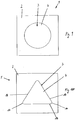
- FIG. 1 shows a closable inspection opening 1 for drywall.
- the inspection opening 1 is designed for use in a ceiling construction.
- the inspection opening 1 comprises a plate 2 for integration of the inspection opening 1 in the drywall system.
- the plate 2 is provided with an opening 3 in which a lid 4 for covering the opening 3 is removably arranged.
- the lid 4 is formed congruent to the opening 3, so that only a small circumferential gap between the plate 2 and 4 lid results.
- the lid 4 is positively held in the opening 3, wherein the positive connection is designed so that the lid 4 is held solely in the plate 2 due to gravity.
- Plate 2 and cover 4 consist in this embodiment of plasterboard.
- plate 2 and cover 4 can also be made of wood and wood-based materials, such as wood fibers, wood chips, in particular processed into chipboard and chipboard (OSB); Gypsum fiber boards and / or cement materials and / or metallic materials, especially in sheet form. Combinations of the aforementioned materials are conceivable.
- FIG. 2 shows the in FIG. 1 described revision opening 1, wherein in this illustration the lid 4 is shown removed from the opening 3.
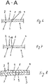
- FIGS. 3 to 8 The figures each show sections in cross section the Platte2 and the lid 4.
- the plate 2 and the lid 4 each have a first main page 5 and a second main page 6 and the opening 3 has a circumferential opening edge 7 and the lid 4 has a peripheral lid edge 8, wherein the opening edge 7 is formed so that the cross-sectional area of the opening 3 on the first main side 5 is smaller than the cross-sectional area of the second main side 6.
- the lid edge 8 is formed in that the cross-sectional area of the lid 4 on the first main side 5 is greater than the cross-sectional area on the second main side 6.
- the first main side 5 points in the direction of the room and the second main side 6 points in the direction of the ceiling.
- the opening edge 7 and the lid edge 8 are formed congruent to each other.
- the figures also show that the opening edge 7 and the lid edge 8 are profiled, wherein the opening edge 7 and the lid edge 8 viewed in cross section at least partially overlap each other.
- Due to the rectangular opening 3 of the plate 2 and the lid 4 straight portions 14 are provided and the straight portions 14 of the plate 2 and / or lid 4 are connected via rounded portions 10.
- the rounded portions 10 form a radius which, depending on the size of the opening 3 is between 1 cm and 10 cm.
- FIG. 3 shows an embodiment of an inspection opening 1 in which from the opening edge 7 and the lid edge 8 each have a step 9 are formed.
- the opening edge 7 and the lid edge 8 are formed as a slope.
- FIGS. 6 and 7 show embodiments in which the opening edge 7 and the lid edge 8 sections are formed vertically, wherein from the lid edge 8, a circumferential nose 13 is formed, which projects in the direction of the plate 2 and engages in a congruent profiling in the opening edge 7.
- the nose 13 is rounded.
- FIG. 8 shows an embodiment of the inspection opening 1 in which the plate 2 and the cover 4 consists of a doubled mounting plate.
- the mounting plates are cut so that at the edges 7, 8 each form a step 9, so that the first main page 5 associated plate of the lid 4 rests on the second main page 6 associated plate of the frame 2.
- FIG. 9 shows a variant of the above-described inspection opening 1, wherein the opening 3 and the lid 4 are circular.
- FIG. 10 shows a further variant of the above-described inspection opening 1, wherein the opening 3 and the lid 4 are triangular.
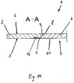
- FIG. 11 shows in section a further embodiment of the above described inspection opening 1, in which the lid 4 is provided on each side with a respective tab 11 made of sheet metal, which protrudes beyond the lid edge 8.
- the tabs 11 are firmly bonded to the lid 4.
- the plate 2 is provided on each side of the opening 3 with at least one retaining means 12, which are placed so that they are connectable to the tab 11.
- the holding means 12 is designed here as a magnet.
- the embodiment shown here is particularly suitable for wall constructions, since the lid 4 is fixed by the positive connection between the opening edge 7 and cover edge 8 in a predetermined position and is held by the connection of tab 11 and retaining means 12 in the opening 3.
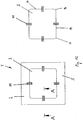
- FIG. 12 shows the in FIG. 11 described embodiment in plan view.
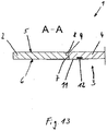
- FIG. 13 shows in section a further embodiment of the above-described inspection opening 1, in which the plate 2 is provided on each side with a respective tab 11 made of sheet metal, which partially covers the opening 3.
- the tabs 4 are firmly bonded to the plate 2.
- the lid 4 is provided on each side with at least one holding means 12, which are placed so that they are connectable to the tab 11.
- the holding means 12 is designed here as a magnet.
- the embodiment shown here is particularly suitable for wall constructions, since the lid 4 is fixed by the positive connection between the opening edge 7 and cover edge 8 in a predetermined position and is held by the connection of tab 11 and retaining means 12 in the opening 3.
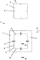
- FIG. 14 shows the in FIG. 13 described embodiment in plan view.
Landscapes
- Engineering & Computer Science (AREA)
- Architecture (AREA)
- Civil Engineering (AREA)
- Structural Engineering (AREA)
- Building Environments (AREA)
- Underground Structures, Protecting, Testing And Restoring Foundations (AREA)
Description
- Die Erfindung betrifft eine Verschließbare Revisionsöffnung für den Trockenbau, umfassend eine Platte mit einer Öffnung und einem Deckel zum Abdecken der Öffnung, wobei die Platte einen die Öffnung begrenzenden Öffnungsrand und der Deckel einen Deckelrand aufweist.
- Trockenbausysteme ermöglichen die Herstellung von Konstruktionen für den Innenausbau, beispielsweise bei der Erstellung von Wänden und Decken. Hierbei werden industrielle Halbzeuge, wie Gipskartonplatten und Metallprofile, in trockener Bauweise eingesetzt. Auf diese Weise lassen sich insbesondere nichttragende Innenwände, Trennwände und Deckenkonstruktionen, wie abgehängte Decken kostengünstig und schnell herstellen. Diese Konstruktionen beinhalten häufig Installationen, beispielsweise Elektro-, Lüftungs- und Sanitärinstallationen. Diese sind nach Fertigstellung der Konstruktion in dem Trockenbausystem verborgen. Um die Installationen dennoch zu Wartungs- und Reparaturzwecken erreichen zu können, sind Revisionsöffnungen bekannt, die in einer Wand oder Decke vorgesehen sind und einen Einblick und Eingriff in das Innere der Konstruktion erlauben. Diese Revisionsöffnungen weisen meist einen Deckel auf, der über ein Scharnier mit einem Rahmen verbunden ist. Der Rahmen wird in die Wand oder Decke integriert und kann mit Platten, beispielsweise Gipskartonplatten versehen werden. Dabei existieren unterschiedliche Ausgestaltungen der Revisionsöffnungen, je nachdem ob diese zur Montage in der Decke oder in der Wand vorgesehen sind. Siehe zum Beispiel
EP 1 911 496 A2 . - Die als Klappe ausgebildeten Revisionsöffnungen weisen den Nachteil auf, dass sie aufwendig in der Herstellung und daher teuer sind. Des Weiteren weisen sie ein vergleichsweise hohes Gewicht auf.
- Der Erfindung liegt die Aufgabe zugrunde, eine verschließbare Revisionsöffnung zu entwickeln, die einfach in der Herstellung und kostengünstig ist und ein geringes Gewicht aufweist.
- Diese Aufgabe wird mit den Merkmalen von Anspruch 1 gelöst. Auf vorteilhafte Ausgestaltungen nehmen die Unteransprüche Bezug.
- Zur Lösung der Aufgabe ist zwischen dem Öffnungsrand und dem Deckelrand ein Formschluss derart ausgebildet, dass der Deckel im montierten Zustand in der Öffnung gehalten ist. Durch den Formschluss hält der Deckel selbsttätig in der Öffnung, wobei keine zusätzlichen Halteelemente erforderlich sind. Insbesondere bei Einsatz der Revisionsöffnung in einer Deckenkonstruktion hält der Deckel selbsttätig aufgrund der Schwerkraft in der Öffnung. Dadurch, dass keine zusätzlichen Halteelemente oder derartiges erforderlich sind, weist die Revisionsöffnung nur sehr wenige Bauteile auf, nämlich in der einfachsten Ausführung im Wesentlichen nur die Platte und den Deckel. Ein separater Rahmen zur Versteifung und zum Aufnehmen von Scharnieren und Befestigungselementen kann entfallen und ermöglicht eine rahmenlose Ausgestaltung der Platte. Dadurch ist die Revisionsöffnung besonders einfach und kostengünstig herstellbar und sie weist ein besonders geringes Gewicht auf. Vorzugsweise ergibt sich der Formschluss nur durch die Formgebung von Platte und Deckel, so dass zusätzliche Formschlusselemente entfallen können. Ein weiterer Vorteil der erfindungsgemäßen verschließbaren Revisionsöffnung ist deren geringe Bauhöhe. Die Bauhöhe der Revisionsöffnung wird durch die Bauhöhe von Platte und Deckel vorgegeben. Vorzugsweise entspricht die Höhe der Platte der Höhe des übrigen Verkleidungsmaterials mit dem der Trockenbau verkleidet wird. Dadurch kann die Revisionsöffnung auch dort eingesetzt werden, wo nur sehr begrenzt Bauraum zur Verfügung steht.
- Die Platte und der Deckel können jeweils eine erste und eine zweite Hauptseite aufweisen und der Öffnungsrand kann so ausgebildet sein, dass die Querschnittsfläche der Öffnung auf der ersten Hauptseite kleiner ist als die Querschnittsfläche der zweiten Hauptseite. Bei dieser Ausgestaltung ist der Deckelrand so ausgebildet, dass die Querschnittsfläche des Deckels auf der ersten Hauptseite größer ist als die Querschnittsfläche auf der zweiten Hauptseite. Vorzugsweise entspricht die Querschnittsfläche der ersten Hauptseite der Öffnung der Querschnittsfläche der ersten Hauptseite des Deckels und die Querschnittsfläche der zweiten Hauptseite der Öffnung entspricht der Querschnittsfläche der zweiten Hauptseite des Deckels. Zum Auflegen des Deckels wird dieser ausgehend von dem der zweiten Hauptseite der Öffnung zugeordneten Raum in der Öffnung plaziert. Aufgrund des kleineren Querschnitts der Öffnung auf der ersten Hauptseite kann der Deckel nicht durch die Öffnung hindurchfallen und ist, bei einer Deckenkonstruktion, aufgrund der Schwerkraft selbsttätig in der Öffnung gehalten.
- Der Öffnungsrand und der Deckelrand sind deckungsgleich zueinander ausgebildet. Dadurch ergibt sich ein besonders sicherer Formschluss, so dass der Deckel zum einen sicher in der Öffnung gehalten ist und zum anderen nicht in der Öffnung verkantet. Vorteilhaft ist auch, dass sich nur ein kleiner Spalt zwischen Platte und Deckel ausbildet.
- Der Öffnungsrand und der Deckelrand können profiliert sein, wobei die Profilierung derart ausgestaltet ist, dass sich der Öffnungsrand und der Deckelrand im Querschnitt betrachtet zumindest abschnittsweise einander überdecken. Dazu können aus dem Öffnungsrand und/oder dem Deckelrand zumindest eine oder mehrere Nasen ausgebildet sein. Vorzugsweise ist eine Nase umlaufend ausgebildet. Die Nasen können mit verschiedenen Radien versehen sein. Dabei ergibt sich eine große Überdeckung und damit ein sicherer Halt für den Deckel. In einer anderen Ausgestaltung können der Öffnungsrand und der Deckelrand als Schräge ausgebildet sein. Eine derartige Form ist besonders einfach herstellbar. Ferner ist denkbar, dass aus dem Öffnungsrand und dem Deckelrand jeweils wenigstens eine Stufe ausgebildet sind. Dabei rastet der Deckel besonders definiert in der Öffnung ein und kann nicht verkanten. Öffnungsrand und Deckelrand können auch so ausgebildet sein, dass mehrere oder alle der zuvor genannten Gestaltungselemente kombiniert sind. Die vorbeschriebenen Ausgestaltungen weisen jeweils den Vorteil auf, dass der Deckel bündig mit der Platte abschließt und der Deckel insbesondere nicht über eine der beiden Hauptseiten der Platte heraussteht. Des Weiteren ist die Fuge, die durch den Öffnungsrand und den Deckelrand gebildet ist, bei dieser Ausgestaltung besonders rauchdicht, weil sich eine Art Labyrinth ergibt.
- Die Öffnung und der Deckel können dreieckig, rechteckig oder vieleckig ausgebildet sein. Dreieckige Deckel sind besonders handlich und durch rechteckige Öffnungen sind verborgene Installationen besonders gut zu erreichen. Bei rechteckigen Öffnungen und Deckeln, insbesondere wenn sie nicht quadratisch ausgebildet sind, kann der Deckel durch die Öffnung hindurch einfach entnommen werden.
- Aufgrund der rechteckigen, dreieckigen oder vieleckigen Grundform der Öffnung der Platte und des Deckels können gerade Abschnitte vorgesehen sein und die geraden Abschnitte von Platte und/oder Deckel können über abgerundete Abschnitte verbunden sein. Bei Verwendung spröder Materialien besteht eine erhöhte Bruchneigung in scharfkantigen Abschnitt, insbesondere wenn gerade Abschnitt und einem spitzen Winkel aufeinander treffen. Um die Bruchneigung zu reduzieren sind die geraden Abschnitt über abgerundete Abschnitte miteinander verbunden. Diese abgerundeten Abschnitte sind mit einem Radius versehen. Vorteilhafterweise beträgt der Radius zwischen 1cm und 10cm. Radien in diesem Bereich reduzieren die Bruchneigung, ohne die Öffnung zu stark zu verkleinern.
- Die Öffnung und der Deckel können jeweils eine kreisförmige oder eine ovale Grundform aufweisen. Bei einer kreisförmigen Ausgestaltung wird das spitzwinklige Aufeinandertreffen gerader Abschnitte vermieden, was insbesondere bei Verwendung spröder Materialien wie Gips relevant ist. Diese weisen insbesondere in scharfkantigen Ecken eine stark erhöhte Bruchneigung auf.
- Der Deckel kann mit zumindest einer Lasche versehen sein, die über den weiteren Rand des Deckels hinausragt. Dabei ist die Lasche auf der ersten Hauptseite des Deckels angeordnet, die die größere Querschnittsfläche aufweist. Die Lasche verbessert den Halt des Deckels in der Öffnung. Die Lasche kann stoffschlüssig, beispielsweise durch eine Klebeverbindung, oder kraftschlüssig, beispielsweise mittels einer Schraubverbindung, an dem Deckel befestigt sein.
- Die Platte kann mit zumindest einem Haltemittel versehen sein, welches mit der Lasche verbindbar ist. Das Haltemittel ist dabei so ausgebildet, dass die Verbindung zwischen Haltemittel und Lasche lösbar und wiederverschließbar ist. Diese Ausgestaltung eignet sich insbesondere für Wandkonstruktionen, da bei Wandkonstruktionen der Deckel nicht allein aufgrund der Schwerkraft in der Öffnung fixiert werden kann. Die Fixierung des Deckels in der Öffnung erfolgt dann bei Wandkonstruktionen durch die Verbindung zwischen Lasche und Haltemittel.
- Die Platte kann mit zumindest einer Lasche versehen sein, die die Öffnung teilweise überdeckt. Bei dieser Ausgestaltung ist die Lasche auf der zweiten Hauptseite der Platte angeordnet, die die größere Querschnittsfläche aufweist. Die Lasche verbessert, wie zuvor beschrieben, den Halt des Deckels in der Öffnung. Die Lasche kann stoffschlüssig, beispielsweise durch eine Klebeverbindung, oder kraftschlüssig, beispielsweise mittels einer Schraubverbindung, an dem Deckel befestigt sein.
- Der Deckel kann mit zumindest einem Haltemittel versehen sein, welches mit der Lasche verbindbar ist. Wie zuvor beschrieben ist das Haltemittel dabei so ausgebildet, dass die Verbindung zwischen Haltemittel und Lasche lösbar und wiederverschließbar ist. Diese Ausgestaltung eignet sich insbesondere für Wandkonstruktionen, da bei Wandkonstruktionen der Deckel nicht allein aufgrund der Schwerkraft in der Öffnung fixiert werden kann. Die Fixierung des Deckels in der Öffnung erfolgt dann bei Wandkonstruktionen durch die Verbindung zwischen Lasche und Haltemittel.
- Die Lasche kann aus einem metallischen Werkstoff bestehen. Besonders bevorzugt sind metallische Werkstoffe mit magnetischen Eigenschaften. Laschen aus metallischen Werkstoffen können in geringer Dicke aus kostengünstigen Blechen hergestellt werden. Es ist auch denkbar, die Lasche aus Kunststoff herzustellen.
- Das Haltemittel kann ein Magnet sein. Dieser Magnet kann je nach Ausführung in den Deckel oder in die Platte eingelassen sein und steht dadurch nicht über eine der Hauptseiten hinaus. Der Magnet geht eine besonders einfach herstellbare und vielfach wiederverschließbare Verbindung mit einer aus metallischem Werkstoff hergestellten Lasche ein. Besonders vorteilhaft ist ferner, dass die Verbindung selbsttätig ist und bereits schon bei geringen Abständen wirksam ist, so dass sich der Deckel nach Unterschreiten eines gewissen Abstandes selbsttätig in der Öffnung zentriert. Es sind aber auch andere Haltemittel denkbar. So kann das Haltemittel auch als Klettverschluss ausgebildet sein. Dies ist in Umgebungen vorteilhaft, in denen keine metallischen Werkstoffe verwendet werden dürfen. Hierbei besteht die Lasche aus Kunststoff.
- Platte und Deckel können aus Holz und Holzwerkstoffen, wie Holzfasern, Holzspäne, hier insbesondere verarbeitet zu Spanplatten und Grobspanplatten (OSB); und/oder aus metallischen Werkstoffen, insbesondere in Blechform bestehen. Die vorbeschriebenen Werkstoffe sind zur Verwendung im Trockenbau bekannt.
- Besonders vorteilhaft ist die Ausgestaltung von Platte und Deckel aus Gipskartonplatten, Gipsfaserplatten, Mineralfaserplatten und/oder Zementwerkstoffen. Diese Werkstoffe weisen ein vorteilhaftes Brandschutzverhalten auf und insbesondere die Platte kann gespachtelt oder verputzt werden, so dass sich die Revisionsöffnung, abgesehen von der Fuge zwischen Platte und Deckel fugenlos in den Trockenbau einfügt. Überraschenderweise weisen auch Platten und Deckel aus Gips- oder Zementwerkstoffen trotz der großen Sprödigkeit eine ausreichende Stabilität auf, so dass der Deckel vielfach entfernt und wieder aufgesetzt werden kann. Mineralfaserplatten sind nicht brennbar und weisen vorteilhafte schallschluckende Eigenschaften auf. Daher sind Mineralfaserplatten insbesondere für Deckenkonstruktionen geeignet. Insbesondere kann der Deckel eine oder mehrere übereinander angeordnete Platten der vorerwähnten Art aufweisen. Dadurch ergibt sich ein mehrschichtiger Deckel.
- Eine erfindungsgemäße Deckenkonstruktion beinhaltet eine Revisionsöffnung wie zuvor beschrieben. Insbesondere die Ausgestaltung, bei der der Deckel lediglich in die Öffnung eingelegt ist, ist für eine Deckenkonstruktion geeignet. Diese ist leicht zu bedienen und weist nur wenige Teile auf. Eine vorteilhafte Deckenkonstruktion ist eine abgehängte Decke, bei der Platten in Form von Kassetten in eine Tragkonstruktion eingelegt werden. Hier ist die Revisionsöffnung als Kassette ausgebildet.
- Eine weitere erfindungsgemäße Ausgestaltung betrifft eine Wandkonstruktion mit einer Revisionsöffnung wie zuvor beschrieben. Bei einer Wandkonstruktion ist die Ausgestaltung der Revisionsöffnung mit Laschen und Haltemitteln vorteilhaft, da diese sicher in der Wand gehalten ist.
- Einige Ausführungsbeispiele der erfindungsgemäßen verschließbaren Revisionsöffnung werden nachfolgend anhand der Figuren näher erläutert. Diese zeigen, jeweils schematisch:
- Fig. 1
- eine verschließbare Revisionsöffnung in der Draufsicht;
- Fig. 2
- eine verschließbare Revisionsöffnung in der Draufsicht mit entferntem Deckel;
- Fig. 3 bis Fig. 8
- verschiedene Ausgestaltungen von Öffnungsrand und Deckelrand einer Revisionsöffnung im Querschnitt;
- Fig. 9
- eine Revisionsöffnung mit kreisförmigem Deckel;
- Fig. 10
- eine Revisionsöffnung mit dreieckigem Deckel;
- Fig. 11
- eine Revisionsöffnung mit zusätzlichen Laschen und Haltemitteln;
- Fig. 12
- die in
Fig. 11 dargestellte Revisionsöffnung in der Draufsicht; - Fig. 13
- eine Revisionsöffnung mit zusätzlichen Laschen und Haltemitteln;
- Fig. 14
- die in
Fig. 13 dargestellte Revisionsöffnung in der Draufsicht. -
Figur 1 zeigt eine verschließbare Revisionsöffnung 1 für den Trockenbau. In dieser Ausgestaltung ist die Revisionsöffnung 1 für den Einsatz in einer Deckenkonstruktion ausgebildet. Die Revisionsöffnung 1 umfasst eine Platte 2 zur Einbindung der Revisionsöffnung 1 in das Trockenbausystem. Die Platte 2 ist mit einer Öffnung 3 versehen, in der ein Deckel 4 zum Abdecken der Öffnung 3 herausnehmbar angeordnet ist. Der Deckel 4 ist deckungsgleich zu der Öffnung 3 ausgebildet, so dass sich nur eine kleine umlaufende Fuge zwischen Platte 2 und Deckel 4 ergibt. Der Deckel 4 ist formschlüssig in der Öffnung 3 gehalten, wobei der Formschluss so ausgestaltet ist, dass der Deckel 4 allein aufgrund der Schwerkraft in der Platte 2 gehalten ist. Platte 2 und Deckel 4 bestehen in dieser Ausgestaltung aus Gipskarton. In anderen Ausgestaltungen können Platte 2 und Deckel 4 auch aus Holz und Holzwerkstoffen, wie Holzfasern, Holzspäne, hier insbesondere verarbeitet zu Spanplatten und Grobspanplatten (OSB); Gipsfaserplatten und/oder Zementwerkstoffen und/oder aus metallischen Werkstoffen, insbesondere in Blechform bestehen. Auch Kombinationen der zuvor genannten Werkstoffe sind denkbar. -
Figur 2 zeigt die inFigur 1 beschriebene Revisionsöffnung 1, wobei in dieser Darstellung der Deckel 4 aus der Öffnung 3 entfernt dargestellt ist. - Die
Figuren 3 bis 8 zeigen verschiedene Ausgestaltungen des Öffnungsrandes 7 und des Deckelrandes 8. Die Figuren zeigen jeweils abschnittsweise im Querschnitt die Platte2 und den Deckel 4. Dabei weisen die Platte 2 und der Deckel 4 jeweils eine erste Hauptseite 5 und eine zweite Hauptseite 6 auf und die Öffnung 3 weist einen umlaufenden Öffnungsrand 7 und der Deckel 4 weist einen umlaufenden Deckelrand 8 auf, wobei der Öffnungsrand 7 so ausgebildet ist, dass die Querschnittsfläche der Öffnung 3 auf der ersten Hauptseite 5 kleiner ist als die Querschnittsfläche der zweiten Hauptseite 6. Der Deckelrand 8 ist so ausgebildet, dass die Querschnittsfläche des Deckels 4 auf der ersten Hauptseite 5 größer ist als die Querschnittsfläche auf der zweiten Hauptseite 6. Die erste Hauptseite 5 weist in Richtung des Raums und die zweite Hauptseite 6 weist in Richtung der Decke. Der Öffnungsrand 7 und der Deckelrand 8 sind deckungsgleich zueinander ausgebildet. Die Figuren zeigen ferner, dass der Öffnungsrand 7 und der Deckelrand 8 profiliert sind, wobei sich der Öffnungsrand 7 und der Deckelrand 8 im Querschnitt betrachtet zumindest abschnittsweise einander überdecken. Aufgrund der rechteckigen Öffnung 3 der Platte 2 und des Deckels 4 sind gerade Abschnitte 14 vorgesehen und die geraden Abschnitte 14 von Platte 2 und/oder Deckel 4 sind über abgerundete Abschnitte 10 verbunden. Die abgerundeten Abschnitte 10 bilden einen Radius, der je nach Größe der Öffnung 3 zwischen 1cm und 10cm beträgt. -
Figur 3 zeigt eine Ausgestaltung einer Revisionsöffnung 1 bei der aus dem Öffnungsrand 7 und dem Deckelrand 8 jeweils eine Stufe 9 ausgebildet sind. - Bei der Ausgestaltung gemäß
Figur 4 sind an dem Öffnungsrand 7 und dem Deckelrand 8 jeweils zwei Stufen 9 vorgesehen. - Bei der Ausgestaltung gemäß
Figur 5 sind der Öffnungsrand 7 und der Deckelrand 8 als Schräge ausgebildet. - Die
Figuren 6 und 7 zeigen Ausgestaltungen bei denen der Öffnungsrand 7 und der Deckelrand 8 abschnittsweise senkrecht ausgebildet sind, wobei aus dem Deckelrand 8 eine umlaufende Nase 13 ausgebildet ist, welche in Richtung der Platte 2 ragt und in eine deckungsgleiche Profilierung in dem Öffnungsrand 7 eingreift. Die Nase 13 ist verrundet ausgebildet. -
Figur 8 zeigt eine Ausgestaltung der Revisionsöffnung 1 bei der die Platte 2 und der Deckel 4 aus einer gedoppelten Montageplatte besteht. Dabei sind die Montageplatten so zugeschnitten, dass sich an den Rändern 7, 8 jeweils eine Stufe 9 ausbildet, so dass die der ersten Hauptseite 5 zugeordnete Platte des Deckels 4 auf der der zweiten Hauptseite 6 zugeordneten Platte des Rahmens 2 aufliegt. -
Figur 9 zeigt eine Variante der zuvor beschriebenen Revisionsöffnung 1, wobei die Öffnung 3 und der Deckel 4 kreisförmig ausgebildet sind. -
Figur 10 zeigt eine weitere Variante der zuvor beschriebenen Revisionsöffnung 1, wobei die Öffnung 3 und der Deckel 4 dreieckig ausgebildet sind. -
Figur 11 zeigt im Schnitt eine weitere Ausgestaltung der zuvor beschriebenen Revisionsöffnung 1, bei der der Deckel 4 an jeder Seite mit jeweils einer Lasche 11 aus Blech versehen ist, die über den Deckelrand 8 hinausragt. Die Laschen 11 sind stoffschlüssig an dem Deckel 4 befestigt. Die Platte 2 ist zu jeder Seite der Öffnung 3 mit zumindest einem Haltemittel 12 versehen, welche so plaziert sind, dass sie mit der Lasche 11 verbindbar sind. Das Haltemittel 12 ist hier als Magnet ausgebildet. Die hier gezeigte Ausgestaltung eignet sich insbesondere für Wandkonstruktionen, da der Deckel 4 durch den Formschluss zwischen Öffnungsrand 7 und Deckelrand 8 in einer vorgegebenen Lage fixiert wird und durch die Verbindung von Lasche 11 und Haltemittel 12 in der Öffnung 3 gehalten ist. -
Figur 12 zeigt die inFigur 11 beschriebene Ausgestaltung in der Draufsicht. -
Figur 13 zeigt im Schnitt eine weitere Ausgestaltung der zuvor beschriebenen Revisionsöffnung 1, bei der die Platte 2 an jeder Seite mit jeweils einer Lasche 11 aus Blech versehen ist, die die Öffnung 3 teilweise überdeckt. Die Laschen 4 sind stoffschlüssig an der Platte 2 befestigt. Der Deckel 4 ist an jeder Seite mit zumindest einem Haltemittel 12 versehen, welche so plaziert sind, dass sie mit der Lasche 11 verbindbar sind. Das Haltemittel 12 ist hier als Magnet ausgebildet. Die hier gezeigte Ausgestaltung eignet sich insbesondere für Wandkonstruktionen, da der Deckel 4 durch den Formschluss zwischen Öffnungsrand 7 und Deckelrand 8 in einer vorgegebenen Lage fixiert wird und durch die Verbindung von Lasche 11 und Haltemittel 12 in der Öffnung 3 gehalten ist. -
Figur 14 zeigt die inFigur 13 beschriebene Ausgestaltung in der Draufsicht. -
- 1
- Revisionsöffnung
- 2
- Rahmen
- 3
- Öffnung
- 4
- Deckel
- 5
- erste Hauptseite
- 6
- zweite Hauptseite
- 7
- Öffnungsrand
- 8
- Deckelrand
- 9
- Stufe
- 10
- abgerundeter Abschnitt
- 11
- Lasche
- 12
- Haltemittel
- 13
- Nase
- 14
- gerader Abschnitt
Claims (15)
- Verschließbare Revisionsöffnung (1) für den Trockenbau, umfassend eine Platte (2) mit einer Öffnung (3) und einem Deckel (4) zum Abdecken der Öffnung (3), wobei die Platte (2) einen die Öffnung (3) begrenzenden Öffnungsrand (7) und der Deckel (4) einen Deckelrand (8) aufweist, dadurch gekennzeichnet, dass zwischen dem Öffnungsrand (7) und dem Deckelrand (8) ein Formschluss derart ausgebildet ist, dass der Deckel (4) im montierten Zustand in der Öffnung (3) gehalten ist, wobei der Öffnungsrand (7) und der Deckelrand (8) profiliert sind, wobei die Profilierung derart ausgestaltet ist, dass sich der Öffnungsrand (7) und der Deckelrand (8) im Querschnitt betrachtet zumindest abschnittsweise einander überdecken.
- Revisionsöffnung nach Anspruch 1, dadurch gekennzeichnet, dass die Platte (2) und der Deckel (4) jeweils eine erste Hauptseite (5) und eine zweite Hauptseite (6) aufweisen und dass der Öffnungsrand (7) so ausgebildet ist, dass die Querschnittsfläche der Öffnung (3) auf der ersten Hauptseite (5) größer ist als die Querschnittsfläche der Öffnung (3) der zweiten Hauptseite (6).
- Revisionsöffnung nach Anspruch 2, dadurch gekennzeichnet, dass der Deckelrand (8) so ausgebildet ist, dass die Querschnittsfläche des Deckels (4) auf der ersten Hauptseite (5) größer ist als die Querschnittsfläche des Deckels (4) auf der zweiten Hauptseite (6).
- Revisionsöffnung nach Anspruch 3, dadurch gekennzeichnet, dass der Öffnungsrand (7) und der Deckelrand (8) deckungsgleich zueinander ausgebildet sind.
- Revisionsöffnung nach einem der Ansprüche 1 bis 4, dadurch gekennzeichnet, dass die Öffnung (3) der Platte (2) und der Deckel (4) jeweils eine dreieckige, rechteckige, oder vieleckige Grundform aufweisen.
- Revisionsöffnung nach Anspruch 5, dadurch gekennzeichnet, dass aufgrund der rechteckigen, dreieckigen oder vieleckigen Grundform der Öffnung (3) der Platte (2) und des Deckels (4) gerade Abschnitte (14) vorgesehen sind und dass die geraden Abschnitte (14) von Platte (2) und/ oder Deckel (4) über abgerundete Abschnitte (10) verbunden sind.
- Revisionsöffnung nach einem der Ansprüche 1 bis 4, dadurch gekennzeichnet, dass die Öffnung (3) und der Deckel (4) jeweils eine kreisförmige oder ovale Grundform aufweisen.
- Revisionsöffnung nach einem der Ansprüche 1 bis 7, dadurch gekennzeichnet, dass der Deckel (4) mit zumindest einer Lasche (11) versehen ist, die über den Deckelrand (8) hinausragt.
- Revisionsöffnung nach Anspruch 8, dadurch gekennzeichnet, dass die Platte (2) mit zumindest einem Haltemittel (12) versehen ist, welches mit der Lasche (11) verbindbar ist.
- Revisionsöffnung nach einem der Ansprüche 1 bis 7, dadurch gekennzeichnet, dass die Platte (2) mit zumindest einer Lasche (11) versehen ist, die die Öffnung (3) teilweise überdeckt.
- Revisionsöffnung nach Anspruch 10, dadurch gekennzeichnet, dass der Deckel (4) mit zumindest einem Haltemittel (12) versehen ist, welches mit der Lasche (11) verbindbar ist.
- Revisionsöffnung nach einem der Ansprüche 8 bis 11, dadurch gekennzeichnet, dass die Lasche (11) aus einem metallischen Werkstoff besteht und dass das Haltemittel (12) ein Magnet ist.
- Revisionsöffnung nach einem der Ansprüche 1 bis 10, dadurch gekennzeichnet, dass die Platte (2) und/ oder der Deckel (4) aus Holz und Holzwerkstoffen, Gipskartonplatten, Gipsfaserplatten, Mineralfaserplatten, Zementwerkstoffen und/oder aus metallischen Werkstoffen, insbesondere in Blechform, bestehen.
- Deckenkonstruktion, umfassend eine Revisionsöffnung nach einem der vorherigen Ansprüche.
- Wandkonstruktion, umfassend eine Revisionsöffnung nach einem der vorherigen Ansprüche.
Applications Claiming Priority (2)
| Application Number | Priority Date | Filing Date | Title |
|---|---|---|---|
| DE202010002007U DE202010002007U1 (de) | 2010-02-05 | 2010-02-05 | Verschließbare Revisionsöffnung für den Trockenbau |
| PCT/EP2011/000144 WO2011095275A1 (de) | 2010-02-05 | 2011-01-14 | Verschliessbare revisionsöffnung für den trockenbau |
Publications (2)
| Publication Number | Publication Date |
|---|---|
| EP2531669A1 EP2531669A1 (de) | 2012-12-12 |
| EP2531669B1 true EP2531669B1 (de) | 2016-03-30 |
Family
ID=42115072
Family Applications (1)
| Application Number | Title | Priority Date | Filing Date |
|---|---|---|---|
| EP11703579.0A Active EP2531669B1 (de) | 2010-02-05 | 2011-01-14 | Verschliessbare revisionsöffnung für den trockenbau |
Country Status (7)
| Country | Link |
|---|---|
| EP (1) | EP2531669B1 (de) |
| CN (1) | CN102906357B (de) |
| DE (1) | DE202010002007U1 (de) |
| IL (1) | IL221239A0 (de) |
| RU (2) | RU2012139492A (de) |
| UA (1) | UA109124C2 (de) |
| WO (1) | WO2011095275A1 (de) |
Families Citing this family (10)
| Publication number | Priority date | Publication date | Assignee | Title |
|---|---|---|---|---|
| WO2011141065A1 (de) * | 2010-05-12 | 2011-11-17 | Knauf Gips Kg | BAUPLATTE, INSBESONDERE ZUR DECKENMONTAGE, SOWIE VERFAHREN ZUM ÖFFNEN ODER SCHLIEßEN EINER REVISIONSÖFFNUNG IN EINER BAUPLATTE |
| IT1403393B1 (it) * | 2010-10-29 | 2013-10-17 | Panzieri | Botola di collegamento tra vani adiacenti per edilizia a secco. |
| ITGE20130047A1 (it) * | 2013-05-08 | 2014-11-09 | Pucci Saoro Srl | Dispositivo e kit per la chiusura di cassette tecniche |
| JP6780295B2 (ja) * | 2016-05-27 | 2020-11-04 | ヤマハ株式会社 | 天井パネル及び組立式防音室 |
| WO2018224116A1 (en) | 2017-06-08 | 2018-12-13 | Knauf Gips Kg | Device for closing off an opening, in particular an inspection opening, and construction kit for the same |
| EP3635195B1 (de) | 2017-06-08 | 2025-04-16 | Knauf Gips KG | Vorrichtung zum verschliessen einer prüföffnung und verfahren zum einsetzen einer vorrichtung des besagten typs |
| EP3635194B1 (de) | 2017-06-08 | 2025-08-06 | Knauf Gips KG | Vorrichtung zum verschliessen einer öffnung, insbesondere einer inspektionsöffnung, in einer trockenbaustruktur |
| CN109838025A (zh) * | 2019-01-26 | 2019-06-04 | 广州市中港建设工程有限公司 | 室内组合式吊挂天花结构及其方法 |
| DE102021120150B3 (de) * | 2021-08-03 | 2023-01-26 | Schlosserei Klaus Schuler GmbH | Vorrichtung zum Aufnehmen eines Pflanzentopfs |
| GB2642752A (en) * | 2024-07-19 | 2026-01-21 | Baccarini Tony | Access panel |
Family Cites Families (3)
| Publication number | Priority date | Publication date | Assignee | Title |
|---|---|---|---|---|
| FR2451430B1 (fr) * | 1979-03-16 | 1986-03-28 | Edac Sa | Cadre metallique pour trappe de plafond ou trappe d'acces aux gaines de ventilation ou similaires et profile pour sa realisation |
| DE3544847C2 (de) * | 1985-12-18 | 1997-01-23 | Eckart Roth | Einbaurahmen |
| AT504833B1 (de) * | 2006-10-10 | 2009-09-15 | Kamleithner Maly Uta Ing Mag | Brandschutz-verschluss |
-
2010
- 2010-02-05 DE DE202010002007U patent/DE202010002007U1/de not_active Expired - Lifetime
-
2011
- 2011-01-14 RU RU2012139492/03A patent/RU2012139492A/ru unknown
- 2011-01-14 EP EP11703579.0A patent/EP2531669B1/de active Active
- 2011-01-14 RU RU2015118161/03A patent/RU2015118161A/ru not_active Application Discontinuation
- 2011-01-14 UA UAA201210481A patent/UA109124C2/uk unknown
- 2011-01-14 WO PCT/EP2011/000144 patent/WO2011095275A1/de not_active Ceased
- 2011-01-14 CN CN201180009232.8A patent/CN102906357B/zh not_active Expired - Fee Related
-
2012
- 2012-08-01 IL IL221239A patent/IL221239A0/en unknown
Also Published As
| Publication number | Publication date |
|---|---|
| CN102906357A (zh) | 2013-01-30 |
| EP2531669A1 (de) | 2012-12-12 |
| RU2015118161A (ru) | 2015-12-10 |
| WO2011095275A1 (de) | 2011-08-11 |
| CN102906357B (zh) | 2016-02-03 |
| UA109124C2 (uk) | 2015-07-27 |
| RU2015118161A3 (de) | 2018-10-12 |
| IL221239A0 (en) | 2012-10-31 |
| DE202010002007U1 (de) | 2010-04-22 |
| RU2012139492A (ru) | 2014-03-10 |
Similar Documents
| Publication | Publication Date | Title |
|---|---|---|
| EP2531669B1 (de) | Verschliessbare revisionsöffnung für den trockenbau | |
| DE202015105980U1 (de) | Abdeckung für eine Revisionsöffnung | |
| DE202018105652U1 (de) | Raumzelle für ein Raum-in-Raum-System | |
| EP2531668B1 (de) | VERSCHLIEßBARE BRANDSCHUTZÖFFNUNG FÜR DEN TROCKENBAU | |
| EP3012395A1 (de) | Streifenförmiges Stütz- und Isolierelement zur Abstützung und Isolierung eines Fensterrahmens | |
| EP0044055A1 (de) | Sanitärzelle aus vorgefertigten Bauelementen | |
| EP3385466B1 (de) | Profil zur errichtung einer nicht tragenden aussenwand für gebäude, eine nicht tragende aussenwand für ein gebäude die wenigstens ein solches profil umfasst sowie ein gebäude welches eine solche nicht tragende aussenwand umfasst | |
| DE202007007553U1 (de) | Plattenelement | |
| EP2550413B2 (de) | Verschliessbare Revisionsöffnung für den Trockenbau | |
| DE202012100380U1 (de) | Flächenbündige Türeinheit | |
| EP1591597A1 (de) | Gipskartonständerwand | |
| DE3120410A1 (de) | Montage-unterdecke | |
| EP0013988B1 (de) | Lösbare Verbindung zwischen zwei schalen- od. plattenförmigen Bauteilen, z.B. für Wände, Böden, Decken od. dgl. | |
| EP4502443A1 (de) | Brandabschottung für leitungen in gebäuden | |
| DE102004053014B3 (de) | Türzarge, insbesondere für Fahrschachttüren | |
| DE9214484U1 (de) | Vorrichtung zum abgewinkelten Verbinden vorzugsweise flächiger Teile | |
| DE102010045776A1 (de) | System zum Abtrennen von mindestens zwei Räumen und Schließelementaufbau | |
| EP3456901B1 (de) | Einbaukasten sowie eine entsprechende montageanordnung und ein entsprechender bausatz | |
| DE202018100067U1 (de) | Aufnahmevorrichtung zum Einbau in einen Mauerwerksverbund | |
| EP4603650A1 (de) | Unterdecke | |
| AT512182B1 (de) | Decke | |
| DE10000171B4 (de) | Dämpfungselement mit Verbindungselementen zur akustisch entkoppelten Verbindungmit Bauteilen | |
| DE2305642A1 (de) | Wandelement fuer selbst tragende trennwaende | |
| DE10132766A1 (de) | Einrichtung zur nachträglichen Wärmeisolierung von Hohlräumen | |
| DE202009007676U1 (de) | Revisionsvorrichtung |
Legal Events
| Date | Code | Title | Description |
|---|---|---|---|
| PUAI | Public reference made under article 153(3) epc to a published international application that has entered the european phase |
Free format text: ORIGINAL CODE: 0009012 |
|
| 17P | Request for examination filed |
Effective date: 20120814 |
|
| AK | Designated contracting states |
Kind code of ref document: A1 Designated state(s): AL AT BE BG CH CY CZ DE DK EE ES FI FR GB GR HR HU IE IS IT LI LT LU LV MC MK MT NL NO PL PT RO RS SE SI SK SM TR |
|
| DAX | Request for extension of the european patent (deleted) | ||
| GRAP | Despatch of communication of intention to grant a patent |
Free format text: ORIGINAL CODE: EPIDOSNIGR1 |
|
| INTG | Intention to grant announced |
Effective date: 20150811 |
|
| GRAS | Grant fee paid |
Free format text: ORIGINAL CODE: EPIDOSNIGR3 |
|
| GRAA | (expected) grant |
Free format text: ORIGINAL CODE: 0009210 |
|
| AK | Designated contracting states |
Kind code of ref document: B1 Designated state(s): AL AT BE BG CH CY CZ DE DK EE ES FI FR GB GR HR HU IE IS IT LI LT LU LV MC MK MT NL NO PL PT RO RS SE SI SK SM TR |
|
| REG | Reference to a national code |
Ref country code: GB Ref legal event code: FG4D Free format text: NOT ENGLISH |
|
| REG | Reference to a national code |
Ref country code: CH Ref legal event code: EP |
|
| REG | Reference to a national code |
Ref country code: AT Ref legal event code: REF Ref document number: 785589 Country of ref document: AT Kind code of ref document: T Effective date: 20160415 |
|
| REG | Reference to a national code |
Ref country code: IE Ref legal event code: FG4D Free format text: LANGUAGE OF EP DOCUMENT: GERMAN |
|
| REG | Reference to a national code |
Ref country code: DE Ref legal event code: R096 Ref document number: 502011009266 Country of ref document: DE |
|
| REG | Reference to a national code |
Ref country code: LT Ref legal event code: MG4D |
|
| PG25 | Lapsed in a contracting state [announced via postgrant information from national office to epo] |
Ref country code: NO Free format text: LAPSE BECAUSE OF FAILURE TO SUBMIT A TRANSLATION OF THE DESCRIPTION OR TO PAY THE FEE WITHIN THE PRESCRIBED TIME-LIMIT Effective date: 20160630 Ref country code: FI Free format text: LAPSE BECAUSE OF FAILURE TO SUBMIT A TRANSLATION OF THE DESCRIPTION OR TO PAY THE FEE WITHIN THE PRESCRIBED TIME-LIMIT Effective date: 20160330 Ref country code: GR Free format text: LAPSE BECAUSE OF FAILURE TO SUBMIT A TRANSLATION OF THE DESCRIPTION OR TO PAY THE FEE WITHIN THE PRESCRIBED TIME-LIMIT Effective date: 20160701 Ref country code: HR Free format text: LAPSE BECAUSE OF FAILURE TO SUBMIT A TRANSLATION OF THE DESCRIPTION OR TO PAY THE FEE WITHIN THE PRESCRIBED TIME-LIMIT Effective date: 20160330 |
|
| REG | Reference to a national code |
Ref country code: NL Ref legal event code: MP Effective date: 20160330 |
|
| PG25 | Lapsed in a contracting state [announced via postgrant information from national office to epo] |
Ref country code: LT Free format text: LAPSE BECAUSE OF FAILURE TO SUBMIT A TRANSLATION OF THE DESCRIPTION OR TO PAY THE FEE WITHIN THE PRESCRIBED TIME-LIMIT Effective date: 20160330 Ref country code: LV Free format text: LAPSE BECAUSE OF FAILURE TO SUBMIT A TRANSLATION OF THE DESCRIPTION OR TO PAY THE FEE WITHIN THE PRESCRIBED TIME-LIMIT Effective date: 20160330 Ref country code: RS Free format text: LAPSE BECAUSE OF FAILURE TO SUBMIT A TRANSLATION OF THE DESCRIPTION OR TO PAY THE FEE WITHIN THE PRESCRIBED TIME-LIMIT Effective date: 20160330 Ref country code: SE Free format text: LAPSE BECAUSE OF FAILURE TO SUBMIT A TRANSLATION OF THE DESCRIPTION OR TO PAY THE FEE WITHIN THE PRESCRIBED TIME-LIMIT Effective date: 20160330 |
|
| PG25 | Lapsed in a contracting state [announced via postgrant information from national office to epo] |
Ref country code: NL Free format text: LAPSE BECAUSE OF FAILURE TO SUBMIT A TRANSLATION OF THE DESCRIPTION OR TO PAY THE FEE WITHIN THE PRESCRIBED TIME-LIMIT Effective date: 20160330 |
|
| PG25 | Lapsed in a contracting state [announced via postgrant information from national office to epo] |
Ref country code: PL Free format text: LAPSE BECAUSE OF FAILURE TO SUBMIT A TRANSLATION OF THE DESCRIPTION OR TO PAY THE FEE WITHIN THE PRESCRIBED TIME-LIMIT Effective date: 20160330 Ref country code: EE Free format text: LAPSE BECAUSE OF FAILURE TO SUBMIT A TRANSLATION OF THE DESCRIPTION OR TO PAY THE FEE WITHIN THE PRESCRIBED TIME-LIMIT Effective date: 20160330 Ref country code: IS Free format text: LAPSE BECAUSE OF FAILURE TO SUBMIT A TRANSLATION OF THE DESCRIPTION OR TO PAY THE FEE WITHIN THE PRESCRIBED TIME-LIMIT Effective date: 20160730 |
|
| PG25 | Lapsed in a contracting state [announced via postgrant information from national office to epo] |
Ref country code: RO Free format text: LAPSE BECAUSE OF FAILURE TO SUBMIT A TRANSLATION OF THE DESCRIPTION OR TO PAY THE FEE WITHIN THE PRESCRIBED TIME-LIMIT Effective date: 20160330 Ref country code: SM Free format text: LAPSE BECAUSE OF FAILURE TO SUBMIT A TRANSLATION OF THE DESCRIPTION OR TO PAY THE FEE WITHIN THE PRESCRIBED TIME-LIMIT Effective date: 20160330 Ref country code: ES Free format text: LAPSE BECAUSE OF FAILURE TO SUBMIT A TRANSLATION OF THE DESCRIPTION OR TO PAY THE FEE WITHIN THE PRESCRIBED TIME-LIMIT Effective date: 20160330 Ref country code: PT Free format text: LAPSE BECAUSE OF FAILURE TO SUBMIT A TRANSLATION OF THE DESCRIPTION OR TO PAY THE FEE WITHIN THE PRESCRIBED TIME-LIMIT Effective date: 20160801 Ref country code: CZ Free format text: LAPSE BECAUSE OF FAILURE TO SUBMIT A TRANSLATION OF THE DESCRIPTION OR TO PAY THE FEE WITHIN THE PRESCRIBED TIME-LIMIT Effective date: 20160330 Ref country code: SK Free format text: LAPSE BECAUSE OF FAILURE TO SUBMIT A TRANSLATION OF THE DESCRIPTION OR TO PAY THE FEE WITHIN THE PRESCRIBED TIME-LIMIT Effective date: 20160330 |
|
| PG25 | Lapsed in a contracting state [announced via postgrant information from national office to epo] |
Ref country code: IT Free format text: LAPSE BECAUSE OF FAILURE TO SUBMIT A TRANSLATION OF THE DESCRIPTION OR TO PAY THE FEE WITHIN THE PRESCRIBED TIME-LIMIT Effective date: 20160330 |
|
| REG | Reference to a national code |
Ref country code: DE Ref legal event code: R097 Ref document number: 502011009266 Country of ref document: DE |
|
| PG25 | Lapsed in a contracting state [announced via postgrant information from national office to epo] |
Ref country code: DK Free format text: LAPSE BECAUSE OF FAILURE TO SUBMIT A TRANSLATION OF THE DESCRIPTION OR TO PAY THE FEE WITHIN THE PRESCRIBED TIME-LIMIT Effective date: 20160330 |
|
| PLBE | No opposition filed within time limit |
Free format text: ORIGINAL CODE: 0009261 |
|
| STAA | Information on the status of an ep patent application or granted ep patent |
Free format text: STATUS: NO OPPOSITION FILED WITHIN TIME LIMIT |
|
| 26N | No opposition filed |
Effective date: 20170103 |
|
| PG25 | Lapsed in a contracting state [announced via postgrant information from national office to epo] |
Ref country code: SI Free format text: LAPSE BECAUSE OF FAILURE TO SUBMIT A TRANSLATION OF THE DESCRIPTION OR TO PAY THE FEE WITHIN THE PRESCRIBED TIME-LIMIT Effective date: 20160330 Ref country code: BE Free format text: LAPSE BECAUSE OF NON-PAYMENT OF DUE FEES Effective date: 20170131 |
|
| REG | Reference to a national code |
Ref country code: CH Ref legal event code: PL |
|
| GBPC | Gb: european patent ceased through non-payment of renewal fee |
Effective date: 20170114 |
|
| PG25 | Lapsed in a contracting state [announced via postgrant information from national office to epo] |
Ref country code: MC Free format text: LAPSE BECAUSE OF FAILURE TO SUBMIT A TRANSLATION OF THE DESCRIPTION OR TO PAY THE FEE WITHIN THE PRESCRIBED TIME-LIMIT Effective date: 20160330 |
|
| REG | Reference to a national code |
Ref country code: FR Ref legal event code: ST Effective date: 20170929 |
|
| PG25 | Lapsed in a contracting state [announced via postgrant information from national office to epo] |
Ref country code: LI Free format text: LAPSE BECAUSE OF NON-PAYMENT OF DUE FEES Effective date: 20170131 Ref country code: FR Free format text: LAPSE BECAUSE OF NON-PAYMENT OF DUE FEES Effective date: 20170131 Ref country code: CH Free format text: LAPSE BECAUSE OF NON-PAYMENT OF DUE FEES Effective date: 20170131 |
|
| REG | Reference to a national code |
Ref country code: IE Ref legal event code: MM4A |
|
| PG25 | Lapsed in a contracting state [announced via postgrant information from national office to epo] |
Ref country code: GB Free format text: LAPSE BECAUSE OF NON-PAYMENT OF DUE FEES Effective date: 20170114 Ref country code: LU Free format text: LAPSE BECAUSE OF NON-PAYMENT OF DUE FEES Effective date: 20170114 |
|
| REG | Reference to a national code |
Ref country code: BE Ref legal event code: MM Effective date: 20170131 |
|
| PG25 | Lapsed in a contracting state [announced via postgrant information from national office to epo] |
Ref country code: IE Free format text: LAPSE BECAUSE OF NON-PAYMENT OF DUE FEES Effective date: 20170114 |
|
| REG | Reference to a national code |
Ref country code: AT Ref legal event code: MM01 Ref document number: 785589 Country of ref document: AT Kind code of ref document: T Effective date: 20170114 |
|
| PG25 | Lapsed in a contracting state [announced via postgrant information from national office to epo] |
Ref country code: AT Free format text: LAPSE BECAUSE OF NON-PAYMENT OF DUE FEES Effective date: 20170114 |
|
| PG25 | Lapsed in a contracting state [announced via postgrant information from national office to epo] |
Ref country code: MT Free format text: LAPSE BECAUSE OF FAILURE TO SUBMIT A TRANSLATION OF THE DESCRIPTION OR TO PAY THE FEE WITHIN THE PRESCRIBED TIME-LIMIT Effective date: 20160330 |
|
| PG25 | Lapsed in a contracting state [announced via postgrant information from national office to epo] |
Ref country code: AL Free format text: LAPSE BECAUSE OF FAILURE TO SUBMIT A TRANSLATION OF THE DESCRIPTION OR TO PAY THE FEE WITHIN THE PRESCRIBED TIME-LIMIT Effective date: 20160330 |
|
| PG25 | Lapsed in a contracting state [announced via postgrant information from national office to epo] |
Ref country code: HU Free format text: LAPSE BECAUSE OF FAILURE TO SUBMIT A TRANSLATION OF THE DESCRIPTION OR TO PAY THE FEE WITHIN THE PRESCRIBED TIME-LIMIT; INVALID AB INITIO Effective date: 20110114 |
|
| PG25 | Lapsed in a contracting state [announced via postgrant information from national office to epo] |
Ref country code: BG Free format text: LAPSE BECAUSE OF FAILURE TO SUBMIT A TRANSLATION OF THE DESCRIPTION OR TO PAY THE FEE WITHIN THE PRESCRIBED TIME-LIMIT Effective date: 20160330 |
|
| PG25 | Lapsed in a contracting state [announced via postgrant information from national office to epo] |
Ref country code: CY Free format text: LAPSE BECAUSE OF NON-PAYMENT OF DUE FEES Effective date: 20160330 |
|
| PG25 | Lapsed in a contracting state [announced via postgrant information from national office to epo] |
Ref country code: MK Free format text: LAPSE BECAUSE OF FAILURE TO SUBMIT A TRANSLATION OF THE DESCRIPTION OR TO PAY THE FEE WITHIN THE PRESCRIBED TIME-LIMIT Effective date: 20160330 |
|
| P01 | Opt-out of the competence of the unified patent court (upc) registered |
Effective date: 20230822 |
|
| PGFP | Annual fee paid to national office [announced via postgrant information from national office to epo] |
Ref country code: DE Payment date: 20260128 Year of fee payment: 16 |
|
| PGFP | Annual fee paid to national office [announced via postgrant information from national office to epo] |
Ref country code: TR Payment date: 20260112 Year of fee payment: 16 |