EP2531808B1 - Steinbrechkartusche und zündkapsel - Google Patents
Steinbrechkartusche und zündkapsel Download PDFInfo
- Publication number
- EP2531808B1 EP2531808B1 EP11740105.9A EP11740105A EP2531808B1 EP 2531808 B1 EP2531808 B1 EP 2531808B1 EP 11740105 A EP11740105 A EP 11740105A EP 2531808 B1 EP2531808 B1 EP 2531808B1
- Authority
- EP
- European Patent Office
- Prior art keywords
- ignition
- sleeve
- powder charge
- ignition unit
- unit sleeve
- Prior art date
- Legal status (The legal status is an assumption and is not a legal conclusion. Google has not performed a legal analysis and makes no representation as to the accuracy of the status listed.)
- Active
Links
- 239000011435 rock Substances 0.000 title claims description 45
- 239000002775 capsule Substances 0.000 title claims description 38
- 239000000843 powder Substances 0.000 claims description 58
- 238000005336 cracking Methods 0.000 claims description 21
- 239000002360 explosive Substances 0.000 claims description 10
- 239000000463 material Substances 0.000 claims description 10
- 229920003023 plastic Polymers 0.000 claims description 10
- 230000037452 priming Effects 0.000 claims description 9
- 238000004880 explosion Methods 0.000 claims description 5
- 125000006850 spacer group Chemical group 0.000 claims description 4
- 230000000694 effects Effects 0.000 claims description 3
- 125000000449 nitro group Chemical group [O-][N+](*)=O 0.000 claims description 2
- 239000003999 initiator Substances 0.000 claims 5
- 230000000284 resting effect Effects 0.000 claims 1
- 238000004200 deflagration Methods 0.000 description 5
- 238000002485 combustion reaction Methods 0.000 description 4
- DHKHKXVYLBGOIT-UHFFFAOYSA-N acetaldehyde Diethyl Acetal Natural products CCOC(C)OCC DHKHKXVYLBGOIT-UHFFFAOYSA-N 0.000 description 2
- 125000002777 acetyl group Chemical class [H]C([H])([H])C(*)=O 0.000 description 2
- 229920000122 acrylonitrile butadiene styrene Polymers 0.000 description 2
- 238000000034 method Methods 0.000 description 2
- 239000000026 Pentaerythritol tetranitrate Substances 0.000 description 1
- 230000001154 acute effect Effects 0.000 description 1
- 238000005422 blasting Methods 0.000 description 1
- 238000006243 chemical reaction Methods 0.000 description 1
- 229920001577 copolymer Polymers 0.000 description 1
- 238000005474 detonation Methods 0.000 description 1
- 238000010304 firing Methods 0.000 description 1
- 239000012634 fragment Substances 0.000 description 1
- 238000005259 measurement Methods 0.000 description 1
- 238000003825 pressing Methods 0.000 description 1
- 239000003351 stiffener Substances 0.000 description 1
- 238000003860 storage Methods 0.000 description 1
Images


Classifications
-
- F—MECHANICAL ENGINEERING; LIGHTING; HEATING; WEAPONS; BLASTING
- F42—AMMUNITION; BLASTING
- F42B—EXPLOSIVE CHARGES, e.g. FOR BLASTING, FIREWORKS, AMMUNITION
- F42B3/00—Blasting cartridges, i.e. case and explosive
- F42B3/10—Initiators therefor
-
- F—MECHANICAL ENGINEERING; LIGHTING; HEATING; WEAPONS; BLASTING
- F42—AMMUNITION; BLASTING
- F42B—EXPLOSIVE CHARGES, e.g. FOR BLASTING, FIREWORKS, AMMUNITION
- F42B3/00—Blasting cartridges, i.e. case and explosive
- F42B3/02—Blasting cartridges, i.e. case and explosive adapted to be united into assemblies
-
- F—MECHANICAL ENGINEERING; LIGHTING; HEATING; WEAPONS; BLASTING
- F42—AMMUNITION; BLASTING
- F42B—EXPLOSIVE CHARGES, e.g. FOR BLASTING, FIREWORKS, AMMUNITION
- F42B3/00—Blasting cartridges, i.e. case and explosive
- F42B3/10—Initiators therefor
- F42B3/11—Initiators therefor characterised by the material used, e.g. for initiator case or electric leads
-
- F—MECHANICAL ENGINEERING; LIGHTING; HEATING; WEAPONS; BLASTING
- F42—AMMUNITION; BLASTING
- F42B—EXPLOSIVE CHARGES, e.g. FOR BLASTING, FIREWORKS, AMMUNITION
- F42B3/00—Blasting cartridges, i.e. case and explosive
- F42B3/26—Arrangements for mounting initiators; Accessories therefor, e.g. tools
-
- F—MECHANICAL ENGINEERING; LIGHTING; HEATING; WEAPONS; BLASTING
- F42—AMMUNITION; BLASTING
- F42D—BLASTING
- F42D1/00—Blasting methods or apparatus, e.g. loading or tamping
- F42D1/04—Arrangements for ignition
- F42D1/045—Arrangements for electric ignition
-
- F—MECHANICAL ENGINEERING; LIGHTING; HEATING; WEAPONS; BLASTING
- F42—AMMUNITION; BLASTING
- F42D—BLASTING
- F42D3/00—Particular applications of blasting techniques
- F42D3/04—Particular applications of blasting techniques for rock blasting
Definitions
- the invention concerns a rock cracker cartridge
- a rock cracker cartridge comprising a first, outer sleeve with an end wall in a first end and a central opening in a second end which in other respects is closed by a closure member; a substantially cylindrical, second sleeve which is coaxial with the first, outer sleeve and with said central opening and communicates with said central opening and is connected to and extends from said closure member in a main chamber in said first, outer sleeve; and a rock cracker cartridge which fills the space in the main chamber between said first and second sleeves and between the end wall in said first end and the closure member in the second end.
- the invention also concerns an ignition capsule for igniting the rock cracker cartridge, which ignition capsule in combination with a surrounding ignition assembly sleeve defines an explosive ignition assembly in the rock cracker cartridge which is prepared for ignition, said ignition assembly sleeve being an integrated member of the rock cracker cartridge, when the rock cracker cartridge is not yet prepared for ignition, as well as of the rock cracker cartridge when the rock cracker cartridge is prepared for ignition.
- a rock cracker cartridge of the type mentioned in the preamble is disclosed in WO 2009/120139 .
- This cartridge represents a significant contribution to the technical progress within its specific technical field; cracking major stones, usually called boulders, blocks of rock, minor bedrock sections and the like, in such a mode that it can be carried out even very close to buildings or in other environments which normally would require considerable measurements of precaution. It is also an objective of the invention to bring this technical progress a further step forwards. More specifically, it is ab purpose to provide ignition means for the rock cracker cartridge, which satisfy the requirements of lowest Swedish classification for transportation of explosives, transportation class 1,4.
- rock cracker cartridge shall be able to be fired without use of a detonator containing any detonating explosive, such as PENT or the like, which conventional ignition capsules do.
- the unprimed cracker cartridge 1, Fig. 8 comprises a first, outer plastic sleeve 2 and an insert unit 25, Fig.6 and Fig.7 , which in turn consists of a plug 4 and a second, inner sleeve 7.
- the plug 4 and the inner sleeve 7 consist, according to the embodiment, of a hard plastic material, more specifically an acetal plastic material, and still more specifially of an acetal (POM)- copolymer and are mould jointly to form an integrated unit.
- the outer sleeve 2 is, according to the embodiment, made of a so called ABS-plastic, which also is a hard plastic material, and has the shape of an elongated circular-cylindrical tube with a flat end wall.
- the interior of the outer sleeve 2 forms a main chamber 5 which is filled with a cracking powder charge 6, preferably a nitro powder charge (NC-powder), Fig. 9 .
- the plug 4 has a circular-cylindrical outer wall 19, a flat annular end wall 20, which faces the main chamber 5 and is pressed against the powder charge 6, and a tubular portion 31 which defines a through hole 8, which is coaxial with the outer sleeve 2.
- Radial beams 24 extend between the tubular portion 21 and the cylindrical wall. Wedge-shaped, material saving recesses between the beams 24 are designated 23, and an upper flange is designated. On said upper flange there are provided three spacer members 19a, which protrude in the axial direction.
- the sleeve 7, 7a has a comparatively thin wall 13. According to the embodiment, it is about one millimetre thick. It may optionally, in order to make it stiffer, be provided with longitudinal, external stiffeners.
- the outer surface as well as the main portion of the inner surface are quite smooth, which nevertheless affords the ignition assembly sleeve 7a an adequate stiffness but at the same time not a greater rupture resistance than what it maximally may have in order certainly to be broken up when that ignition capsule which shall be described in the following, is ignited, and which in the primed cracking cartridge 1 is accommodated in the space 9 of the ignition assembly sleeve 7a which is denominated priming chamber.
- the pointed nose portion or tip 12 is conical, forming an acute angle. Close to the nose portion 12, the sleeve 7a has an internal constriction 26, which is about 0.2 mm thick in the radial direction and about 5 mm long in the axial direction.
- the plug 4 is pressed with some force into the mouth section of the outer sleeve 2 so far that the flange 22 abuts the upper edge of the outer sleeve 2 and the flat end wall 20 will be pressed against the cracking powder charge 6.
- the inner sleeve, 7, 7a will be pressed into the cracking powder charge 6, which is facilitated by its pointed edge portion or tip 12.
- the quantity of powder in the cracking powder charge 6 is adapted so that the insert 25 can be pressed into the outer sleeve 2 such that the cracking powder charge is compacted to a certain degree, which is advantageous because that prevents the powder from moving to any significant degree during transportation, however, is not compacted so much that the thin wall 13 of the inner sleeve is damaged or is pressed together to any significant degree.
- the interior of the ignition assembly sleeve 7a forms a direct continuation of the through hole 8 in the plug 4 and it also has the same cross section as the hole 8.
- the hole 8 and the inner space in the ignition assembly sleeve 7a in other words are integrated and form said priming chamber 9.
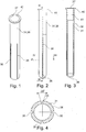
- the ignition capsule 30 consists of an ignition unit sleeve 31, Fig. 1- Fig. 4 , and, in said sleeve 31 an ignition unit 32 consisting of an igniter 33a which can be activated electrically, an ignition powder charge 29 consisting of the same type of NC-powder as the cracking powder charge 6, and an igniter socket 34, to which ignition cables 37 are connected.
- the igniter is of the type which has its normal use in the pyrotechnical field for firing pyrotechnical articles. Igniters of that type are manufactured e.g. by the Czech company META-PYRO, s.r.o., Brno.
- the ignition unit sleeve 31 consists of a hard plastic material, preferably of the same type of ABS-plastic as the outer sleeve 2.
- the thickness, according to the embodiment is the same as of the ignition assembly sleeve 7a, about one millimetre.
- the ignition unit sleeve 31, however, is provided with a number, according to the embodiment of four external grooves 35 which extend from the cupped end portion 36 of the sleeve in the axial direction towards the mouth of the sleeve all the way to at level with the front end of the igniter 33a which is accommodated in the priming chamber 9.
- the ignition unit sleeve 31 has a smooth circular-cylindrical outside surface 38.
- the depth of the grooves 35 exceeds half the wall thickness of the ignition unit sleeve 31, more specifically, the depth is 0.7 mm.
- the mean width of the grooves which widen in the outwards direction, approximately equals the wall thickness of the ignition unit sleeve.
- the outer diameter of the ignition unit sleeve 31 is slightly - about 0.2 mm - smaller than the inner diameter of the ignition assembly sleeve 7a. Its cylindrical length equals the cylindrical length of the ignition assembly sleeve 7a, i.e. it extends all the way to the conical nose portion 12 of the ignition assembly sleeve 7a.
- the ignition capsule 30 can be entered into the ignition assembly sleeve 7a with close fit against the inside surface of the ignition assembly sleeve but without jamming.
- the gap 39 between the two sleeves 31 and 7a amounts to about 0.1 mm according to the embodiment but it may also be slightly smaller or larger.
- the width of the gap should be within the range 0.05 - 0.2 mm.
- the ignition assembly sleeve 7a has a constriction 26 quite close to the conical nose portion 12, which constriction has an extension in the radial direction which is greater than the width of the gap 39.
- the radial extension is about twice as large as the width of the gap or 0.2 mm.
- the ignition unit sleeve 31 has a mouth section 41, Fig. 3 , with an inner diameter which is slightly larger than the main portion of the sleeve 31 and a length adapted to the diameter and length of the socket 34 of the igniter 33a, so that the igniter 33a is secured in the charged ignition capsule 30 through press-fit between the socket 34 and the ignition unit sleeve 31 in the region of the mouth section 41.
- the igniter 33a extends in the ignition capsule 30 from its socket 34 into the ignition powder charge 29 all the way to where the grooves 35 have their rear ends on the outer side of the ignition capsule/ignition unit sleeve.
- the igniter 33a thus is surrounded by and is in intense contact with ignition powder, which, lightly compressed, occupies essentially all available space between the cupped bottom portion 36 of the ignition unit sleeve 31 and the igniter socket 34. Therefore, the contact between the igniter 33a and the ignition powder charge 29 is very good, which promotes a safe ignition of the ignition powder charge when the ignition unit 32 is ignited electrically by means of the igniter 33a.
- the ignition capsule 30 is not an explosive product "in free state", such as for example during transportation and storage, but that it shall be able to explode in a space which is closed by walls, such as in the ignition assembly sleeve 7a in the primed rock cracker cartridge 1. More specifically, the combustion of the ignition powder charge 29 and of the cracking powder charge 6 take place through that form of explosion which is called deflagration , in which the reaction zone proceeds during the process of combustion of the powder at a velocity which is lower than the velocity of sound in the powder charge, in contrast to detonation in detonative explosives. In this mode the desired effect can be achieved, namely, according to the invention, to crack the boulder or rock portion in which the cracker cartridge has been primed in a boring, but not to fragment it into a lot of pieces which would run the risk to be thrown widely around.
- the ignition capsule 30 When priming the rock cracker cartridge 1, which is carried out on the blasting site where a large boulder or a section of the bedrock shall be cracked, the ignition capsule 30 is entered into the priming chamber 9 of the insert 25 in the rock cracker cartridge 6 so far as the flange 40 on the ignition unit sleeve 31 permits, and so that it is fixed in that position by means of the constriction 26, into which the front section of the cylindrical part of the ignition unit sleeve 31 is pressed in during the final phase of the entering procedure. Then the cartridge 1 is brought, upside down, all the way down into the bore 42 that has been made in the boulder or section of the bedrock to be cracked, such that the protruding spacer members 19a will rest against the bottom of the bore.
- rock cracker cartridge 1 If the rock cracker cartridge 1 is oriented in that way it can be hauled up again by means of the ignition cables 37, if one would wish to break off the cracking operation. If the rock cracker cartridge 1 instead were oriented with the protruding spacer members 19a directed upwards, and if one in that case would haul up the ignition cables 37, there would be a risk that the socket 34 with the igniter 33a or the entire ignition capsule 30 comes loose.
- the igniter 33a When the igniter 33a is electrically ignited, it ignites the ignition powder charge 29 causing the ignition powder charge to explode through deflagration. type of combustion.
- the ignition unit sleeve 31 is widened by the pressure developed by the explosion so far as is possible due to the narrow gap 39 and ruptures in the regions of the strength reducing grooves 35. Which will take place first; the widening or the rupture is difficult or impossible to say but has on the other hand no significant importance. Probably, the widening and the rupture occur as good as simultaneously.
- the ignition unit sleeve 31 ruptures in the region of the grooves 35, because that may contribute to a radially directed development of the pressure that almost simultaneously is transferred to the surrounding sleeve 7 - the ignition assembly sleeve 7a - so that also that one will rupture.
- the violent flame of fire which is developed in the ignition powder charge 29 now is transferred to the cracking powder charge 6 causing also that one to explode through deflagration type of combustion, which provides a desired radial development of pressure in the bore 42 and hence the intended cracking of the boulder or corresponding 43.
Landscapes
- Engineering & Computer Science (AREA)
- General Engineering & Computer Science (AREA)
- Portable Nailing Machines And Staplers (AREA)
- Spark Plugs (AREA)
- Disintegrating Or Milling (AREA)
- Drilling And Exploitation, And Mining Machines And Methods (AREA)
- Lighters Containing Fuel (AREA)
- Air Bags (AREA)
Claims (18)
- Steinbrecherkartusche (1) umfassend eine erste äußere Hülse (2) mit einer Endwand (3) an einem ersten Ende und einer zentralen Öffnung (8) an einem zweiten Ende, das ansonsten durch ein Verschlusselement (4) verschlossen ist; eine im Wesentlichen zylindrische zweite innere Hülse (7), die koaxial mit der ersten äußeren Hülse und mit der zentralen Öffnung ist, und mit der zentralen Öffnung in Verbindung steht, und verbunden ist mit und sich erstreckt von dem Verschlusselement in einer Hauptkammer (5) in der ersten äußeren Hülse; und eine Steinbrecherpulverladung (6), die den Raum in der Hauptkammer zwischen den ersten und zweiten Hülsen und zwischen der Endwand an dem ersten Ende und dem Verschlusselement an dem zweiten Ende füllt; dadurch gekennzeichnet,- dass in der scharf gemachten Steinbrecherkartusche ein Zündaufbau bereitgestellt ist, der ein erstes und ein zweites Zündaufbauelement umfasst,- dass das erste Zündaufbauelement eine Zündkapsel (30) enthält, mit einer Zündeinheits-Hülse (31), die eine Zündeinheit enthält, welche einen Zündauslöser (33), der elektrisch aktiviert werden kann, und eine Zündpulverladung (29), die durch den Zündauslöser gezündet werden kann, umfasst, und- dass die Zündeinheits-Hülse (31) nicht die mechanische Festigkeit aufweist, die benötigt würde für eine Explosion der Zündpulverladung (29) nach Zündung der Zündpulverladung, wenn sich die Zündkapsel im Freien befindet, in welchem Fall die Zündeinheits-Hülse (31) nur geweitet und möglicherweise reißen würde und die Zündpulverladung ohne irgendeinen explosiven Effekt abbrennen würde.
- Steinbrecherkartusche gemäß Anspruch 1, dadurch gekennzeichnet, dass die mechanische Festigkeit der Zündeinheits-Hülse (31), wenn die Zündkapsel in die Zündaufbau-Hülse (7a), welche von der Brecherpulverladung (6) umgeben ist, eingesetzt ist, zusammen mit der Festigkeit der Zündaufbau-Hülse (7a), unter Unterstützung durch die umgebende Brecherpulverladung, dem Aufbau, welcher die Zündeinheits-Hülse (31) und die Zündaufbau-Hülse (7a) umfasst, eine ausreichende mechanische Festigkeit bietet um, beim Zünden der Zündpulverladung, einen hinreichenden Druck in dem Aufbau zu entwickeln und die Zündpulverladung zur Explosion zu bringen und eine Feuerflamme zu erzeugen, und wobei die Zündeinheits-Hülse (31) und die Zündaufbau-Hülse (7a) durch den Druck und durch die Feuerflamme durchbrochen werden, welche die Fähigkeit hat die Brecherpulverladung zu entzünden.
- Steinbrecherkartusche gemäß Anspruch 1 oder 2, dadurch gekennzeichnet, dass die Zündeinheits-Hülse (31) sowie die Zündaufbau-Hülse (7a) aus einem Hartplastikmaterial bestehen.
- Steinbrecherkartusche gemäß einem der Ansprüche 1-3, dadurch gekennzeich net, dass die Dicke der Zündeinheits-Hülse und der Zündaufbau-Hülse jeweils mindestens 0,5 mm aber nicht mehr als 2,0 mm beträgt, und dass die kombinierte Dicke der zwei Hülsen mindestens 1,3 mm aber nicht mehr als 3 mm beträgt.
- Steinbrecherkartusche gemäß einem der Ansprüche 1-4, dadurch gekennzeich net, dass die Zündeinheits-Hülse aus einer einstückigen Röhre aus Plastikmaterial besteht, dass die röhrenförmige Hülse aus Hartplastikmaterial einen vorderen Endabschnitt (36), der geschlossen ist, und an dem hinteren Ende einen Eingangsabschnitt (41), mit einer hinteren Öffnung (27), aufweist, dass der Zündauslöser einen elektrisch aktivierbaren Zünder (33a) mit einer Buchse (34), mit der die Zündkabel (37) verbunden sind umfasst, dass die Buchse in dem Eingangsabschnitt der Zündeinheits-Hülse (31) bereitgestellt ist, und dass der Auslöser in der Zündeinheits-Hülse (31) in einem Abstand von der Buchse bereitgestellt ist.
- Steinbrecherkartusche gemäß einem der Ansprüche 1-5, dadurch gekennzeich net, dass die Zündeinheits-Hülse (31) mit außenliegenden Rillen (35) versehen ist, die die Festigkeit der Zündeinheits-Hülse (31) im Wesentlichen in der radialen Richtung reduzieren.
- Steinbrecherkartusche gemäß Anspruch 6, dadurch gekennzeichnet, dass sich die Rillen von einer Stelle in einem Abstand von dem Eingangsabschnitt in eine Richtung zu dem geschlossenen Ende der Zündeinheits-Hülse (31) erstrecken, und dass die Rillen sich über einen Bereich erstrecken, innerhalb dem sich mindestens der Hauptabschnitt der Zündpulverladung erstreckt.
- Steinbrecherkartusche gemäß Anspruch 7, dadurch gekennzeichnet, dass der Zünder in der Zündpulverladung untergebracht ist, dass der Hauptabschnitt der Zündpulverladung zwischen dem Zünder (33a) und dem geschlossenen Endabschnitt (36) der Zündeinheits-Hülse bereitgestellt ist, und dass die außenliegenden Rillen (35) sich von einer Ebene mit dem äußeren Ende des Zünders entlang der zylindrischen Wand der Zündeinheits-Hülse zu dem geschlossenen Endabschnitt der Zündeinheits-Hülse erstrecken.
- Steinbrecherkartusche gemäß einem der Ansprüche 6-8, dadurch gekennzeich net, dass die Zündeinheits-Hülse (31) einen auswärts gerichteten Flansch (40) in dem Bereich des Eingangs (27) aufweist, und dass die äußere Oberfläche der Zündeinheits-Hülse in dem Bereich zwischen dem Flansch und den Rillen zylindrisch und glatt ist, und dass die äußere Oberfläche ebenfalls zwischen den Rillen entlang der ganzen Länge der Rillen zylindrisch und glatt ist.
- Steinbrecherkartusche gemäß einem der vorgehenden Ansprüche, dadurch geken nzeichnet, dass der Endabschnitt der Zündeinheits-Hülse gewölbt ist und zumindest teilweise in dem oder angrenzend an den Nasenabschnitt (12) der Zündaufbau-Hülse (7a) angebracht ist.
- Steinbrecherkartusche gemäß einem der Ansprüche 6-10, dadurch gekennzeic hnet, dass zwischen der Zündaufbau-Hülse (7a) und der Zündeinheits-Hülse (31) eine Lücke (39) besteht, deren Breite keine maßgebliche Bedeutung für die Festigkeit des Zündaufbaus besitzt, jedoch der Zündkapsel (30) ermöglicht, in Verbindung mit dem scharf machen der Brecherkartusche, in die Zündaufbau-Hülse (7a) ohne Blockierung eingesetzt zu werden, und dass eine Verengung (26) an der Innenseite der Zündaufbau-Hülse (7a), in einer Zone benachbart der Spitze (12) der Zündaufbau-Hülse, bereitgestellt ist, wobei sich die Verengung über einen radialen Bereich erstreckt, der grösser als die Breite der Lücke (39) ist, um die Zündkapsel in ihrer scharf gemachten Stellung durch Reibung zwischen der Zündaufbau-Hülse (7a) und der Zündeinheits-Hülse (31) in dem Bereich der Verengung zu fixieren.
- Steinbrecherkartusche gemäß einem der Ansprüche 1-11, dadurch gekennzeic hnet, dass eines oder mehrere, in der axialen Richtung hervorstehende, Elemente (19a) auf dem Verschlusselement (4) bereitgestellt sind, und dass sich dort mindestens ein freier Raum zwischen den vorstehenden Elementen befindet, welche Abstandshalter bilden wenn die Steinbrecherkartusche auf dem Kopf stehend in einer Bohrung platziert wird, wobei das vorstehende Element / die vorstehenden Elemente auf dem Boden der Bohrung ruhen, so dass die Zündkabel (37) durch den freien Raum / die freien Räume verlaufen können ohne beschädigt zu werden.
- Zündkapsel umfassend eine Zündeinheits-Hülse (31) in der Form einer Röhre, welche einen Eingang (27) und einen Eingangsabschnitt (41) an einem Ende aufweist, an dem gegenüberliegenden Ende geschlossen ist, und eine Zündeinheit (32) enthält, dadurch gekennzeichnet, dass die Zündeinheits-Hülse aus einem Hartplastikmaterial besteht, dass die Zündeinheit einen Zündauslöser (33), der elektrisch aktiviert werden kann, und eine Zündpulverladung (29), die durch den Zündauslöser gezündet werden kann, aufweist, und dass die Zündeinheits-Hülse (31) nicht die mechanische Festigkeit besitzt, welche benötigt würde für eine Explosion der Zündpulverladung (29) nach Zündung der Zündpulverladung, wenn sich die Zündkapsel im Freien befindet, in welchem Fall die Zündeinheits-Hülse (31) nur geweitet und möglicherweise reißen würde und die Zündpulverladung ohne irgendeinen explosiven Effekt abbrennen würde.
- Zündkapsel gemäß Anspruch 13, dadurch gekennzeichnet, dass der Zündauslöser einen elektrisch aktivierbaren Zünder (33a) mit einer Buchse (34), mit welcher Zündkabel (37) verbunden sind, aufweist, und dass die Buchse in dem Eingangsabschnitt der Zündeinheits-Hülse (31) bereitgestellt ist.
- Zündkapsel gemäß einem der Ansprüche 13 und 14, dadurch gekennzeichne t, dass die Zündeinheits-Hülse mit außenliegenden Rillen (35) versehen ist, die die Reißfestigkeit der Zündeinheits-Hülse im Wesentlichen in der radialen Richtung hiervon reduzieren.
- Zündkapsel gemäß Anspruch 15, dadurch gekennzeichnet, dass sich die Rillen von einer Stelle in einem Abstand von dem Eingangsabschnitt in eine Richtung zu dem geschlossenen Ende der Zündeinheits-Hülse erstrecken, dass sich die Rillen über einen Bereich erstrecken, innerhalb dem sich mindestens der Hauptabschnitt der Zündpulverladung erstreckt, dass die Rillen eine Tiefe aufweisen, die mindestens der Hälfte der Wanddicke der Zündeinheits-Hülse entspricht, und dass die mittlere Breite der Rillen von der gleichen Größenordnung wie die Wanddicke der Zündeinheits-Hülse ist.
- Zündkapsel gemäß einem der Ansprüche 13-16, dadurch gekennzeichnet, dass der Zünder in der Zündpulverladung untergebracht ist, dass der Hauptabschnitt der Zündpulverladung zwischen dem Zünder (33a) und dem geschlossenen Endabschnitt (36) der Zündeinheits-Hülse bereitgestellt ist, dass die außenliegenden Rillen (35) sich von einer Ebene mit dem äußeren Ende des Zünders entlang der zylindrischen Wand der Zündeinheits-Hülse zu dem geschlossenen Endabschnitt der Zündeinheits-Hülse erstrecken, dass die Zündeinheits-Hülse (31) einen auswärts gerichteten Flansch (40) in dem Bereich des Eingangs (27) aufweist, und dass die äußere Oberfläche der Zündeinheits-Hülse in dem Bereich zwischen dem Flansch und den Rillen zylindrisch und glatt ist, und dass die äußere Oberfläche ebenfalls zwischen den Rillen entlang der ganzen Länge der Rillen zylindrisch und glatt ist.
- Zündkapsel gemäß einem der Ansprüche 13-17, dadurch gekennzeichnet, dass die Zündeinheitsladung aus Nitropulver besteht.
Applications Claiming Priority (2)
| Application Number | Priority Date | Filing Date | Title |
|---|---|---|---|
| SE1050103A SE534577C2 (sv) | 2010-02-03 | 2010-02-03 | Stenspräckpatron och tändkapsel |
| PCT/SE2011/050051 WO2011096872A1 (en) | 2010-02-03 | 2011-01-18 | Rock cracker cartridge and ignition capsule |
Publications (3)
| Publication Number | Publication Date |
|---|---|
| EP2531808A1 EP2531808A1 (de) | 2012-12-12 |
| EP2531808A4 EP2531808A4 (de) | 2015-05-06 |
| EP2531808B1 true EP2531808B1 (de) | 2016-04-20 |
Family
ID=44355662
Family Applications (1)
| Application Number | Title | Priority Date | Filing Date |
|---|---|---|---|
| EP11740105.9A Active EP2531808B1 (de) | 2010-02-03 | 2011-01-18 | Steinbrechkartusche und zündkapsel |
Country Status (10)
| Country | Link |
|---|---|
| US (1) | US20130206027A1 (de) |
| EP (1) | EP2531808B1 (de) |
| CN (1) | CN102893119A (de) |
| AU (1) | AU2011213319B2 (de) |
| CA (1) | CA2786814C (de) |
| ES (1) | ES2583303T3 (de) |
| PL (1) | PL2531808T3 (de) |
| RU (1) | RU2540677C2 (de) |
| SE (1) | SE534577C2 (de) |
| WO (1) | WO2011096872A1 (de) |
Families Citing this family (15)
| Publication number | Priority date | Publication date | Assignee | Title |
|---|---|---|---|---|
| US8925461B2 (en) * | 2011-09-22 | 2015-01-06 | Eaglepicher Technologies, Llc | Low profile igniter |
| SE536821C2 (sv) | 2011-12-23 | 2014-09-23 | Power Tools Spräckutrustning I Herrljunga Ab | Ett stenspräckningsaggregat, en apterad stenspräckpatron ochen icke-apterad stenspräckpatron samt en tändkapsel vilka ingår i aggregatet |
| CN103292642A (zh) * | 2013-06-19 | 2013-09-11 | 中北大学 | 一种用于辅助清理井下巷道松软岩体的破岩弹 |
| CN103983144A (zh) * | 2014-05-19 | 2014-08-13 | 辽宁庆阳民爆器材有限公司 | 防脱落起爆具 |
| CN105224742B (zh) * | 2015-09-29 | 2018-01-23 | 鞍钢集团矿业有限公司 | 一种分析爆破作用下台阶边坡稳定性的方法 |
| SE539175C2 (en) | 2015-10-05 | 2017-05-02 | Life Time Eng Ab | Detonator provided with a securing device |
| WO2017145064A1 (en) * | 2016-02-24 | 2017-08-31 | Fowlds 3 Limited | Cartridge with a displaceable initiator |
| CN107884815B (zh) * | 2017-12-13 | 2023-09-15 | 山东大学 | 适用于隧道地震波法超前地质预报的雷管防脱落装置及方法 |
| CA3141335A1 (en) * | 2019-05-21 | 2020-11-26 | Newcrest Mining Limited | Triggering explosives in holes |
| ES2982483T3 (es) | 2019-07-22 | 2024-10-16 | Conservator Tyche Beheer B V | Dispositivo para y método de limpieza de instalaciones |
| EP4107472B1 (de) * | 2020-02-19 | 2025-05-21 | Dyno Nobel Inc. | Kanisteranordnung mit geschützter verschlusskappe und damit versehener booster-sprengstoff |
| EP3885686A1 (de) | 2020-03-26 | 2021-09-29 | Conservator Tyche Beheer B.V. | Verfahren und ladung zur reinigung von wärmetauschern von verbrennungsanlagen |
| SE546002C2 (en) * | 2020-10-22 | 2024-04-09 | Luossavaara Kiirunavaara Ab | A blasting system and a method of explosive material charging |
| CN113008091B (zh) * | 2021-03-05 | 2022-03-08 | 南京工业大学 | 一种用于提高隧道光面爆破效果的聚能缓冲装置及其方法 |
| CN114838627B (zh) * | 2022-04-08 | 2023-03-21 | 中国科学技术大学 | 一种基于笑气自分解反应的爆破筒 |
Family Cites Families (13)
| Publication number | Priority date | Publication date | Assignee | Title |
|---|---|---|---|---|
| USRE18837E (en) * | 1930-05-29 | 1933-05-23 | rolland | |
| US3420173A (en) * | 1967-03-31 | 1969-01-07 | Atlas Chem Ind | Axially expandable and contractable container |
| US3451341A (en) * | 1967-09-22 | 1969-06-24 | Hercules Inc | Booster structure |
| US3517616A (en) * | 1967-12-19 | 1970-06-30 | Atlas Chem Ind | Axially expandable and contractable container |
| US3971320A (en) * | 1974-04-05 | 1976-07-27 | Ici United States Inc. | Electric initiator |
| SE508650C2 (sv) * | 1994-03-10 | 1998-10-26 | Bofors Ab | Sätt att vid patronerad stridsammunition minska skadeverkan i omgivningen vid extrema tryckstegringar i ammunitionens drivladdningar samt patronhylsa för stridsammunition |
| US5661256A (en) * | 1996-01-16 | 1997-08-26 | The Ensign-Bickford Company | Slider member for booster explosive charges |
| US5763816A (en) * | 1996-07-26 | 1998-06-09 | Slurry Explosive Corporation | Explosive primer |
| US6679175B2 (en) * | 2001-07-19 | 2004-01-20 | Rocktek Limited | Cartridge and method for small charge breaking |
| RU2251653C2 (ru) * | 2002-10-30 | 2005-05-10 | Федеральное государственное унитарное предприятие Новосибирский завод искусственного волокна | Блок для промышленных вв |
| RU2007135026A (ru) * | 2005-02-23 | 2009-03-27 | Дейл СИКФОРД (US) | Способ и устройство интенсификации скважин с помощью взрывчатых веществ |
| SE533526C2 (sv) * | 2008-03-26 | 2010-10-19 | Jan-Aake Bengtsson | Användning av en krutladdad patron för att spräcka sten |
| GB2469099B (en) * | 2009-04-01 | 2013-01-23 | Chemring Energetics Uk Ltd | Explosive charge |
-
2010
- 2010-02-03 SE SE1050103A patent/SE534577C2/sv not_active IP Right Cessation
-
2011
- 2011-01-18 EP EP11740105.9A patent/EP2531808B1/de active Active
- 2011-01-18 AU AU2011213319A patent/AU2011213319B2/en not_active Ceased
- 2011-01-18 PL PL11740105.9T patent/PL2531808T3/pl unknown
- 2011-01-18 ES ES11740105.9T patent/ES2583303T3/es active Active
- 2011-01-18 CN CN2011800160490A patent/CN102893119A/zh active Pending
- 2011-01-18 US US13/521,702 patent/US20130206027A1/en not_active Abandoned
- 2011-01-18 CA CA2786814A patent/CA2786814C/en active Active
- 2011-01-18 WO PCT/SE2011/050051 patent/WO2011096872A1/en not_active Ceased
- 2011-01-18 RU RU2012136140/03A patent/RU2540677C2/ru active
Also Published As
| Publication number | Publication date |
|---|---|
| RU2540677C2 (ru) | 2015-02-10 |
| AU2011213319B2 (en) | 2015-04-30 |
| AU2011213319A1 (en) | 2012-08-16 |
| US20130206027A1 (en) | 2013-08-15 |
| RU2012136140A (ru) | 2014-03-10 |
| CA2786814C (en) | 2018-09-11 |
| SE1050103A1 (sv) | 2011-08-04 |
| WO2011096872A1 (en) | 2011-08-11 |
| ES2583303T3 (es) | 2016-09-20 |
| EP2531808A4 (de) | 2015-05-06 |
| CN102893119A (zh) | 2013-01-23 |
| SE534577C2 (sv) | 2011-10-11 |
| EP2531808A1 (de) | 2012-12-12 |
| CA2786814A1 (en) | 2011-08-11 |
| PL2531808T3 (pl) | 2016-11-30 |
Similar Documents
| Publication | Publication Date | Title |
|---|---|---|
| CA2786814C (en) | Rock cracker cartridge and ignition capsule | |
| EP2255153B1 (de) | Mit pulver gefüllte steinbruchkartusche | |
| EP1476712B1 (de) | Vorrichtung zum zerstören von explosivmitteln | |
| CN1029258C (zh) | 延发导火线点火缓冲器 | |
| ES2241648T3 (es) | Detonador. | |
| US4269120A (en) | Igniter element with a booster charge | |
| CA2666645A1 (en) | Self-stemming cartridge | |
| EP1725827B1 (de) | Sprengstoffpatrone | |
| EP3497399A1 (de) | Verfahren und patrone zur deaktivierung einer nichtexplodierten sprengladung in einem bohrloch | |
| RU2156949C1 (ru) | Патрон | |
| US3236317A (en) | Projectile propelling apparatus for use in high temperature environment | |
| RU2113684C1 (ru) | Средство инициирования | |
| WO2001029499A1 (en) | A blast initiation system | |
| ZA200104168B (en) | A blast initiation system. | |
| UA60824A (uk) | Капсуль-детонатор | |
| HK1206407B (en) | Energy transfer device | |
| HK1206407A1 (en) | Energy transfer device |
Legal Events
| Date | Code | Title | Description |
|---|---|---|---|
| PUAI | Public reference made under article 153(3) epc to a published international application that has entered the european phase |
Free format text: ORIGINAL CODE: 0009012 |
|
| 17P | Request for examination filed |
Effective date: 20120806 |
|
| AK | Designated contracting states |
Kind code of ref document: A1 Designated state(s): AL AT BE BG CH CY CZ DE DK EE ES FI FR GB GR HR HU IE IS IT LI LT LU LV MC MK MT NL NO PL PT RO RS SE SI SK SM TR |
|
| DAX | Request for extension of the european patent (deleted) | ||
| RA4 | Supplementary search report drawn up and despatched (corrected) |
Effective date: 20150402 |
|
| RIC1 | Information provided on ipc code assigned before grant |
Ipc: F42B 3/26 20060101ALI20150327BHEP Ipc: F42B 3/10 20060101ALI20150327BHEP Ipc: F42D 3/04 20060101ALI20150327BHEP Ipc: F42B 3/02 20060101ALI20150327BHEP Ipc: F42B 3/11 20060101ALI20150327BHEP Ipc: F42D 1/045 20060101AFI20150327BHEP |
|
| GRAP | Despatch of communication of intention to grant a patent |
Free format text: ORIGINAL CODE: EPIDOSNIGR1 |
|
| INTG | Intention to grant announced |
Effective date: 20151127 |
|
| GRAS | Grant fee paid |
Free format text: ORIGINAL CODE: EPIDOSNIGR3 |
|
| GRAA | (expected) grant |
Free format text: ORIGINAL CODE: 0009210 |
|
| AK | Designated contracting states |
Kind code of ref document: B1 Designated state(s): AL AT BE BG CH CY CZ DE DK EE ES FI FR GB GR HR HU IE IS IT LI LT LU LV MC MK MT NL NO PL PT RO RS SE SI SK SM TR |
|
| REG | Reference to a national code |
Ref country code: GB Ref legal event code: FG4D |
|
| REG | Reference to a national code |
Ref country code: CH Ref legal event code: EP |
|
| REG | Reference to a national code |
Ref country code: AT Ref legal event code: REF Ref document number: 792933 Country of ref document: AT Kind code of ref document: T Effective date: 20160515 |
|
| REG | Reference to a national code |
Ref country code: IE Ref legal event code: FG4D |
|
| REG | Reference to a national code |
Ref country code: DE Ref legal event code: R096 Ref document number: 602011025613 Country of ref document: DE |
|
| REG | Reference to a national code |
Ref country code: SE Ref legal event code: TRGR |
|
| REG | Reference to a national code |
Ref country code: LT Ref legal event code: MG4D |
|
| REG | Reference to a national code |
Ref country code: NO Ref legal event code: T2 Effective date: 20160420 |
|
| REG | Reference to a national code |
Ref country code: AT Ref legal event code: MK05 Ref document number: 792933 Country of ref document: AT Kind code of ref document: T Effective date: 20160420 |
|
| REG | Reference to a national code |
Ref country code: ES Ref legal event code: FG2A Ref document number: 2583303 Country of ref document: ES Kind code of ref document: T3 Effective date: 20160920 |
|
| REG | Reference to a national code |
Ref country code: NL Ref legal event code: MP Effective date: 20160420 |
|
| PG25 | Lapsed in a contracting state [announced via postgrant information from national office to epo] |
Ref country code: LT Free format text: LAPSE BECAUSE OF FAILURE TO SUBMIT A TRANSLATION OF THE DESCRIPTION OR TO PAY THE FEE WITHIN THE PRESCRIBED TIME-LIMIT Effective date: 20160420 Ref country code: NL Free format text: LAPSE BECAUSE OF FAILURE TO SUBMIT A TRANSLATION OF THE DESCRIPTION OR TO PAY THE FEE WITHIN THE PRESCRIBED TIME-LIMIT Effective date: 20160420 |
|
| PG25 | Lapsed in a contracting state [announced via postgrant information from national office to epo] |
Ref country code: LV Free format text: LAPSE BECAUSE OF FAILURE TO SUBMIT A TRANSLATION OF THE DESCRIPTION OR TO PAY THE FEE WITHIN THE PRESCRIBED TIME-LIMIT Effective date: 20160420 Ref country code: RS Free format text: LAPSE BECAUSE OF FAILURE TO SUBMIT A TRANSLATION OF THE DESCRIPTION OR TO PAY THE FEE WITHIN THE PRESCRIBED TIME-LIMIT Effective date: 20160420 Ref country code: PT Free format text: LAPSE BECAUSE OF FAILURE TO SUBMIT A TRANSLATION OF THE DESCRIPTION OR TO PAY THE FEE WITHIN THE PRESCRIBED TIME-LIMIT Effective date: 20160822 Ref country code: AT Free format text: LAPSE BECAUSE OF FAILURE TO SUBMIT A TRANSLATION OF THE DESCRIPTION OR TO PAY THE FEE WITHIN THE PRESCRIBED TIME-LIMIT Effective date: 20160420 Ref country code: GR Free format text: LAPSE BECAUSE OF FAILURE TO SUBMIT A TRANSLATION OF THE DESCRIPTION OR TO PAY THE FEE WITHIN THE PRESCRIBED TIME-LIMIT Effective date: 20160721 Ref country code: HR Free format text: LAPSE BECAUSE OF FAILURE TO SUBMIT A TRANSLATION OF THE DESCRIPTION OR TO PAY THE FEE WITHIN THE PRESCRIBED TIME-LIMIT Effective date: 20160420 |
|
| PG25 | Lapsed in a contracting state [announced via postgrant information from national office to epo] |
Ref country code: BE Free format text: LAPSE BECAUSE OF FAILURE TO SUBMIT A TRANSLATION OF THE DESCRIPTION OR TO PAY THE FEE WITHIN THE PRESCRIBED TIME-LIMIT Effective date: 20160420 |
|
| REG | Reference to a national code |
Ref country code: FR Ref legal event code: PLFP Year of fee payment: 7 |
|
| REG | Reference to a national code |
Ref country code: DE Ref legal event code: R097 Ref document number: 602011025613 Country of ref document: DE |
|
| PG25 | Lapsed in a contracting state [announced via postgrant information from national office to epo] |
Ref country code: CZ Free format text: LAPSE BECAUSE OF FAILURE TO SUBMIT A TRANSLATION OF THE DESCRIPTION OR TO PAY THE FEE WITHIN THE PRESCRIBED TIME-LIMIT Effective date: 20160420 Ref country code: DK Free format text: LAPSE BECAUSE OF FAILURE TO SUBMIT A TRANSLATION OF THE DESCRIPTION OR TO PAY THE FEE WITHIN THE PRESCRIBED TIME-LIMIT Effective date: 20160420 Ref country code: SK Free format text: LAPSE BECAUSE OF FAILURE TO SUBMIT A TRANSLATION OF THE DESCRIPTION OR TO PAY THE FEE WITHIN THE PRESCRIBED TIME-LIMIT Effective date: 20160420 Ref country code: EE Free format text: LAPSE BECAUSE OF FAILURE TO SUBMIT A TRANSLATION OF THE DESCRIPTION OR TO PAY THE FEE WITHIN THE PRESCRIBED TIME-LIMIT Effective date: 20160420 Ref country code: RO Free format text: LAPSE BECAUSE OF FAILURE TO SUBMIT A TRANSLATION OF THE DESCRIPTION OR TO PAY THE FEE WITHIN THE PRESCRIBED TIME-LIMIT Effective date: 20160420 |
|
| PLBE | No opposition filed within time limit |
Free format text: ORIGINAL CODE: 0009261 |
|
| STAA | Information on the status of an ep patent application or granted ep patent |
Free format text: STATUS: NO OPPOSITION FILED WITHIN TIME LIMIT |
|
| PG25 | Lapsed in a contracting state [announced via postgrant information from national office to epo] |
Ref country code: SM Free format text: LAPSE BECAUSE OF FAILURE TO SUBMIT A TRANSLATION OF THE DESCRIPTION OR TO PAY THE FEE WITHIN THE PRESCRIBED TIME-LIMIT Effective date: 20160420 |
|
| 26N | No opposition filed |
Effective date: 20170123 |
|
| PG25 | Lapsed in a contracting state [announced via postgrant information from national office to epo] |
Ref country code: SI Free format text: LAPSE BECAUSE OF FAILURE TO SUBMIT A TRANSLATION OF THE DESCRIPTION OR TO PAY THE FEE WITHIN THE PRESCRIBED TIME-LIMIT Effective date: 20160420 |
|
| PG25 | Lapsed in a contracting state [announced via postgrant information from national office to epo] |
Ref country code: MC Free format text: LAPSE BECAUSE OF FAILURE TO SUBMIT A TRANSLATION OF THE DESCRIPTION OR TO PAY THE FEE WITHIN THE PRESCRIBED TIME-LIMIT Effective date: 20160420 |
|
| PG25 | Lapsed in a contracting state [announced via postgrant information from national office to epo] |
Ref country code: LU Free format text: LAPSE BECAUSE OF NON-PAYMENT OF DUE FEES Effective date: 20170118 |
|
| REG | Reference to a national code |
Ref country code: FR Ref legal event code: PLFP Year of fee payment: 8 |
|
| PG25 | Lapsed in a contracting state [announced via postgrant information from national office to epo] |
Ref country code: MT Free format text: LAPSE BECAUSE OF NON-PAYMENT OF DUE FEES Effective date: 20170118 |
|
| PG25 | Lapsed in a contracting state [announced via postgrant information from national office to epo] |
Ref country code: AL Free format text: LAPSE BECAUSE OF FAILURE TO SUBMIT A TRANSLATION OF THE DESCRIPTION OR TO PAY THE FEE WITHIN THE PRESCRIBED TIME-LIMIT Effective date: 20160420 |
|
| PG25 | Lapsed in a contracting state [announced via postgrant information from national office to epo] |
Ref country code: HU Free format text: LAPSE BECAUSE OF FAILURE TO SUBMIT A TRANSLATION OF THE DESCRIPTION OR TO PAY THE FEE WITHIN THE PRESCRIBED TIME-LIMIT; INVALID AB INITIO Effective date: 20110118 |
|
| PG25 | Lapsed in a contracting state [announced via postgrant information from national office to epo] |
Ref country code: BG Free format text: LAPSE BECAUSE OF FAILURE TO SUBMIT A TRANSLATION OF THE DESCRIPTION OR TO PAY THE FEE WITHIN THE PRESCRIBED TIME-LIMIT Effective date: 20160420 |
|
| PG25 | Lapsed in a contracting state [announced via postgrant information from national office to epo] |
Ref country code: CY Free format text: LAPSE BECAUSE OF NON-PAYMENT OF DUE FEES Effective date: 20160420 |
|
| PG25 | Lapsed in a contracting state [announced via postgrant information from national office to epo] |
Ref country code: MK Free format text: LAPSE BECAUSE OF FAILURE TO SUBMIT A TRANSLATION OF THE DESCRIPTION OR TO PAY THE FEE WITHIN THE PRESCRIBED TIME-LIMIT Effective date: 20160420 |
|
| PG25 | Lapsed in a contracting state [announced via postgrant information from national office to epo] |
Ref country code: IS Free format text: LAPSE BECAUSE OF FAILURE TO SUBMIT A TRANSLATION OF THE DESCRIPTION OR TO PAY THE FEE WITHIN THE PRESCRIBED TIME-LIMIT Effective date: 20160820 |
|
| PGFP | Annual fee paid to national office [announced via postgrant information from national office to epo] |
Ref country code: DE Payment date: 20220124 Year of fee payment: 12 |
|
| REG | Reference to a national code |
Ref country code: DE Ref legal event code: R119 Ref document number: 602011025613 Country of ref document: DE |
|
| PG25 | Lapsed in a contracting state [announced via postgrant information from national office to epo] |
Ref country code: DE Free format text: LAPSE BECAUSE OF NON-PAYMENT OF DUE FEES Effective date: 20230801 |
|
| PGFP | Annual fee paid to national office [announced via postgrant information from national office to epo] |
Ref country code: FI Payment date: 20250121 Year of fee payment: 15 |
|
| PGFP | Annual fee paid to national office [announced via postgrant information from national office to epo] |
Ref country code: ES Payment date: 20250203 Year of fee payment: 15 |
|
| PGFP | Annual fee paid to national office [announced via postgrant information from national office to epo] |
Ref country code: IE Payment date: 20250116 Year of fee payment: 15 Ref country code: SE Payment date: 20250123 Year of fee payment: 15 |
|
| PGFP | Annual fee paid to national office [announced via postgrant information from national office to epo] |
Ref country code: NO Payment date: 20250127 Year of fee payment: 15 |
|
| PGFP | Annual fee paid to national office [announced via postgrant information from national office to epo] |
Ref country code: CH Payment date: 20250201 Year of fee payment: 15 |
|
| PGFP | Annual fee paid to national office [announced via postgrant information from national office to epo] |
Ref country code: FR Payment date: 20250117 Year of fee payment: 15 Ref country code: PL Payment date: 20250103 Year of fee payment: 15 |
|
| PGFP | Annual fee paid to national office [announced via postgrant information from national office to epo] |
Ref country code: IT Payment date: 20250123 Year of fee payment: 15 Ref country code: GB Payment date: 20250121 Year of fee payment: 15 |
|
| PGFP | Annual fee paid to national office [announced via postgrant information from national office to epo] |
Ref country code: TR Payment date: 20250106 Year of fee payment: 15 |