EP2532026B1 - Echangeur de chaleur notamment pour un semi-conducteur de puissance - Google Patents
Echangeur de chaleur notamment pour un semi-conducteur de puissance Download PDFInfo
- Publication number
- EP2532026B1 EP2532026B1 EP11701151.0A EP11701151A EP2532026B1 EP 2532026 B1 EP2532026 B1 EP 2532026B1 EP 11701151 A EP11701151 A EP 11701151A EP 2532026 B1 EP2532026 B1 EP 2532026B1
- Authority
- EP
- European Patent Office
- Prior art keywords
- face
- heat exchanger
- tubes
- chamber
- intermediate plate
- Prior art date
- Legal status (The legal status is an assumption and is not a legal conclusion. Google has not performed a legal analysis and makes no representation as to the accuracy of the status listed.)
- Not-in-force
Links
Images

Classifications
-
- F—MECHANICAL ENGINEERING; LIGHTING; HEATING; WEAPONS; BLASTING
- F28—HEAT EXCHANGE IN GENERAL
- F28D—HEAT-EXCHANGE APPARATUS, NOT PROVIDED FOR IN ANOTHER SUBCLASS, IN WHICH THE HEAT-EXCHANGE MEDIA DO NOT COME INTO DIRECT CONTACT
- F28D15/00—Heat-exchange apparatus with the intermediate heat-transfer medium in closed tubes passing into or through the conduit walls ; Heat-exchange apparatus employing intermediate heat-transfer medium or bodies
-
- H—ELECTRICITY
- H10—SEMICONDUCTOR DEVICES; ELECTRIC SOLID-STATE DEVICES NOT OTHERWISE PROVIDED FOR
- H10W—GENERIC PACKAGES, INTERCONNECTIONS, CONNECTORS OR OTHER CONSTRUCTIONAL DETAILS OF DEVICES COVERED BY CLASS H10
- H10W40/00—Arrangements for thermal protection or thermal control
- H10W40/40—Arrangements for thermal protection or thermal control involving heat exchange by flowing fluids
- H10W40/47—Arrangements for thermal protection or thermal control involving heat exchange by flowing fluids by flowing liquids, e.g. forced water cooling
Definitions
- the subject of the invention is a heat exchanger, as well as an arrangement employing it, in particular an array of power transistors.
- the invention relates to an improved heat exchanger, free from the above disadvantages and which has in particular a good flexibility allowing it to be applied to a member to be cooled in irregular shape, and at the same time a sufficient strength to withstand the pressure desired application, excellent heat removal and temperature uniformity, and moderate pressure drops for the fluid.
- the invention in a general form, relates to a heat exchanger comprising: a housing composed of a lower face, an upper face and a peripheral face; a network of parallel tubes extending into the case of the face superior to the underside; an intermediate plate at the lower face and the upper face, extending to the peripheral face and dividing the inside of the housing into a lower chamber and an upper chamber; cooling fluid inlet and outlet ducts opening respectively into the upper chamber and the lower chamber, the tubes extending through the intermediate plate and opening into the lower chamber and the upper chamber.
- It also relates to an arrangement comprising a heat dissipating member, at least one such heat exchanger whose lower face is placed against the heat dissipating member, and a press whose plate presses the heat dissipating member towards the heat sink. 'heat exchanger.
- the figure 1 represents an arrangement according to the invention, with two heat exchangers (1 and 1 ') arranged on either side of a network (2) plane of transistors (3) of power.
- the arrangement is approximately symmetrical, and the heat exchangers (1 and 1 ') may be similar.
- the description will therefore focus on the heat exchanger (1).
- It comprises a housing consisting of a thick and rigid peripheral face (4), a lower face (5) directed towards the transistors (3) and an upper face (6) opposite to the preceding one, and flat as it .
- the lower face (5) serves for heat exchange, and the upper face (6) for pressing the heat exchanger (1). All of these faces delimit a closed volume with the exception of an inlet bore (7) and an exit bore (8) opposite to each other and shown in FIG. figure 2 .
- the lower face (5) and the upper face (6) are flexible, that is to say able to deform to match the relief of pressed parts on them.
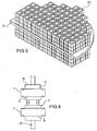
- the interior of the housing comprises an intermediate plate (9) extending in all directions to the peripheral plate (4) and dividing the interior of the housing into a lower chamber (10) and an upper chamber (11) providing respectively on the lower face (5) and the upper face (6). It still contains a network of tubes (23), better visible at the figure 3 , extending from the lower face (5) to the upper face (6), brazed to them, and crimped into the intermediate plate (9) or otherwise attached thereto.
- the tubes (23) extend in a tight network in at least most of the interior of the housing.
- the intermediate plate (9) is thinner than the peripheral face (4) and less than the lower (5) and upper (6) faces.
- the flow of the heat removal fluid in the exchanger (1) is as follows.
- the fluid enters through the inlet bore (7) in the upper chamber (11) and then infiltrates the tubes (23) by channels (12) present between them and the upper face (6), in parts not soldered at the junction. It traverses the tubes (23) through the intermediate plate (9) and leaves in the lower chamber (10) through channels (13) present between the tubes (23) and the lower face (5). It spreads into the lower chamber (10) before leaving it through the outlet bore (8). All circulating fluid therefore arrives on the lower face (5) assigned to the heat exchange and participates therein, which gives a good heat removal performance.
- the pressure loss remains moderate due to the relatively small length of the flow path, the small number of obstacles and changes of direction and the abundance of the tubes (23).
- the tubes (23) are tight and have approximately equal flow rates of fluid from the same upper chamber (11), the heat removal is approximately uniform over the entire surface of the bottom face (5). ), and the temperature is therefore almost uniform. Finally, the flexibility of the lower (5) and upper (6) faces and even of the intermediate plate (9) makes it possible to exert a continuous contact against the network (2) by a pressing originating from the upper face (6), the tubes (23) possessing however a sufficient rigidity to prevent the crushing of the exchanger (1) and to properly transmit the pressing force on a network (2).
- a plate (14) of a press pushes on the upper face (6) of the heat exchanger (1), and an opposite plate (15) of the same press pushes on the same face of the heat exchanger ( 1 '), to the network (2).
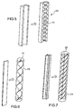
- the tubes (23) can be smooth; they may also have a special shape, for example, by providing helical grooves (20) on their inner face ( figure 5 ) or by inserting twists (21 or 22), obtained by twisting a flat or cross-shaped section ( Figures 6 and 7 ). All these elements improve the flow regularity in the tubes (23), while increasing the heat exchange area (especially the inserts), and therefore the heat removal performance.
Landscapes
- Engineering & Computer Science (AREA)
- Physics & Mathematics (AREA)
- Thermal Sciences (AREA)
- Mechanical Engineering (AREA)
- General Engineering & Computer Science (AREA)
- Cooling Or The Like Of Semiconductors Or Solid State Devices (AREA)
- Heat-Exchange Devices With Radiators And Conduit Assemblies (AREA)
Description
- Le sujet de l'invention est un échangeur de chaleur, ainsi qu'un agencement l'employant, notamment un réseau de transistors de puissance.
- Certains transistors de puissance dissipent une énergie calorifique si importante qu'un refroidissement est nécessaire. Les échangeurs de chaleur existants sont nombreux, mais leur rigidité rend souvent difficile de les appliquer avec un ajustement de contact suffisant contre un tel organe dissipateur de chaleur qui peut s'étendre sur une surface irrégulière. On doit aussi reconnaître que beaucoup n'ont pas une bonne capacité ou une bonne uniformité d'enlèvement de la chaleur sur leur surface. Enfin, certains sont sujets à des pertes de charge importantes du fluide de refroidissement.
- On citera en passant les modèles composés d'un réseau d'ailettes, généralement destinés aux refroidissements par air, sans circulation d'un fluide particulier, et qui sont insuffisants pour l'application principale envisagée. Un autre genre d'échangeurs de chaleur comprend des plaques internes en spirales imposant un écoulement en tourbillon au fluide d'échange de chaleur, l'élément à refroidir étant placé sur une face latérale du boîtier, à un bord de l'écoulement. Le brevet
EP - A - 0 613 179 décrit une telle conception, qui possède une bonne uniformité de refroidissement, mais des pertes de charge importantes et une rigidité trop grande, toutes les plaques internes s'appuyant sur l'élément à refroidir. - Une autre conception repose sur l'emploi de plaques ondulées internes délimitant des canaux de refroidissement. Dans la réalisation particulière du document
EP - A - 1 898 464 , tout en parcourant les ondulations selon leur longueur, le fluide d'échange de chaleur est amené à s'approcher de la surface d'échange de chaleur puis à s'en éloigner par des ailettes obliques : son mouvement d'ensemble est sinueux dans les canaux. Ces échangeurs ont encore, en général, une rigidité importante, l'uniformité de la température de refroidissement n'est pas très bonne, et les performances d'enlèvement de chaleur sont parfois insuffisantes. - L'invention est relative à un échangeur de chaleur perfectionné, dépourvu des inconvénients précédents et qui possède notamment une bonne souplesse lui permettant d'être appliqué sur un organe à refroidir de forme irrégulière, et en même temps une résistante suffisante pour tenir à la pression d'application souhaitée, d'excellentes performances d'enlèvement de la chaleur et d'uniformité de température, et des pertes de charge modérées pour le fluide.
- Sous une forme générale, l'invention est relative à un échangeur de chaleur comprenant : un boîtier composé d'une face inférieure, d'une face supérieure et d'une face périphérique ; un réseau de tubes parallèles s'étendant dans le boîtier de la face supérieure à la face inférieure ; une plaque intermédiaire à la face inférieure et à la face supérieure, s'étendant jusqu'à la face périphérique et divisant l'intérieur du boîtier en une chambre inférieure et une chambre supérieure ; des conduits d'entrée et de sortie de fluide de refroidissement débouchant respectivement dans la chambre supérieure et la chambre inférieure, les tubes s'étendant à travers la plaque intermédiaire et débouchant dans la chambre inférieure et la chambre supérieure.
- Elle est aussi relative à un agencement comprenant un organe dissipateur de chaleur, au moins un tel échangeur de chaleur dont la face inférieure est posée contre l'organe dissipateur de chaleur, et une presse dont un plateau presse l'organe dissipateur de chaleur vers l'échangeur de chaleur.
- L'invention sera maintenant décrite plus en détail en liaison aux figures suivantes, décrivant une réalisation purement illustrative de l'invention :
- la
figure 1 représente un agencement complet, en coupe centrale, - la
figure 2 , un échangeur de chaleur en vue de dessus, - la
figure 3 , l'intérieur d'un échangeur, - la
figure 4 , le pressage de l'agencement, - la
figure 5 , un tube particulier, - et les
figures 6 et 7 , deux réalisations d'inserts d'autres tubes particuliers. - La
figure 1 représente un agencement conforme à l'invention, avec deux échangeurs de chaleur (1 et 1') disposés de part et d'autre d'un réseau (2) plan de transistors (3) de puissance. L'agencement est à peu près symétrique, et les échangeurs de chaleur (1 et 1') peuvent être semblables. La description portera donc surtout sur l'échangeur de chaleur (1). Il comprend un boîtier composé d'une face périphérique (4) épaisse et rigide, d'une face inférieure (5) dirigée vers les transistors (3) et d'une face supérieure (6) opposée à la précédente, et plane comme elle. La face inférieure (5) sert à l'échange de chaleur, et la face supérieure (6) au pressage de l'échangeur de chaleur (1). Toutes ces faces délimitent un volume clos à l'exception d'un perçage d'entrée (7) et d'un perçage de sortie (8) opposés l'un à l'autre et représentés à lafigure 2 . La face inférieure (5) et la face supérieure (6) sont souples, c'est-à-dire aptes à se déformer pour épouser le relief de pièces pressées sur elles. - L'intérieur du boîtier comprend une plaque intermédiaire (9) s'étendant dans toutes les directions jusqu'à la plaque périphérique (4) et divisant l'intérieur du boîtier en une chambre inférieure (10) et une chambre supérieure (11) donnant respectivement sur la face inférieure (5) et la face supérieure (6). Il contient encore un réseau de tubes (23), mieux visibles à la
figure 3 , s'étendant depuis la face inférieure (5) jusqu'à la face supérieure (6), brasés à elles, et sertis dans la plaque intermédiaire (9) ou autrement fixés à elle. Les tubes (23) s'étendent en un réseau serré dans au moins la plus grande partie de l'intérieur du boîtier. La plaque intermédiaire (9) est plus fine que la face périphérique (4) et moins que les faces inférieure (5) et supérieure (6). - L'écoulement du fluide d'enlèvement de chaleur dans l'échangeur (1) est comme suit. Le fluide entre par le perçage d'entrée (7) dans la chambre supérieure (11) puis s'infiltre dans les tubes (23) par des canaux (12) présents entre eux et la face supérieure (6), dans des parties non brasées de la jonction. Il parcourt les tubes (23) à travers la plaque intermédiaire (9) et ressort dans la chambre inférieure (10) en passant par des canaux (13) présents entre les tubes (23) et la face inférieure (5). Il se répand dans la chambre inférieure (10) avant de la quitter par le perçage de sortie (8). Tout le fluide mis en circulation arrive donc sur la face inférieure (5) affectée à l'échange de chaleur et participe à celui-ci, ce qui donne une bonne performance d'enlèvement de la chaleur. La perte de charge reste modérée grâce à la longueur relativement faible du trajet d'écoulement, au petit nombre d'obstacles et de changements de direction et à l'abondance des tubes (23). Les tubes (23) étant serrés et parcourus de débits à peu près égaux d'un fluide provenant d'une même chambre supérieure (11), l'enlèvement de chaleur est à peu près uniforme sur toute la superficie de la face inférieure (5), et la température y est donc à peu près uniforme. Enfin, la souplesse des faces inférieure (5) et supérieure (6) et même de la plaque intermédiaire (9), permet d'exercer un contact continu contre le réseau (2) par un pressage originaire de la face supérieure (6), les tubes (23) possédant toutefois une rigidité suffisante pour empêcher l'écrasement de l'échangeur (1) et pour bien transmettre l'effort de pressage sur un réseau (2).
- Le pressage de l'agencement est représenté à la
figure 4 . Un plateau (14) d'une presse pousse sur la face supérieure (6) de l'échangeur de chaleur (1), et un plateau opposé (15) de la même presse pousse sur la même face de l'échangeur de chaleur (1'), vers le réseau (2). - Les tubes (23) peuvent être lisses ; ils peuvent aussi avoir une forme spéciale, par exemple, en les pourvoyant de rainures hélicoïdales (20) à leur face interne (
figure 5 ) ou en y insérant des vrilles (21 ou 22), obtenues en tordant un profilé plat ou en croisillon (figures 6 et 7 ). Tous ces éléments améliorent la régularité de l'écoulement dans les tubes (23), tout en accroissant la superficie d'échange de chaleur (surtout les inserts), et donc la performance d'enlèvement de chaleur.
Claims (4)
- Echangeur de chaleur comprenant un boîtier composé d'une face inférieure (5), d'une face supérieure (6) et d'une face périphérique (4), un réseau de tubes (23) parallèles s'étendant dans le boîtier de la face supérieure (6) à la face inférieure (5), une plaque intermédiaire (9) à la face inférieure et à la face supérieure, s'étendant jusqu'à la face périphérique et divisant l'intérieur du boîtier en une chambre inférieure (10) et une chambre supérieure (11), des conduits d'entrée (7) et de sortie (8) de liquide de refroidissement débouchant respectivement dans la chambre supérieure (11) et la chambre inférieure (10), les tubes (23) s'étendant à travers la plaque intermédiaire et débouchant par des canaux (12, 13) dans la chambre inférieure et la chambre supérieure.
- Echangeur de chaleur selon la revendication 1, caractérisé en ce que les tubes (23) sont fixés dans la plaque intermédiaire (9), sur la face inférieure (5) et la face supérieure (6), qui sont plus fines que la face périphérique (4) et la plaque intermédiaire (9).
- Echangeur de chaleur selon l'une quelconque des revendications 1 ou 2, caractérisé en ce que les tubes (23) sont pourvus de cannelures hélicoïdales (20) à leur face interne.
- Echangeur de chaleur selon l'une quelconque des revendications 1 ou 2, caractérisé en ce que les tubes (23) contiennent des inserts hélicoïdaux (21, 22).
Applications Claiming Priority (2)
| Application Number | Priority Date | Filing Date | Title |
|---|---|---|---|
| FR1050681A FR2955971B1 (fr) | 2010-02-01 | 2010-02-01 | Echangeur de chaleur notamment pour un semi-conducteur de puissance |
| PCT/EP2011/051285 WO2011092322A1 (fr) | 2010-02-01 | 2011-01-31 | Echangeur de chaleur notamment pour un semi-conducteur de puissance |
Publications (2)
| Publication Number | Publication Date |
|---|---|
| EP2532026A1 EP2532026A1 (fr) | 2012-12-12 |
| EP2532026B1 true EP2532026B1 (fr) | 2015-02-18 |
Family
ID=42635448
Family Applications (1)
| Application Number | Title | Priority Date | Filing Date |
|---|---|---|---|
| EP11701151.0A Not-in-force EP2532026B1 (fr) | 2010-02-01 | 2011-01-31 | Echangeur de chaleur notamment pour un semi-conducteur de puissance |
Country Status (5)
| Country | Link |
|---|---|
| US (1) | US20130146256A1 (fr) |
| EP (1) | EP2532026B1 (fr) |
| CA (1) | CA2788729C (fr) |
| FR (1) | FR2955971B1 (fr) |
| WO (1) | WO2011092322A1 (fr) |
Families Citing this family (1)
| Publication number | Priority date | Publication date | Assignee | Title |
|---|---|---|---|---|
| US11573053B2 (en) * | 2019-08-13 | 2023-02-07 | General Electric Company | Cyclone cooler device |
Family Cites Families (13)
| Publication number | Priority date | Publication date | Assignee | Title |
|---|---|---|---|---|
| US206998A (en) * | 1878-08-13 | Improvement in steam-generators | ||
| US4072188A (en) * | 1975-07-02 | 1978-02-07 | Honeywell Information Systems Inc. | Fluid cooling systems for electronic systems |
| JPS5928839B2 (ja) * | 1980-09-01 | 1984-07-16 | 工業技術院長 | 蓄熱機能を有する熱サイフオン型ヒ−トパイプ |
| US4882654A (en) * | 1988-12-22 | 1989-11-21 | Microelectronics And Computer Technology Corporation | Method and apparatus for adjustably mounting a heat exchanger for an electronic component |
| JPH05136305A (ja) * | 1991-11-08 | 1993-06-01 | Hitachi Ltd | 発熱体の冷却装置 |
| JP2745948B2 (ja) * | 1992-04-06 | 1998-04-28 | 日本電気株式会社 | 集積回路の冷却構造 |
| US5406807A (en) * | 1992-06-17 | 1995-04-18 | Hitachi, Ltd. | Apparatus for cooling semiconductor device and computer having the same |
| GB9303940D0 (en) * | 1993-02-26 | 1993-04-14 | Gec Alsthom Ltd | Heat sink |
| US20030111209A1 (en) * | 1999-01-20 | 2003-06-19 | Hino Motors, Ltd. | EGR cooler |
| JP4822238B2 (ja) * | 2001-07-24 | 2011-11-24 | 株式会社日本製鋼所 | 液媒用内面溝付伝熱管とその伝熱管を用いた熱交換器 |
| JP4881583B2 (ja) | 2005-06-27 | 2012-02-22 | 株式会社豊田自動織機 | パワーモジュール用ヒートシンク |
| US7849914B2 (en) * | 2006-05-02 | 2010-12-14 | Clockspeed, Inc. | Cooling apparatus for microelectronic devices |
| US7884468B2 (en) * | 2007-07-30 | 2011-02-08 | GM Global Technology Operations LLC | Cooling systems for power semiconductor devices |
-
2010
- 2010-02-01 FR FR1050681A patent/FR2955971B1/fr not_active Expired - Fee Related
-
2011
- 2011-01-31 WO PCT/EP2011/051285 patent/WO2011092322A1/fr not_active Ceased
- 2011-01-31 CA CA2788729A patent/CA2788729C/fr not_active Expired - Fee Related
- 2011-01-31 US US13/576,501 patent/US20130146256A1/en not_active Abandoned
- 2011-01-31 EP EP11701151.0A patent/EP2532026B1/fr not_active Not-in-force
Also Published As
| Publication number | Publication date |
|---|---|
| CA2788729C (fr) | 2017-09-26 |
| CA2788729A1 (fr) | 2011-08-04 |
| FR2955971B1 (fr) | 2012-03-09 |
| US20130146256A1 (en) | 2013-06-13 |
| FR2955971A1 (fr) | 2011-08-05 |
| EP2532026A1 (fr) | 2012-12-12 |
| WO2011092322A1 (fr) | 2011-08-04 |
Similar Documents
| Publication | Publication Date | Title |
|---|---|---|
| US10006722B2 (en) | Structural support element in heat exchangers | |
| EP2770809B1 (fr) | Carte électronique | |
| FR2902507A1 (fr) | Echangeur de chaleur | |
| CN108847511A (zh) | 一种基于电池模组的一体化换热结构 | |
| EP3931507A1 (fr) | Dispositif de regulation thermique, notamment de refroidissement pour vehicule automobile | |
| WO2018109368A1 (fr) | Echangeur de chaleur à plaques, dispositif de stockage d'énergie et leur procédé de fabrication | |
| EP0680585A1 (fr) | Chaudiere electrique pour liquide caloporteur en circulation dans un circuit ouvert ou ferme | |
| CN104236348B (zh) | 一种换热器 | |
| WO2020212457A1 (fr) | Dispositif de régulation thermique, notamment de refroidissement pour véhicule automobile | |
| EP2532026B1 (fr) | Echangeur de chaleur notamment pour un semi-conducteur de puissance | |
| EP4086556A1 (fr) | Module d'échangeur de chaleur à plaques à canaux intégrant au moins une zone d'alimentation et de distribution de fluide formée par des plots | |
| FR2997485A1 (fr) | Echangeur thermique, notamment pour vehicule automobile | |
| WO2020053506A1 (fr) | Dispositif de regulation thermique, notamment de refroidissement | |
| FR3068773B1 (fr) | Dispositif de regulation thermique de modules de batterie | |
| EP3099994B1 (fr) | Echangeur de chaleur pour véhicule automobile | |
| EP3452772B1 (fr) | Echangeur thermique en matière plastique et véhicule comprenant cet échangeur | |
| CN103097847B (zh) | 热交换器 | |
| WO2020043960A1 (fr) | Dispositif de régulation thermique, notamment de refroidissement | |
| EP2487443A1 (fr) | Condenseur pour échange thermique optimisé et installation de chauffage de liquides le comportant | |
| FR2806468A3 (fr) | Ensemble formant matrice pour souder un tube de transfert de chaleur semblable a un panneau a un dissipateur de chaleur | |
| CN100398971C (zh) | 超细管道热交换器 | |
| EP4521052A1 (fr) | Echangeur de chaleur à plaques pour la séparation de phases | |
| FR3096767A1 (fr) | Échangeur thermique a déflection | |
| EP2936574A1 (fr) | Générateur thermo électrique | |
| BE702095A (fr) |
Legal Events
| Date | Code | Title | Description |
|---|---|---|---|
| PUAI | Public reference made under article 153(3) epc to a published international application that has entered the european phase |
Free format text: ORIGINAL CODE: 0009012 |
|
| 17P | Request for examination filed |
Effective date: 20120730 |
|
| AK | Designated contracting states |
Kind code of ref document: A1 Designated state(s): AL AT BE BG CH CY CZ DE DK EE ES FI FR GB GR HR HU IE IS IT LI LT LU LV MC MK MT NL NO PL PT RO RS SE SI SK SM TR |
|
| DAX | Request for extension of the european patent (deleted) | ||
| REG | Reference to a national code |
Ref country code: DE Ref legal event code: R079 Ref document number: 602011013760 Country of ref document: DE Free format text: PREVIOUS MAIN CLASS: H01L0023473000 Ipc: F28D0015000000 |
|
| RIC1 | Information provided on ipc code assigned before grant |
Ipc: F28D 15/00 20060101AFI20130903BHEP Ipc: H01L 23/473 20060101ALI20130903BHEP |
|
| GRAP | Despatch of communication of intention to grant a patent |
Free format text: ORIGINAL CODE: EPIDOSNIGR1 |
|
| INTG | Intention to grant announced |
Effective date: 20131021 |
|
| GRAP | Despatch of communication of intention to grant a patent |
Free format text: ORIGINAL CODE: EPIDOSNIGR1 |
|
| INTG | Intention to grant announced |
Effective date: 20140826 |
|
| GRAS | Grant fee paid |
Free format text: ORIGINAL CODE: EPIDOSNIGR3 |
|
| GRAA | (expected) grant |
Free format text: ORIGINAL CODE: 0009210 |
|
| AK | Designated contracting states |
Kind code of ref document: B1 Designated state(s): AL AT BE BG CH CY CZ DE DK EE ES FI FR GB GR HR HU IE IS IT LI LT LU LV MC MK MT NL NO PL PT RO RS SE SI SK SM TR |
|
| REG | Reference to a national code |
Ref country code: GB Ref legal event code: FG4D Free format text: NOT ENGLISH |
|
| REG | Reference to a national code |
Ref country code: CH Ref legal event code: NV Representative=s name: BOVARD AG, CH Ref country code: CH Ref legal event code: EP |
|
| REG | Reference to a national code |
Ref country code: AT Ref legal event code: REF Ref document number: 710830 Country of ref document: AT Kind code of ref document: T Effective date: 20150315 |
|
| REG | Reference to a national code |
Ref country code: IE Ref legal event code: FG4D Free format text: LANGUAGE OF EP DOCUMENT: FRENCH |
|
| REG | Reference to a national code |
Ref country code: DE Ref legal event code: R096 Ref document number: 602011013760 Country of ref document: DE Effective date: 20150402 |
|
| REG | Reference to a national code |
Ref country code: SE Ref legal event code: TRGR |
|
| REG | Reference to a national code |
Ref country code: NL Ref legal event code: VDEP Effective date: 20150218 |
|
| REG | Reference to a national code |
Ref country code: AT Ref legal event code: MK05 Ref document number: 710830 Country of ref document: AT Kind code of ref document: T Effective date: 20150218 |
|
| REG | Reference to a national code |
Ref country code: LT Ref legal event code: MG4D |
|
| PG25 | Lapsed in a contracting state [announced via postgrant information from national office to epo] |
Ref country code: ES Free format text: LAPSE BECAUSE OF FAILURE TO SUBMIT A TRANSLATION OF THE DESCRIPTION OR TO PAY THE FEE WITHIN THE PRESCRIBED TIME-LIMIT Effective date: 20150218 Ref country code: LT Free format text: LAPSE BECAUSE OF FAILURE TO SUBMIT A TRANSLATION OF THE DESCRIPTION OR TO PAY THE FEE WITHIN THE PRESCRIBED TIME-LIMIT Effective date: 20150218 Ref country code: NO Free format text: LAPSE BECAUSE OF FAILURE TO SUBMIT A TRANSLATION OF THE DESCRIPTION OR TO PAY THE FEE WITHIN THE PRESCRIBED TIME-LIMIT Effective date: 20150518 Ref country code: HR Free format text: LAPSE BECAUSE OF FAILURE TO SUBMIT A TRANSLATION OF THE DESCRIPTION OR TO PAY THE FEE WITHIN THE PRESCRIBED TIME-LIMIT Effective date: 20150218 |
|
| PG25 | Lapsed in a contracting state [announced via postgrant information from national office to epo] |
Ref country code: NL Free format text: LAPSE BECAUSE OF FAILURE TO SUBMIT A TRANSLATION OF THE DESCRIPTION OR TO PAY THE FEE WITHIN THE PRESCRIBED TIME-LIMIT Effective date: 20150218 Ref country code: LV Free format text: LAPSE BECAUSE OF FAILURE TO SUBMIT A TRANSLATION OF THE DESCRIPTION OR TO PAY THE FEE WITHIN THE PRESCRIBED TIME-LIMIT Effective date: 20150218 Ref country code: IS Free format text: LAPSE BECAUSE OF FAILURE TO SUBMIT A TRANSLATION OF THE DESCRIPTION OR TO PAY THE FEE WITHIN THE PRESCRIBED TIME-LIMIT Effective date: 20150618 Ref country code: AT Free format text: LAPSE BECAUSE OF FAILURE TO SUBMIT A TRANSLATION OF THE DESCRIPTION OR TO PAY THE FEE WITHIN THE PRESCRIBED TIME-LIMIT Effective date: 20150218 Ref country code: RS Free format text: LAPSE BECAUSE OF FAILURE TO SUBMIT A TRANSLATION OF THE DESCRIPTION OR TO PAY THE FEE WITHIN THE PRESCRIBED TIME-LIMIT Effective date: 20150218 Ref country code: GR Free format text: LAPSE BECAUSE OF FAILURE TO SUBMIT A TRANSLATION OF THE DESCRIPTION OR TO PAY THE FEE WITHIN THE PRESCRIBED TIME-LIMIT Effective date: 20150519 |
|
| PG25 | Lapsed in a contracting state [announced via postgrant information from national office to epo] |
Ref country code: DK Free format text: LAPSE BECAUSE OF FAILURE TO SUBMIT A TRANSLATION OF THE DESCRIPTION OR TO PAY THE FEE WITHIN THE PRESCRIBED TIME-LIMIT Effective date: 20150218 Ref country code: EE Free format text: LAPSE BECAUSE OF FAILURE TO SUBMIT A TRANSLATION OF THE DESCRIPTION OR TO PAY THE FEE WITHIN THE PRESCRIBED TIME-LIMIT Effective date: 20150218 Ref country code: CZ Free format text: LAPSE BECAUSE OF FAILURE TO SUBMIT A TRANSLATION OF THE DESCRIPTION OR TO PAY THE FEE WITHIN THE PRESCRIBED TIME-LIMIT Effective date: 20150218 Ref country code: SK Free format text: LAPSE BECAUSE OF FAILURE TO SUBMIT A TRANSLATION OF THE DESCRIPTION OR TO PAY THE FEE WITHIN THE PRESCRIBED TIME-LIMIT Effective date: 20150218 Ref country code: RO Free format text: LAPSE BECAUSE OF FAILURE TO SUBMIT A TRANSLATION OF THE DESCRIPTION OR TO PAY THE FEE WITHIN THE PRESCRIBED TIME-LIMIT Effective date: 20150218 |
|
| REG | Reference to a national code |
Ref country code: DE Ref legal event code: R097 Ref document number: 602011013760 Country of ref document: DE |
|
| PG25 | Lapsed in a contracting state [announced via postgrant information from national office to epo] |
Ref country code: PL Free format text: LAPSE BECAUSE OF FAILURE TO SUBMIT A TRANSLATION OF THE DESCRIPTION OR TO PAY THE FEE WITHIN THE PRESCRIBED TIME-LIMIT Effective date: 20150218 |
|
| PLBE | No opposition filed within time limit |
Free format text: ORIGINAL CODE: 0009261 |
|
| STAA | Information on the status of an ep patent application or granted ep patent |
Free format text: STATUS: NO OPPOSITION FILED WITHIN TIME LIMIT |
|
| PG25 | Lapsed in a contracting state [announced via postgrant information from national office to epo] |
Ref country code: IT Free format text: LAPSE BECAUSE OF FAILURE TO SUBMIT A TRANSLATION OF THE DESCRIPTION OR TO PAY THE FEE WITHIN THE PRESCRIBED TIME-LIMIT Effective date: 20150218 |
|
| 26N | No opposition filed |
Effective date: 20151119 |
|
| REG | Reference to a national code |
Ref country code: FR Ref legal event code: PLFP Year of fee payment: 6 |
|
| PG25 | Lapsed in a contracting state [announced via postgrant information from national office to epo] |
Ref country code: SI Free format text: LAPSE BECAUSE OF FAILURE TO SUBMIT A TRANSLATION OF THE DESCRIPTION OR TO PAY THE FEE WITHIN THE PRESCRIBED TIME-LIMIT Effective date: 20150218 |
|
| PG25 | Lapsed in a contracting state [announced via postgrant information from national office to epo] |
Ref country code: BE Free format text: LAPSE BECAUSE OF NON-PAYMENT OF DUE FEES Effective date: 20160131 |
|
| PG25 | Lapsed in a contracting state [announced via postgrant information from national office to epo] |
Ref country code: LU Free format text: LAPSE BECAUSE OF FAILURE TO SUBMIT A TRANSLATION OF THE DESCRIPTION OR TO PAY THE FEE WITHIN THE PRESCRIBED TIME-LIMIT Effective date: 20160131 |
|
| PG25 | Lapsed in a contracting state [announced via postgrant information from national office to epo] |
Ref country code: MC Free format text: LAPSE BECAUSE OF FAILURE TO SUBMIT A TRANSLATION OF THE DESCRIPTION OR TO PAY THE FEE WITHIN THE PRESCRIBED TIME-LIMIT Effective date: 20150218 |
|
| REG | Reference to a national code |
Ref country code: IE Ref legal event code: MM4A |
|
| REG | Reference to a national code |
Ref country code: FR Ref legal event code: PLFP Year of fee payment: 7 |
|
| PG25 | Lapsed in a contracting state [announced via postgrant information from national office to epo] |
Ref country code: IE Free format text: LAPSE BECAUSE OF NON-PAYMENT OF DUE FEES Effective date: 20160131 |
|
| PG25 | Lapsed in a contracting state [announced via postgrant information from national office to epo] |
Ref country code: MT Free format text: LAPSE BECAUSE OF FAILURE TO SUBMIT A TRANSLATION OF THE DESCRIPTION OR TO PAY THE FEE WITHIN THE PRESCRIBED TIME-LIMIT Effective date: 20150218 |
|
| REG | Reference to a national code |
Ref country code: FR Ref legal event code: PLFP Year of fee payment: 8 |
|
| PGFP | Annual fee paid to national office [announced via postgrant information from national office to epo] |
Ref country code: FI Payment date: 20180129 Year of fee payment: 8 Ref country code: CH Payment date: 20180127 Year of fee payment: 8 Ref country code: GB Payment date: 20180129 Year of fee payment: 8 Ref country code: DE Payment date: 20180129 Year of fee payment: 8 |
|
| PG25 | Lapsed in a contracting state [announced via postgrant information from national office to epo] |
Ref country code: SM Free format text: LAPSE BECAUSE OF FAILURE TO SUBMIT A TRANSLATION OF THE DESCRIPTION OR TO PAY THE FEE WITHIN THE PRESCRIBED TIME-LIMIT Effective date: 20150218 Ref country code: HU Free format text: LAPSE BECAUSE OF FAILURE TO SUBMIT A TRANSLATION OF THE DESCRIPTION OR TO PAY THE FEE WITHIN THE PRESCRIBED TIME-LIMIT; INVALID AB INITIO Effective date: 20110131 Ref country code: CY Free format text: LAPSE BECAUSE OF FAILURE TO SUBMIT A TRANSLATION OF THE DESCRIPTION OR TO PAY THE FEE WITHIN THE PRESCRIBED TIME-LIMIT Effective date: 20150218 |
|
| PGFP | Annual fee paid to national office [announced via postgrant information from national office to epo] |
Ref country code: SE Payment date: 20180129 Year of fee payment: 8 Ref country code: FR Payment date: 20180125 Year of fee payment: 8 |
|
| PG25 | Lapsed in a contracting state [announced via postgrant information from national office to epo] |
Ref country code: PT Free format text: LAPSE BECAUSE OF FAILURE TO SUBMIT A TRANSLATION OF THE DESCRIPTION OR TO PAY THE FEE WITHIN THE PRESCRIBED TIME-LIMIT Effective date: 20150218 Ref country code: MK Free format text: LAPSE BECAUSE OF FAILURE TO SUBMIT A TRANSLATION OF THE DESCRIPTION OR TO PAY THE FEE WITHIN THE PRESCRIBED TIME-LIMIT Effective date: 20150218 Ref country code: TR Free format text: LAPSE BECAUSE OF FAILURE TO SUBMIT A TRANSLATION OF THE DESCRIPTION OR TO PAY THE FEE WITHIN THE PRESCRIBED TIME-LIMIT Effective date: 20150218 |
|
| PG25 | Lapsed in a contracting state [announced via postgrant information from national office to epo] |
Ref country code: BG Free format text: LAPSE BECAUSE OF FAILURE TO SUBMIT A TRANSLATION OF THE DESCRIPTION OR TO PAY THE FEE WITHIN THE PRESCRIBED TIME-LIMIT Effective date: 20150218 |
|
| PG25 | Lapsed in a contracting state [announced via postgrant information from national office to epo] |
Ref country code: AL Free format text: LAPSE BECAUSE OF FAILURE TO SUBMIT A TRANSLATION OF THE DESCRIPTION OR TO PAY THE FEE WITHIN THE PRESCRIBED TIME-LIMIT Effective date: 20150218 |
|
| REG | Reference to a national code |
Ref country code: DE Ref legal event code: R119 Ref document number: 602011013760 Country of ref document: DE |
|
| REG | Reference to a national code |
Ref country code: CH Ref legal event code: PL |
|
| GBPC | Gb: european patent ceased through non-payment of renewal fee |
Effective date: 20190131 |
|
| REG | Reference to a national code |
Ref country code: SE Ref legal event code: EUG |
|
| PG25 | Lapsed in a contracting state [announced via postgrant information from national office to epo] |
Ref country code: DE Free format text: LAPSE BECAUSE OF NON-PAYMENT OF DUE FEES Effective date: 20190801 Ref country code: FR Free format text: LAPSE BECAUSE OF NON-PAYMENT OF DUE FEES Effective date: 20190131 Ref country code: FI Free format text: LAPSE BECAUSE OF NON-PAYMENT OF DUE FEES Effective date: 20190131 Ref country code: SE Free format text: LAPSE BECAUSE OF NON-PAYMENT OF DUE FEES Effective date: 20190201 |
|
| PG25 | Lapsed in a contracting state [announced via postgrant information from national office to epo] |
Ref country code: LI Free format text: LAPSE BECAUSE OF NON-PAYMENT OF DUE FEES Effective date: 20190131 Ref country code: CH Free format text: LAPSE BECAUSE OF NON-PAYMENT OF DUE FEES Effective date: 20190131 Ref country code: GB Free format text: LAPSE BECAUSE OF NON-PAYMENT OF DUE FEES Effective date: 20190131 |