EP2532050B1 - Antenne plane directive embarquée, véhicule comportant une telle antenne et système de télécommunication par satellite comportant un tel véhicule - Google Patents
Antenne plane directive embarquée, véhicule comportant une telle antenne et système de télécommunication par satellite comportant un tel véhicule Download PDFInfo
- Publication number
- EP2532050B1 EP2532050B1 EP11700955.5A EP11700955A EP2532050B1 EP 2532050 B1 EP2532050 B1 EP 2532050B1 EP 11700955 A EP11700955 A EP 11700955A EP 2532050 B1 EP2532050 B1 EP 2532050B1
- Authority
- EP
- European Patent Office
- Prior art keywords
- waveguides
- radiating
- antenna
- phase
- antenna according
- Prior art date
- Legal status (The legal status is an assumption and is not a legal conclusion. Google has not performed a legal analysis and makes no representation as to the accuracy of the status listed.)
- Not-in-force
Links
Images


Classifications
-
- H—ELECTRICITY
- H01—ELECTRIC ELEMENTS
- H01Q—ANTENNAS, i.e. RADIO AERIALS
- H01Q21/00—Antenna arrays or systems
- H01Q21/24—Combinations of antenna units polarised in different directions for transmitting or receiving circularly and elliptically polarised waves or waves linearly polarised in any direction
-
- H—ELECTRICITY
- H01—ELECTRIC ELEMENTS
- H01Q—ANTENNAS, i.e. RADIO AERIALS
- H01Q21/00—Antenna arrays or systems
- H01Q21/0006—Particular feeding systems
- H01Q21/0037—Particular feeding systems linear waveguide fed arrays
- H01Q21/0043—Slotted waveguides
-
- H—ELECTRICITY
- H01—ELECTRIC ELEMENTS
- H01Q—ANTENNAS, i.e. RADIO AERIALS
- H01Q21/00—Antenna arrays or systems
- H01Q21/0006—Particular feeding systems
- H01Q21/0037—Particular feeding systems linear waveguide fed arrays
- H01Q21/0043—Slotted waveguides
- H01Q21/005—Slotted waveguides arrays
-
- H—ELECTRICITY
- H04—ELECTRIC COMMUNICATION TECHNIQUE
- H04B—TRANSMISSION
- H04B7/00—Radio transmission systems, i.e. using radiation field
- H04B7/14—Relay systems
- H04B7/15—Active relay systems
- H04B7/185—Space-based or airborne stations; Stations for satellite systems
- H04B7/18502—Airborne stations
- H04B7/18506—Communications with or from aircraft, i.e. aeronautical mobile service
- H04B7/18508—Communications with or from aircraft, i.e. aeronautical mobile service with satellite system used as relay, i.e. aeronautical mobile satellite service
Definitions
- the present invention relates to an on-board directive planar antenna, a vehicle comprising such an antenna and a satellite telecommunications system comprising such a vehicle. It applies in particular to the field of satellite telecommunications and more particularly to telecommunications equipment installed on mobile vehicles such as land, sea or aeronautical means of transport to ensure a bi-directional Ka-band connection between a mobile terminal and a earth station via a repeater installed on a satellite. According to a particular embodiment, it also applies to the simultaneous tracking of two separate satellites operating in Ka band and L band respectively.
- Satellite transmissions can be masked by obstacles in the pointing direction of a satellite. Obstacles can be vegetation or infrastructure such as buildings or bridges. It is therefore necessary, to increase the availability of the radio frequency link with a satellite, to have a spatial diversity allowing the tracking of two satellites simultaneously.
- the two satellites having different pointing directions, the simultaneous tracking of two satellites requires a bi-beam antenna with independent pointing, such as an antenna with electronic scanning, or two antennas with mechanical pointing.
- the antenna In the case of an electronic scanning antenna, to cover a territory such as Europe, the antenna must be able to ensure, in transmission and reception, pointing in an angular range between 0 ° and 360 ° in azimuth and between 20 ° and 60 ° on average in elevation.
- each antenna When using a double antenna with mechanical pointing, each antenna generates a beam using an independent mechanical pointing system to point the two satellites simultaneously.
- the pointing of each antenna towards a satellite is carried out by a combination of two mechanical movements.
- a first mechanical movement is obtained by means of a rotating platform arranged in an XY plane and ensuring the orientation of the antenna in azimuth.
- a second movement in elevation is carried out by an annex device, for example a plane mirror, integral with the platform.
- Each antenna conventionally comprises a parabolic reflector and a radiating source illuminating the reflector. To reduce the size of the reflector and reduce the height of the antenna, its periphery is elliptical instead of circular.
- such a simple antenna currently deployed on high-speed trains has a height of the order of 45 cm. Although this height is compatible with current trains, it is too important for future high-speed trains with two bridges for which the height available for the installation of an antenna, between the roof of the train and the overhead lines, is much lower.
- the height of the antenna has an influence on the drag generated by the aircraft as well as on the fuel consumption.
- the current reflector antennas installed on airplanes have a height of the order of 30 cm and cause overconsumption of fuel equivalent to eight additional passengers.
- the antenna is composed of two parallel plates between which circulate longitudinal current components and an array of one dimension of continuous transverse grooves which couple and radiate energy in space.
- the two plates and the network of grooves are mounted on two coplanar plates mechanically rotating independently of one another, the two rotational movements being superimposed and produced in the same plane of the plates.
- the orientation of the lower plate makes it possible to adjust the pointing direction in azimuth
- the orientation of the upper plate makes it possible to obtain a variable inclination of the grooves and thus to modify the pointing direction in elevation of the beam generated by the antenna.
- this antenna initially operating in linear polarization, it is necessary to add an additional orientable polarization grid mounted on the upper face of the antenna to control the plane of polarization of the antenna which increases the complexity of implementation. and the height of the antenna which is then not flat.
- the antenna comprises several alternating planes of substrates and metal planes superimposed one above the other.
- the antenna comprises a first lower metallic plane, then a first substrate plane comprising several sources, the first substrate plane comprising a lateral end forming a parabolic surface on which the waves emitted by the sources are reflected.
- Above the first substrate plane is a second metallic plane having slots for coupling the reflected wave plane, each coupling slot opening out into respective slot waveguides arranged side by side. parallel to each other in the same second substrate plane.
- the guided waves are then emitted in the form of a beam radiated through a plurality of radiating openings formed in a third upper metallic plane.
- This antenna is very elliptical, the dimension of the mirror in its region articulated on the platform being much greater than the dimension of the mirror in its region inclined above the platform, which makes it possible to reduce the height of the antenna to 20 or 30cm, but this height is still too large for an application to means of transport.
- a first object of the invention is to provide a planar on-board directive antenna which does not have the drawbacks of existing antennas and which can be installed on a mobile means of transport.
- the object of the invention is to provide a planar on-board directive antenna, operating in Ka band, very compact in the direction of its height, simple to implement and low cost, capable of remaining pointed. on a continuous satellite whatever the position of the means of transport and allowing control of the plane of polarization without adding an orientable grid.
- a second object of the invention is to produce a very compact on-board hybrid planar antenna operating in Ka band and L band, allowing the simultaneous tracking of two satellites.
- the invention relates to an on-board directive planar antenna as defined in claim 1.
- each rafter forms an angle equal to 90 °.
- the network of guides with radiating slots is mounted on a rotating platform in azimuth.
- the external electronic phase shift circuit comprising a first external phase shifter having an equal phase value at 180 ° intended to supply two waveguides in phase opposition, the other two waveguides being supplied in phase, and a second external phase shifter having a phase value equal to 90 ° intended to establish a phase quadrature between the two waveguides supplied in phase and the two waveguides supplied in phase opposition.
- the planar antenna comprises two networks of waveguides with radiating slits, of identical structure, dedicated respectively to transmission and to reception.
- the planar antenna further comprises a plurality of radiating dipoles in L-band, the radiating dipoles being located on one of the metal plates of the waveguide networks with radiating slots mounted on the rotating platform.
- the invention also relates to a vehicle comprising at least one such flat antenna and a satellite telecommunications system comprising at least one such vehicle.
- the planar antenna partially shown on the Figures 1a and 1b is of tri-plate structure. It comprises a network 5 of radiating slit waveguides comprising an alternating succession of three metal plates M1, M2, M3 respectively lower, intermediate and upper, superposed parallel to one another, and two dielectric substrates Sub1, Sub2 , respectively lower and upper, interposed between two consecutive metal plates.
- the planes of the different layers of the antenna are parallel to an XY plane.
- the height of the antenna is along an axis Z orthogonal to the XY plane.
- the upper dielectric substrate Sub2 supports the waveguides with radiating slits 10, the lower substrate Sub1 supports waveguides 11 intended to supply each waveguide with radiating slits 10 by a microwave signal.
- the network 5 comprises at least four waveguides with radiating slits arranged in the upper substrate and four corresponding feed waveguides arranged in the lower substrate.
- the radiating slit waveguides 10 of the upper substrate and the waveguides 11 of the lower substrate are identical, correspond in pairs and communicate with each other in pairs by means of coupling slots 13 passing through the M2 intermediate metal plate.
- each waveguide 11 of the lower substrate Sub1 comprises two metal walls, lower and upper, respectively formed by the lower metal plates M1 and intermediate M2 and lateral metal walls connecting the two lower metal plates M1 and intermediate M2.
- Each waveguide 11 of the lower substrate Sub1 further comprises a coupling slot 13 passing through the intermediate metal plate M2 and opening into a waveguide 10 of the upper substrate Sub2.
- Each waveguide 10 of the upper substrate Sub2 has two metal walls, lower and upper, respectively formed by the intermediate metal plates M2 and upper M3 and lateral metal walls connecting the two intermediate metal plates M2 and upper M3.
- the waveguides 10, 11 extend along a longitudinal axis parallel to the same direction, which may correspond, for example, to the axis X and have two opposite ends 15, 16 on this axis.
- the waveguides of the upper substrate Sub2 are closed at their two ends 15, 16 by first and second transverse metal walls 17, 18 connecting the three metal plates M1, M2, M3 together while the waveguides of the lower substrate are closed at only one end 16 by the first transverse wall 17, their open end 15 corresponding to a signal input 19.
- Each waveguide 10 of the upper substrate Sub2 further comprises a plurality of radiating slots 20 passing through the upper metal plate M3.
- All the radiating slots 20 arranged in the same waveguide are mutually parallel and oriented in the same direction, for example at 45 ° with respect to the directions X and Y and emit a polarized wave plane parallel to their orientation.
- the radiating slots 20 of two adjacent waveguides 10 are arranged in chevrons, each chevron forming a non-zero angle, for example equal to 90 °.
- all the slits are oriented at 45 ° relative to the X and Y directions but the radiating slits 20 of two adjacent waveguides are arranged in chevrons and form an angle of 90 ° therebetween.
- Each waveguide 11 of the lower substrate Sub1 comprises an internal individual supply circuit 25 capable of receiving an incoming microwave signal 19 applied to its open end, this internal individual supply circuit 25 comprising an internal individual electronic phase shift circuit and amplification comprising an internal phase shifter 21 for controlling the phase of the signal to be transmitted and an internal amplification device 22 of the incoming signal making it possible to control the radiation emitted by the antenna.
- the incoming signal 19 can be emitted for example by an external source 24, for example unique, then divided by a divider 26 connected at the input of each of the waveguides 11 of the lower substrate Sub1.
- the incoming signal 19 in one of the waveguides 11 of the lower substrate Sub1 is transmitted in a corresponding waveguide 10 of the upper substrate Sub2 via the coupling slots 13 in the intermediate metal plate M2 then radiated by the radiating slots 20 A sweep and a deflection of the beam in elevation, in a plane ZX perpendicular to the plane XY of the antenna, is obtained by controlling the law of phase and amplitude applied electronically by the internal internal supply circuits of each guide.
- wave 11 of the lower substrate corresponding to each of the waveguides 10 with radiating slits.
- Each waveguide 11 of the lower substrate Sub1 being supplied individually by an internal circuit 25 and comprising an individual internal electronic phase shift 21 and amplification 22 circuit, the phase control is carried out continuously which makes it possible to continuously control the direction of radiation of the antenna in elevation. Furthermore, the amplification is distributed in each waveguide 11 which allows the use of low power amplifiers and to overcome a complex and bulky external amplification circuit. In addition, no high energy source switching means is required to achieve continuous scanning of the beam.
- the network 5 of radiating slit waveguides further comprises a second external electronic phase shift circuit placed at the input of the network 5, this second phase shift circuit comprising a first external phase shifter 23 having a phase value equal to 180 ° intended to supply the second waveguide with radiating slits in phase opposition with respect to the first waveguide with radiating slits and a second external phase shifter 27 having a phase value equal to 90 ° intended to establish a phase quadrature between the signals feeding the first two waveguides 11 and the signals feeding the third and fourth waveguides 11.
- the first and second waveguides being supplied in opposition to phase, the waves they emit combine vectorially with each other and radiate globally a resultant wave polarized in the X direction, the polarization components in the Y direction canceling each other out.
- the third and fourth waveguides being supplied in phase, the waves which they emit combine vectorially with one another and generally radiate a resultant wave polarized in the direction Y, the components of polarization in the direction X canceling each other out.
- the two resulting waves polarized respectively in the directions X and Y and supplied in phase quadrature then combine with one another in a global wave circularly polarized and emitted by the network of radiating slit waveguides 5.
- the pointing of the beam in azimuth is achieved by rotation of the platform and the pointing of the beam in elevation is given by the phase law applied to the incoming signals 19
- This phase law is obtained by controlling the internal phase shifters 21 and the internal amplifiers 22 integrated in each of the waveguides 11 of the lower substrate Sub1.
- the waveguides 10 with radiating slits operating in a low bandwidth it is possible to split the transmission and reception functions and to use as shown in the figure 2 , a system of planar antennas 6, 8 comprising a first array of slot wave guides dedicated to transmission and a second array of slot wave guides, not shown, dedicated to reception, the two array of slotted waveguides having an identical structure and mounted on the same platform 7 rotating in azimuth.
- the pointing in elevation of each of the transmitting and receiving antennas of the planar antenna system mounted on the rotating platform is achieved by amplification and electronic control of the phases of each of the signals flowing in the slot guides forming the arrays of radiation from the two antennas.
- the height of the antenna without the rotating platform on which it is mounted is a few millimeters.
- the total height of the antenna with the rotating platform 7 is almost equal to the height of the rotating platform, ie of the order of 2 to 3 cm.
- the planar antenna thus produced radiates a circularly polarized wave which meets the height conditions imposed for installation on a means of transport and in particular on a future high-speed train.
- the electronic control of the phases and amplitudes of the signals feeding this antenna comprises a number of active elements, typically less than 50, limited elements.
- the desired coverage area is very large and the aircraft is liable to evolve in areas where the Ka-band satellite is no longer visible but where a Ku-band satellite is accessible.
- Ku-band antennas must operate in linear polarization. Linear polarization is obtained by orienting all the radiating slits of all the waveguides of the upper substrate in the same direction.
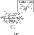
- FIG 4 A very compact on-board hybrid antenna system operating in Ka (and / or Ku) and L-band is shown, allowing the simultaneous tracking of two satellites.
- the L-band antenna is installed on the same rotating platform 7 in azimuth as the Ka and / or Ku antenna.
- the L-band antenna has a plurality of crossed dipoles 40 radiating oriented in two orthogonal directions, each radiating dipole comprising two metal appendages 41, 42 located on one of the upper metal plates M3, intermediate M2 or lower M1 of the antenna operating in Ka band and / or the antenna operating in Ku band.
- These appendages 41, 42 are dimensioned to operate in L-band and therefore do not disturb the Ka or Ku antennas on which they are installed.
- the crossed dipoles are individually controlled in phase by a phase shifter not shown, and radiate according to a phase law which their own while following the azimuth orientation of the platform 7 and imposed by the satellite pointed by the antenna Ka and / or Ku.
- the phase law of the dipoles 41, 42 of the L-band antenna is electronically controlled so as to continuously point a satellite operating in L-band.
- the antenna thus produced is very compact and allows the simultaneous tracking of two satellites operating respectively in Ka-band and L-band or Ku-band and L-band thanks to its operation in Ka-band and Ka-band or in Ka-band, Ku-band and L-band depending on the type of guide networks with radiating slits which are installed on the azimuth platform and the linear and / or circular polarization generated by the phase law combined with the orientation of the radiating slits of these networks.
Landscapes
- Engineering & Computer Science (AREA)
- Physics & Mathematics (AREA)
- Astronomy & Astrophysics (AREA)
- Aviation & Aerospace Engineering (AREA)
- General Physics & Mathematics (AREA)
- Computer Networks & Wireless Communication (AREA)
- Signal Processing (AREA)
- Variable-Direction Aerials And Aerial Arrays (AREA)
- Waveguide Aerials (AREA)
Description
- La présente invention concerne une antenne plane directive embarquée, un véhicule comportant une telle antenne et un système de télécommunication par satellite comportant un tel véhicule. Elle s'applique notamment au domaine des télécommunications par satellite et plus particulièrement aux équipements de télécommunication implantés sur des véhicules mobiles tels que des moyens de transport terrestres, maritimes ou aéronautiques pour assurer une connexion bi-directionnelle en bande Ka entre un terminal mobile et une station terrestre par l'intermédiaire d'un répéteur implanté sur un satellite. Selon un mode de réalisation particulier, elle s'applique également à la poursuite simultanée de deux satellites distincts fonctionnant respectivement en bande Ka et en bande L.
- Dans les moyens de transport, tels que les trains, les bus, les avions, les besoins en connexions à un service Internet à large bande et les besoins en antennes à haute performance, bas coût et de faible dimension sont croissants. Actuellement, il est connu de réaliser un lien satellitaire entre un terminal mobile et une station terrestre pour, par exemple, assurer une connexion internet aux passagers d'un train ou d'un bus, en utilisant une antenne très peu directive fonctionnant en bande L. Le problème est qu'en bande L, il y a très peu de fréquences disponibles et que le débit de transmission des communications est donc très faible. Pour augmenter le débit, il est nécessaire d'établir des liens avec des satellites fonctionnant en bande Ku (10,5GHz à 14,5GHz) ou Ka (20 à 30 Ghz) et de réaliser des antennes directives. Cependant, avec une antenne directive, il est nécessaire de pointer en continu le satellite quelle que soit la position du véhicule. Par ailleurs, en bande Ku ou Ka, les transmissions par satellite peuvent être masquées par des obstacles dans la direction de pointage d'un satellite. Les obstacles peuvent être de la végétation ou des infrastructures telles que des immeubles ou des ponts. Il est donc nécessaire, pour augmenter la disponibilité du lien radiofréquence avec un satellite, de disposer d'une diversité spatiale autorisant la poursuite de deux satellites simultanément. Les deux satellites ayant des directions de pointage différentes, la poursuite simultanée de deux satellites nécessite une antenne bi-faisceaux à pointage indépendant, tel qu'une antenne à balayage électronique, ou de deux antennes à pointage mécanique.
- Dans le cas d'une antenne à balayage électronique, pour couvrir un territoire tel que l'Europe, l'antenne doit être en mesure d'assurer, en émission et en réception, un pointage dans un domaine angulaire compris entre 0° et 360° en azimut et entre 20° et 60° en moyenne en élévation.
- Ces antennes réseau ont l'avantage d'être planes et donc à faible encombrement dans le sens de leur hauteur, cependant le domaine angulaire à couvrir étant très important, pour obtenir de bonnes performances et éviter l'apparition de lobes de réseau dans le diagramme de rayonnement de l'antenne, il est nécessaire d'utiliser un réseau de formation de faisceaux comportant un très grand nombre de contrôles de phase, ce qui est prohibitif. Par exemple, pour une antenne en bande Ku ayant une surface de l'ordre de 1m2, le nombre d'éléments rayonnants de l'antenne doit être supérieur à 15000, ce qui est rédhibitoire en termes de coût et de complexité de l'antenne pour une application aux moyens de transport.
- Dans le cas de l'utilisation d'une double antenne à pointage mécanique, chaque antenne élabore un faisceau en utilisant un système de pointage mécanique indépendant pour pointer les deux satellites simultanément. Dans ce type d'antenne, le pointage de chaque antenne en direction d'un satellite est réalisé par une combinaison de deux mouvements mécaniques. Un premier mouvement mécanique est obtenu par l'intermédiaire d'une plateforme tournante disposée dans un plan XY et assurant l'orientation de l'antenne en azimut. Un deuxième mouvement en élévation est réalisé par un dispositif annexe, par exemple un miroir plan, solidaire de la plateforme. Chaque antenne comporte classiquement un réflecteur parabolique et une source rayonnante illuminant le réflecteur. Pour diminuer l'encombrement du réflecteur et réduire la hauteur de l'antenne, sa périphérie est elliptique au lieu de circulaire. Typiquement, une telle antenne simple actuellement déployée sur des trains à grande vitesse présente une hauteur de l'ordre de 45cm. Bien que cette hauteur soit compatible des trains actuels, elle est trop importante pour les futurs trains à grande vitesse à deux ponts pour lesquels la hauteur disponible pour l'implantation d'une antenne, entre le toit du train et les caténaires, est beaucoup plus faible.
- De même, pour une application dans le domaine aéronautique, la hauteur de l'antenne a une influence sur la trainée engendrée par l'avion ainsi que sur la consommation du carburant. Par exemple, les antennes à réflecteur actuelles implantées sur les avions ont une hauteur de l'ordre de 30cm et entraînent une surconsommation de carburant équivalente à huit passagers supplémentaires.
- Il existe des architectures permettant de réduire la hauteur de l'antenne à pointage mécanique. Selon une première architecture, l'antenne est composée de deux plaques parallèles entre lesquelles circulent des composantes de courant longitudinales et d'un réseau à une dimension de rainures continues transversales qui couplent et rayonnent l'énergie dans l'espace. Les deux plaques et le réseau de rainures sont montés sur deux plateaux coplanaires tournant mécaniquement indépendamment l'un de l'autre, les deux mouvements de rotation étant superposés et réalisés dans le même plan des plateaux. L'orientation du plateau inférieur permet de régler la direction de pointage en azimut, l'orientation du plateau supérieur permet d'obtenir une inclinaison variable des rainures et de modifier ainsi la direction de pointage en élévation du faisceau engendré par l'antenne. Cependant, cette antenne fonctionnant initialement en polarisation linéaire, il est nécessaire d'ajouter une grille de polarisation orientable supplémentaire montée sur la face supérieure de l'antenne pour contrôler le plan de polarisation de l'antenne ce qui accroît la complexité de mise en œuvre et la hauteur de l'antenne qui n'est alors pas plane.
- Selon une deuxième architecture d'antenne plane à hauteur réduite, l'antenne comporte plusieurs plans alternés de substrats et de plans métalliques superposés les uns au-dessus des autres. L'antenne comporte un premier plan métallique inférieur, puis un premier plan de substrat comportant plusieurs sources, le premier plan de substrat comportant une extrémité latérale formant une surface parabolique sur laquelle les ondes émises par les sources se réfléchissent. Au-dessus du premier plan de substrat se trouve un deuxième plan métallique comportant des fentes de couplage du plan d'onde réfléchi, chaque fente de couplage débouchant dans des guides d'onde à fentes respectifs disposés côte à côte parallèlement les uns aux autres dans un même deuxième plan de substrat. Les ondes guidées sont ensuite émises sous forme d'un faisceau rayonné au travers d'une pluralité d'ouvertures rayonnantes pratiquées dans un troisième plan métallique supérieur. Un balayage et un dépointage du faisceau en élévation, dans un plan perpendiculaire au plan de l'antenne, est obtenu par commutation des différentes sources mais aucune modification de pointage en azimut n'est possible. Par ailleurs, ce type d'antenne très compacte présente l'inconvénient de nécessiter des moyens de commutation à haute puissance, ce qui n'est jamais simple à réaliser. En outre, la commutation des sources est discrète ce qui ne permet pas d'obtenir un pointage continu du faisceau. Enfin, cette antenne très compacte est alimentée par une unique source de puissance ce qui nécessite d'utiliser des amplificateurs de puissance volumineux qui accroissent considérablement le volume de l'antenne qui devient trop important pour une application aux moyens de transport.
US2006132374 divulgue un réseau d'antennes à fentes monté sur un véhicule. - Pour résoudre le problème de pointage discret de cette antenne plane, il a été proposé de n'utiliser qu'une seule source et de placer l'antenne plane sur une plateforme tournante permettant de régler le pointage en azimut, la plateforme comportant un miroir articulé sur la plateforme dont l'angle d'inclinaison par rapport au plan de la plateforme est variable par rotation. L'onde plane émise par la source illumine le miroir qui réfléchit cette onde suivant une direction de pointage choisie, l'angle d'inclinaison du miroir permettant de régler l'angle d'élévation du faisceau émis. Cette antenne est très elliptique, la dimension du miroir dans sa région articulée sur la plateforme étant très supérieure à la dimension du miroir dans sa région inclinée au-dessus de la plateforme, ce qui permet de réduire la hauteur de l'antenne à 20 ou 30cm, mais cette hauteur reste encore trop importante pour une application aux moyens de transport.
- Un premier but de l'invention est de réaliser une antenne plane directive embarquée ne comportant pas les inconvénients des antennes existantes et pouvant être implantée sur un moyen de transport mobile. En particulier, le but de l'invention est de réaliser une antenne plane directive embarquée, fonctionnant en bande Ka, très compacte dans le sens de sa hauteur, simple à mettre en œuvre et à faible coût, capable de rester pointée sur un satellite en continu quelle que soit la position du moyen de transport et permettant un contrôle du plan de polarisation sans ajout d'une grille orientable.
- Un deuxième but de l'invention est de réaliser une antenne plane hybride embarquée très compacte fonctionnant en bande Ka et en bande L, permettant la poursuite simultanée de deux satellites.
- Pour cela, l'invention concerne une antenne plane directive embarquée telle que définie dans la revendication 1.
- Préférentiellement, chaque chevron forme un angle égal à 90°.
- Avantageusement, le réseau de guides à fentes rayonnantes est monté sur une plateforme tournante en azimut.
- Préférentiellement, le circuit électronique de déphasage externe comportant un premier déphaseur externe ayant une valeur de phase égale à 180° destiné à alimenter deux guides d'onde en opposition de phase, les deux autres guides d'onde étant alimentés en phase, et un deuxième déphaseur externe ayant une valeur de phase égale à 90° destiné à établir une quadrature de phase entre les deux guides d'ondes alimentés en phase et les deux guides d'onde alimentés en opposition de phase.
- Préférentiellement, l'antenne plane comporte deux réseaux de guides d'ondes à fentes rayonnantes, de structure identique, dédiés respectivement à l'émission et à la réception.
- Avantageusement, l'antenne plane comporte en outre une pluralité de dipôles rayonnants en bande L, les dipôles rayonnants étant implantés sur l'une des plaques métalliques des réseaux de guides d'onde à fentes rayonnantes montés sur la plateforme tournante.
- L'invention concerne aussi un véhicule comportant au moins une telle antenne plane et un système de télécommunication par satellite comportant au moins un tel véhicule.
- D'autres particularités et avantages de l'invention apparaîtront clairement dans la suite de la description donnée à titre d'exemple purement illustratif et non limitatif, en référence aux dessins schématiques annexés qui représentent :
-
figures 1a et 1b : deux schémas partiels, respectivement en perspective et en coupe, d'un exemple de structure interne d'une antenne plane, selon l'invention ; -
figure 2 : un schéma synoptique et d'implantation d'un exemple de structure d'une antenne plane à polarisation circulaire, comportant des fonctions d'émission et de réception séparées, selon l'invention ; -
figure 3 : un schéma d'implantation d'un exemple d'antennes planes bi-bandes, comportant des fonctions d'émission et de réception séparées et fonctionnant alternativement en bande Ka ou Ku, selon l'invention ; -
figure 4 : un schéma d'implantation d'un exemple d'antennes planes tri-bandes, comportant des fonctions d'émission et de réception séparées et fonctionnant simultanément en bande L et en bande Ka ou Ku, selon l'invention. - L'antenne plane représentée partiellement sur les
figures 1a et 1b est de structure tri-plaques. Elle comporte un réseau 5 de guides d'onde à fentes rayonnantes comportant une succession alternées de trois plaques métalliques M1, M2, M3 respectivement inférieure, intermédiaire et supérieure, superposées parallèlement les unes sur les autres, et de deux substrats de diélectrique Sub1, Sub2, respectivement inférieur et supérieur, intercalés entre deux plaques métalliques consécutives. Les plans des différentes couches de l'antenne sont parallèles à un plan XY. La hauteur de l'antenne est selon un axe Z orthogonal au plan XY. Le substrat de diélectrique supérieur Sub2 supporte les guides d'onde à fentes rayonnantes 10, le substrat inférieur Sub1 supporte des guides d'ondes 11 destinés à alimenter individuellement chaque guide d'ondes à fentes rayonnantes 10 par un signal hyperfréquence. L'antenne devant fonctionner en bande Ka, pour répondre aux normes imposées dans ce domaine de fonctionnement, il est nécessaire qu'elle émette des ondes dans une polarisation circulaire. Pour cela, selon l'invention, le réseau 5 comporte au moins quatre guides d'onde à fentes rayonnantes aménagés dans le substrat supérieur et quatre guides d'onde d'alimentation correspondants aménagés dans le substrat inférieur. Les guides d'onde à fente rayonnantes 10 du substrat supérieur et les guides d'onde 11 du substrat inférieur sont en nombre identique, se correspondent deux à deux et communiquent entre eux deux à deux par l'intermédiaire de fentes de couplage 13 traversant la plaque métallique intermédiaire M2. Ainsi, sur lafigure 1a , chaque guide d'onde 11 du substrat inférieur Sub1 comporte deux parois métalliques, inférieure et supérieure, respectivement formées par les plaques métalliques inférieure M1 et intermédiaire M2 et des parois métalliques latérales reliant les deux plaques métalliques inférieure M1 et intermédiaire M2. Chaque guide d'onde 11 du substrat inférieur Sub1 comporte en outre une fente de couplage 13 traversant la plaque métallique intermédiaire M2 et débouchant dans un guide d'onde 10 du substrat supérieur Sub2. Chaque guide d'onde 10 du substrat supérieur Sub2 comporte deux parois métalliques, inférieure et supérieure, respectivement formées par les plaques métalliques intermédiaire M2 et supérieure M3 et des parois métalliques latérales reliant les deux plaques métalliques intermédiaire M2 et supérieure M3. Les guides d'onde 10, 11 s'étendent selon un axe longitudinal parallèle à une même direction, pouvant correspondre, par exemple, à l'axe X et comportent deux extrémités opposées 15, 16 sur cet axe. Comme représenté sur lafigure 1b , les guides d'onde du substrat supérieur Sub2 sont fermés à leurs deux extrémités 15, 16 par une première et une deuxième parois métalliques 17, 18 transversales reliant les trois plaques métalliques M1, M2, M3 entre elles alors que les guides d'onde du substrat inférieur ne sont fermés qu'à une seule extrémité 16 par la première paroi transversale 17, leur extrémité ouverte 15 correspondant à une entrée de signal 19. Chaque guide d'onde 10 du substrat supérieur Sub2 comporte en outre une pluralité de fentes rayonnantes 20 traversant la plaque métallique supérieure M3. Toutes les fentes rayonnantes 20 aménagées dans un même guide d'onde sont parallèles entre elles et orientées dans une même direction, par exemple à 45° par rapport aux directions X et Y et émettent un plan d'onde polarisé parallèlement à leur orientation. Les fentes rayonnantes 20 de deux guides d'ondes 10 adjacents sont disposées en chevrons, chaque chevron formant un angle non nul, par exemple égal à 90°. Sur lafigure 1a , toutes les fentes sont orientées à 45° par rapport aux directions X et Y mais les fentes rayonnantes 20 de deux guides d'onde adjacents sont disposées en chevrons et forment un angle de 90° entre elles. - Chaque guide d'onde 11 du substrat inférieur Sub1 comporte un circuit interne d'alimentation individuel 25 apte à recevoir un signal hyperfréquence entrant 19 appliqué à son extrémité ouverte, ce circuit interne d'alimentation individuel 25 comportant un circuit électronique individuel interne de déphasage et d'amplification comportant un déphaseur interne 21 pour contrôler la phase du signal à émettre et un dispositif d'amplification interne 22 du signal entrant permettant de maîtriser le rayonnement émis par l'antenne. Le signal entrant 19 peut être émis par exemple par une source externe 24, par exemple unique, puis divisé par un diviseur 26 relié en entrée de chacun des guides d'onde 11 du substrat inférieur Sub1. Après déphasage 21 et amplification 22, le signal entrant 19 dans l'un des guides d'onde 11 du substrat inférieur Sub1 est transmis dans un guide d'onde 10 correspondant du substrat supérieur Sub2 par l'intermédiaire des fentes de couplage 13 dans la plaque métallique intermédiaire M2 puis rayonné par les fentes rayonnantes 20. Un balayage et un dépointage du faisceau en élévation, dans un plan ZX perpendiculaire au plan XY de l'antenne, est obtenu par contrôle de la loi de phase et d'amplitude appliquée électroniquement par les circuits internes d'alimentation individuels de chaque guide d'onde 11 du substrat inférieur correspondant à chacun des guides d'onde 10 à fentes rayonnantes.
- Chaque guide d'onde 11 du substrat inférieur Sub1 étant alimenté individuellement par un circuit interne 25 et comportant un circuit électronique individuel interne de déphasage 21 et d'amplification 22, le contrôle de phase est réalisé de manière continue ce qui permet de maîtriser continûment la direction de rayonnement de l'antenne en élévation. Par ailleurs, l'amplification est répartie dans chaque guide d'onde 11 ce qui permet une utilisation d'amplificateurs à faible puissance et de s'affranchir d'un circuit d'amplification externe complexe et volumineux. En outre, aucun moyen de commutation de source à haute énergie n'est nécessaire pour réaliser un balayage continu du faisceau.
- Pour que l'onde émise soit en polarisation circulaire, le réseau 5 de guides d'onde à fentes rayonnantes comporte en outre un deuxième circuit électronique de déphasage externe placé en entrée du réseau 5, ce deuxième circuit de déphasage comportant un premier déphaseur externe 23 ayant une valeur de phase égale à 180° destiné à alimenter le deuxième guide d'onde à fentes rayonnantes en opposition de phase par rapport au premier guide d'onde à fentes rayonnantes et un deuxième déphaseur externe 27 ayant une valeur de phase égale à 90° destiné à établir une quadrature de phase entre les signaux alimentant les deux premiers guides d'ondes 11 et les signaux alimentant les troisième et quatrième guides d'onde 11.
- Chaque guide d'onde à fentes rayonnantes ayant des fentes inclinées à 45° par rapport aux directions X et Y et formant un angle de 90° entre elles, les fentes de chaque guide d'onde 10 rayonnent un plan d'ondes comportant deux composantes de polarisation respectivement selon les directions X et Y. Les premier et deuxième guides d'onde étant alimentés en opposition de phase, les ondes qu'ils émettent se combinent vectoriellement entre elles et rayonnent globalement une onde résultante polarisée selon la direction X, les composantes de polarisation selon la direction Y s'annulant entre elles. Les troisième et quatrième guides d'onde étant alimentés en phase, les ondes qu'ils émettent se combinent vectoriellement entre elles et rayonnent globalement une onde résultante polarisée selon la direction Y, les composantes de polarisation selon la direction X s'annulant entre elles. Les deux ondes résultantes polarisées respectivement selon les directions X et Y et alimentées en quadrature de phase se combinent alors entre elles en une onde globale polarisée circulairement et émise par le réseau de guides d'onde à fentes rayonnantes 5.
- En plaçant l'antenne plane 6 ainsi obtenue sur une plateforme 7 tournante en azimut, le pointage du faisceau en azimut est réalisé par rotation de la plateforme et le pointage du faisceau en élévation est donné par la loi de phase appliquée sur les signaux entrants 19. Cette loi de phase est obtenue par la commande des déphaseurs internes 21 et des amplificateurs internes 22 intégrés dans chacun des guides d'onde 11 du substrat inférieur Sub1. Avantageusement, les guides d'onde 10 à fentes rayonnantes fonctionnant dans une faible bande passante, il est possible de scinder les fonctions d'émission et de réception et d'utiliser comme représenté sur la
figure 2 , un système d'antennes planes 6, 8 comportant un premier réseau de guides d'onde à fentes dédié à l'émission et un deuxième réseau de guides d'onde à fentes, non représenté, dédié à la réception, les deux réseaux de guides d'onde à fentes étant de structure identique et montés sur la même plateforme 7 tournante en azimut. Le pointage en élévation de chacune des antennes d'émission et de réception du système d'antennes planes monté sur la plateforme tournante est réalisé par une amplification et un contrôle électronique des phases de chacun des signaux circulant dans les guides à fentes formant les réseaux de rayonnement des deux antennes. - La hauteur de l'antenne sans la plateforme tournante sur laquelle elle est montée est de quelques millimètres. La hauteur totale de l'antenne avec la plateforme tournante 7 est quasiment égale à la hauteur de la plateforme tournante soit de l'ordre de 2 à 3cm.
- L'antenne plane ainsi réalisée rayonne une onde polarisée circulairement qui répond aux conditions de hauteur imposées pour une implantation sur un moyen de transport et notamment sur un train à grande vitesse futur. En outre, le contrôle électronique des phases et des amplitudes des signaux alimentant cette antenne comporte un nombre d'éléments actifs limités typiquement inférieur à 50 éléments.
- Pour certaines applications, en particulier dans le domaine aéronautique, la zone de couverture souhaitée est très étendue et l'avion est susceptible d'évoluer dans des zones où le satellite en bande Ka n'est plus en visibilité mais où un satellite en bande Ku est accessible. Dans ce cas, pour qu'il n'y ait pas de rupture du lien de connexion par satellite, il est avantageux de combiner les antennes d'émission 6 et de réception 8 à polarisation circulaire fonctionnant en bande Ka avec des antennes d'émission 30, 31 et de réception 32, 33 fonctionnant en polarisation linéaire en bande Ku comme représenté sur la
figure 3 , les antennes d'émission et de réception en bande Ku étant réalisées avec la même structure que celle décrite pour les antennes en bande Ka et étant montées sur la même plateforme tournante 7 en azimut. Dans ce cas, selon les normes actuellement en vigueur, les antennes en bande Ku doivent fonctionner en polarisation linéaire. La polarisation linéaire est obtenue en orientant toutes les fentes rayonnantes de tous les guides d'onde du substrat supérieur selon une même direction. - Sur la
figure 4 est représenté un système d'antenne hybride embarqué très compact fonctionnant en bande Ka (et/ou Ku) et en bande L, permettant la poursuite simultanée de deux satellites. L'antenne en bande L est implantée sur la même plateforme tournante 7 en azimut que l'antenne Ka et/ou Ku. L'antenne en bande L comporte une pluralité de dipôles croisés 40 rayonnants orientés selon deux directions orthogonales, chaque dipôle rayonnant comportant deux appendices métalliques 41, 42 implantés sur l'une des plaques métalliques supérieure M3, intermédiaire M2 ou inférieure M1 de l'antenne fonctionnant en bande Ka et/ou de l'antenne fonctionnant en bande Ku. Ces appendices 41, 42 sont dimensionnés pour fonctionner en bande L et ne perturbent donc pas les antennes Ka ou Ku sur lesquelles ils sont implantés. Les dipôles croisés sont contrôlés individuellement en phase par un déphaseur non représenté, et rayonnent suivant une loi de phase qui leur est propre tout en suivant l'orientation en azimut de la plateforme 7 et imposée par le satellite pointé par l'antenne Ka et/ou Ku. La loi de phase des dipôles 41, 42 de l'antenne en bande L est commandée électroniquement de façon à pointer continûment un satellite fonctionnant en bande L. L'antenne ainsi réalisée est très compacte et permet la poursuite simultanée de deux satellites fonctionnant respectivement en bande Ka et en bande L ou en bande Ku et en bande L grâce à son fonctionnement en bi-bandes Ka et L ou en tri-bandes Ka, Ku et L suivant le type de réseaux de guides à fentes rayonnantes qui sont implantés sur la plateforme azimut et la polarisation linéaire et/ou circulaire générée par la loi de phase combinée à l'orientation des fentes rayonnantes de ces réseaux. - Bien que l'invention ait été décrite en liaison avec des modes de réalisation particuliers, il est bien évident qu'elle n'y est nullement limitée et qu'elle comprend tous les équivalents techniques des moyens décrits ainsi que leurs combinaisons si celles-ci entrent dans le cadre de l'invention.
Claims (9)
- Antenne plane directive embarquée comportant au moins un réseau (5) de guides d'ondes à fentes rayonnantes, caractérisée en ce que :- le réseau (5) de guides d'onde à fentes rayonnantes comporte une succession alternées de trois plaques métalliques superposées, respectivement inférieure (M1), intermédiaire (M2) et supérieure (M3) et de deux substrats de diélectrique, respectivement inférieur (Sub1) et supérieur (Sub2), intercalés entre deux plaques métalliques consécutives,- les deux substrats inférieur (Sub1) et supérieur (Sub2), comportent chacun au moins quatre guides d'onde (10, 11) adjacents, les guides d'onde du substrat inférieur et du substrat supérieur étant en nombre identique, se correspondant deux à deux et communiquant entre eux deux à deux par l'intermédiaire de fentes de couplage (13) traversant la plaque métallique intermédiaire (M2),- chaque guide d'onde (10) du substrat supérieur (Sub2) comporte en outre une pluralité de fentes rayonnantes (20) traversant la plaque métallique supérieure (M3), toutes les fentes rayonnantes (20) d'un même guide d'onde (10) étant parallèles entre elles et orientées dans une même direction, les fentes rayonnantes de deux guides d'ondes adjacents étant disposées en chevrons,- chaque guide d'onde (11) du substrat inférieur (Sub1) comporte un circuit interne (25) d'alimentation individuel comportant un circuit électronique individuel interne de déphasage (21) et d'amplification (22)- ladite antenne plane comprend un circuit électronique de déphasage externe destiné à établir une polarisation circulaire d'une onde émise par le réseau de guides à fentes rayonnantes.
- Antenne plane selon la revendication 1, caractérisée en ce que chaque chevron forme un angle égal à 90°.
- Antenne plane selon l'une des revendications 1 ou 2, caractérisée en ce qu'elle comprend en outre une plateforme (7) tournante en azimut et en ce que le réseau 5 de guides à fentes rayonnantes est monté sur la plateforme (7) tournante en azimut.
- Antenne plane selon l'une des revendications 1 à 3, caractérisée en ce que le circuit électronique de déphasage externe comporte un premier déphaseur externe (23) ayant une valeur de phase égale à 180° destiné à alimenter deux guides d'onde (11) en opposition de phase, les deux autres guides d'onde (11) étant alimentés en phase, et un deuxième déphaseur externe (27) ayant une valeur de phase égale à 90° destiné à établir une quadrature de phase entre les deux guides d'ondes (11) alimentés en phase et les deux guides d'onde (11) alimentés en opposition de phase.
- Antenne plane selon la revendication 4, caractérisée en ce qu'elle comporte deux réseaux de guides d'ondes à fentes rayonnantes, de structure identique, dédiés respectivement à l'émission et à la réception.
- Antenne plane selon la revendication 5 en combinaison avec la revendication 3, caractérisée en ce qu'elle comporte en outre une pluralité de dipôles rayonnants (41, 42) en bande L, les dipôles rayonnants étant implantés sur l'une des plaques métalliques (M1, M2, M3) des réseaux de guides d'onde à fentes rayonnantes montés sur la plateforme tournante (7).
- Antenne plane selon la revendication 5, caractérisée en ce qu'elle comporte en outre un réseau de guides d'onde à fentes rayonnantes dans lequel toutes les fentes rayonnantes de tous les guides d'onde sont orientées selon une même direction.
- Véhicule comportant au moins une antenne selon l'une des revendications 1 à 7.
- Système de télécommunication par satellite comportant au moins un véhicule selon la revendication 8.
Applications Claiming Priority (2)
| Application Number | Priority Date | Filing Date | Title |
|---|---|---|---|
| FR1000474A FR2956252B1 (fr) | 2010-02-05 | 2010-02-05 | Antenne plane directive embarquee, vehicule comportant une telle antenne et systeme de telecommunication par satellite comportant un tel vehicule |
| PCT/EP2011/051105 WO2011095425A1 (fr) | 2010-02-05 | 2011-01-27 | Antenne plane directive embarquée, véhicule comportant une telle antenne et système de télécommunication par satellite comportant un tel véhicule |
Publications (2)
| Publication Number | Publication Date |
|---|---|
| EP2532050A1 EP2532050A1 (fr) | 2012-12-12 |
| EP2532050B1 true EP2532050B1 (fr) | 2020-05-20 |
Family
ID=42647443
Family Applications (1)
| Application Number | Title | Priority Date | Filing Date |
|---|---|---|---|
| EP11700955.5A Not-in-force EP2532050B1 (fr) | 2010-02-05 | 2011-01-27 | Antenne plane directive embarquée, véhicule comportant une telle antenne et système de télécommunication par satellite comportant un tel véhicule |
Country Status (5)
| Country | Link |
|---|---|
| US (1) | US9013359B2 (fr) |
| EP (1) | EP2532050B1 (fr) |
| JP (1) | JP5786244B2 (fr) |
| FR (1) | FR2956252B1 (fr) |
| WO (1) | WO2011095425A1 (fr) |
Families Citing this family (21)
| Publication number | Priority date | Publication date | Assignee | Title |
|---|---|---|---|---|
| US8669914B2 (en) * | 2011-04-28 | 2014-03-11 | Realtek Semiconductor Corp. | Dual-band antenna and related wireless communication apparatus |
| CN103474780B (zh) * | 2013-09-13 | 2016-03-02 | 电子科技大学 | 基片集成波导腔体缝隙天线 |
| EP3050161B1 (fr) * | 2013-09-24 | 2019-08-21 | Duke University | Procedes et systemes d'antennes dipôles discretes pour des applications a des metamateriaux complementaires |
| JP5675934B1 (ja) * | 2013-11-06 | 2015-02-25 | 有限会社Nazca | アンテナ装置 |
| US9196940B2 (en) * | 2014-03-07 | 2015-11-24 | Raytheon Company | Waveguide mechanical phase adjuster |
| US9612317B2 (en) * | 2014-08-17 | 2017-04-04 | Google Inc. | Beam forming network for feeding short wall slotted waveguide arrays |
| KR102302466B1 (ko) * | 2014-11-11 | 2021-09-16 | 주식회사 케이엠더블유 | 도파관 슬롯 어레이 안테나 |
| US9851436B2 (en) * | 2015-01-05 | 2017-12-26 | Delphi Technologies, Inc. | Radar antenna assembly with panoramic detection |
| US9620861B1 (en) * | 2015-06-01 | 2017-04-11 | Lockheed Martin Corporation | Configurable joined-chevron fractal pattern antenna, system and method of making same |
| US10033082B1 (en) * | 2015-08-05 | 2018-07-24 | Waymo Llc | PCB integrated waveguide terminations and load |
| CN105024143B (zh) * | 2015-08-06 | 2018-08-28 | 中国电子科技集团公司第三十八研究所 | 一种片式Ka频段宽角扫描卫星通信天线 |
| CN107204518B (zh) * | 2017-04-21 | 2019-04-19 | 西北工业大学 | 一种宽带高效率平板天线 |
| CN109066064B (zh) * | 2018-07-19 | 2020-09-18 | 中国科学院国家空间科学中心 | 一种复合左右手波导缝隙阵单元及天线 |
| CN109004347B (zh) * | 2018-08-07 | 2020-12-11 | 江西师范大学 | 圆极化及双圆极化波导阵列天线及其制作方法 |
| CN111276078B (zh) * | 2020-04-10 | 2024-11-15 | 南京达斯琪数字科技有限公司 | 一种基于双圆极化双向数传模块的旋转显示装置 |
| CN111585028B (zh) * | 2020-05-26 | 2023-09-19 | 华南理工大学 | 一种数字编码全息天线及其调控方法 |
| CN112768882B (zh) * | 2020-12-07 | 2022-07-22 | 重庆邮电大学 | 一种基于双贴片加载的双波束圆极化阵列天线 |
| CN112259962B (zh) * | 2020-12-21 | 2021-03-02 | 东南大学 | 基于双模平行波导的双频段共口径天线阵 |
| US12163428B2 (en) | 2021-02-22 | 2024-12-10 | Off-World, Inc. | Microwave energy applicator |
| CN113451786B (zh) * | 2021-06-25 | 2022-08-16 | 重庆两江卫星移动通信有限公司 | 一种紧凑型馈电网络与圆极化天线阵列的控制方法 |
| CN113571909B (zh) * | 2021-06-30 | 2024-02-09 | 上海中航光电子有限公司 | 天线单元、天线装置以及电子设备 |
Family Cites Families (13)
| Publication number | Priority date | Publication date | Assignee | Title |
|---|---|---|---|---|
| FR2448792A2 (fr) * | 1977-06-24 | 1980-09-05 | Radant Etudes | Antenne hyperfrequence plate, non dispersive a balayage electronique |
| US4691205A (en) * | 1985-06-06 | 1987-09-01 | Rca Corporation | Beam forming network for circularly polarized shaped beam antenna system |
| JPH04358405A (ja) * | 1991-06-05 | 1992-12-11 | Asahi Chem Ind Co Ltd | 導波管スロットアレーアンテナ |
| JPH0563469A (ja) * | 1991-08-29 | 1993-03-12 | Nec Corp | マイクロ波電力増幅器 |
| IL107582A (en) * | 1993-11-12 | 1998-02-08 | Ramot Ramatsity Authority For | Slotted waveguide array antennas |
| JPH11103201A (ja) * | 1997-09-29 | 1999-04-13 | Mitsui Chem Inc | 移相器、移相器アレイおよびフェーズドアレイアンテナ装置 |
| SE514557C2 (sv) * | 1999-07-09 | 2001-03-12 | Ericsson Telefon Ab L M | Anordning för bruk i en gruppantenn för sändning och mottagning på minst en frekvens i minst två polarisationer |
| US6166701A (en) * | 1999-08-05 | 2000-12-26 | Raytheon Company | Dual polarization antenna array with radiating slots and notch dipole elements sharing a common aperture |
| JP2003066134A (ja) * | 2001-08-21 | 2003-03-05 | Furuno Electric Co Ltd | レーダアンテナ |
| US6873301B1 (en) * | 2003-10-07 | 2005-03-29 | Bae Systems Information And Electronic Systems Integration Inc. | Diamond array low-sidelobes flat-plate antenna systems for satellite communication |
| US7202832B2 (en) * | 2004-01-07 | 2007-04-10 | Motia | Vehicle mounted satellite antenna system with ridged waveguide |
| US7379029B2 (en) * | 2005-09-27 | 2008-05-27 | Elta Systems Ltd | Waveguide slot antenna and arrays formed thereof |
| ITRM20080282A1 (it) * | 2008-05-29 | 2009-11-30 | Rf Microtech S R L | Antenna piatta a scansione. |
-
2010
- 2010-02-05 FR FR1000474A patent/FR2956252B1/fr not_active Expired - Fee Related
-
2011
- 2011-01-27 US US13/577,256 patent/US9013359B2/en not_active Expired - Fee Related
- 2011-01-27 WO PCT/EP2011/051105 patent/WO2011095425A1/fr not_active Ceased
- 2011-01-27 JP JP2012551580A patent/JP5786244B2/ja not_active Expired - Fee Related
- 2011-01-27 EP EP11700955.5A patent/EP2532050B1/fr not_active Not-in-force
Non-Patent Citations (1)
| Title |
|---|
| None * |
Also Published As
| Publication number | Publication date |
|---|---|
| WO2011095425A1 (fr) | 2011-08-11 |
| US9013359B2 (en) | 2015-04-21 |
| US20130057431A1 (en) | 2013-03-07 |
| FR2956252A1 (fr) | 2011-08-12 |
| EP2532050A1 (fr) | 2012-12-12 |
| JP2013519281A (ja) | 2013-05-23 |
| FR2956252B1 (fr) | 2013-04-26 |
| JP5786244B2 (ja) | 2015-09-30 |
Similar Documents
| Publication | Publication Date | Title |
|---|---|---|
| EP2532050B1 (fr) | Antenne plane directive embarquée, véhicule comportant une telle antenne et système de télécommunication par satellite comportant un tel véhicule | |
| EP2532046B1 (fr) | Antenne plane à balayage pour application mobile terrestre, véhicule comportant une telle antenne et système de télécommunication par satellite comportant un tel véhicule | |
| EP2415120B1 (fr) | Antenne multicouche a plans paralleles, de type pillbox, et systeme d'antenne correspondant | |
| EP0600799B1 (fr) | Antenne active à synthèse de polarisation variable | |
| EP2688142B1 (fr) | Antenne d'émission et de réception multifaisceaux à plusieurs sources par faisceau, système d'antennes et système de télécommunication par satellite comportant une telle antenne | |
| EP3011639B1 (fr) | Source pour antenne parabolique | |
| WO2014040957A1 (fr) | Antenne multibande à inclinaison électrique variable | |
| EP3840115B1 (fr) | Antenne à cavité résonante compacte | |
| EP3176875A1 (fr) | Architecture d'antenne active a formation de faisceaux hybride reconfigurable | |
| EP1955405A1 (fr) | Antenne reseau a maillage irregulier et eventuelle redondance froide | |
| EP0520908B1 (fr) | Antenne réseau linéaire | |
| CA2808511C (fr) | Antenne plane pour terminal fonctionnant en double polarisation circulaire, terminal aeroporte et systeme de telecommunication par satellite comportant au moins une telle antenne | |
| EP4523291B1 (fr) | Antenne faible profil à balayage electronique bidimensionnel | |
| EP4046241B1 (fr) | Antenne-reseau | |
| FR2930844A1 (fr) | Antenne rf d'emission et/ou de reception comportant des elements rayonnants excites par couplage electromagnetique sans contact | |
| WO2015189136A1 (fr) | Antenne plate de telecommunication par satellite | |
| EP3155689B1 (fr) | Antenne plate de telecommunication par satellite | |
| EP2889955A1 (fr) | Structure antennaire compacte pour télécommunications par satellites | |
| WO2025032295A1 (fr) | Système antennaire et antenne réseau correspondante | |
| WO2021130072A1 (fr) | Antenne parabolique multilobes pour communications par faisceaux hertziens tropospheriques |
Legal Events
| Date | Code | Title | Description |
|---|---|---|---|
| PUAI | Public reference made under article 153(3) epc to a published international application that has entered the european phase |
Free format text: ORIGINAL CODE: 0009012 |
|
| 17P | Request for examination filed |
Effective date: 20120619 |
|
| AK | Designated contracting states |
Kind code of ref document: A1 Designated state(s): AL AT BE BG CH CY CZ DE DK EE ES FI FR GB GR HR HU IE IS IT LI LT LU LV MC MK MT NL NO PL PT RO RS SE SI SK SM TR |
|
| DAX | Request for extension of the european patent (deleted) | ||
| STAA | Information on the status of an ep patent application or granted ep patent |
Free format text: STATUS: EXAMINATION IS IN PROGRESS |
|
| 17Q | First examination report despatched |
Effective date: 20181219 |
|
| REG | Reference to a national code |
Ref country code: DE Ref legal event code: R079 Ref document number: 602011066922 Country of ref document: DE Free format text: PREVIOUS MAIN CLASS: H01Q0021000000 Ipc: H01Q0021240000 |
|
| RIC1 | Information provided on ipc code assigned before grant |
Ipc: H01Q 21/00 20060101ALI20191018BHEP Ipc: H04B 7/185 20060101ALI20191018BHEP Ipc: H01Q 21/24 20060101AFI20191018BHEP |
|
| GRAP | Despatch of communication of intention to grant a patent |
Free format text: ORIGINAL CODE: EPIDOSNIGR1 |
|
| STAA | Information on the status of an ep patent application or granted ep patent |
Free format text: STATUS: GRANT OF PATENT IS INTENDED |
|
| INTG | Intention to grant announced |
Effective date: 20191209 |
|
| GRAS | Grant fee paid |
Free format text: ORIGINAL CODE: EPIDOSNIGR3 |
|
| GRAA | (expected) grant |
Free format text: ORIGINAL CODE: 0009210 |
|
| STAA | Information on the status of an ep patent application or granted ep patent |
Free format text: STATUS: THE PATENT HAS BEEN GRANTED |
|
| RAP1 | Party data changed (applicant data changed or rights of an application transferred) |
Owner name: THALES |
|
| AK | Designated contracting states |
Kind code of ref document: B1 Designated state(s): AL AT BE BG CH CY CZ DE DK EE ES FI FR GB GR HR HU IE IS IT LI LT LU LV MC MK MT NL NO PL PT RO RS SE SI SK SM TR |
|
| REG | Reference to a national code |
Ref country code: GB Ref legal event code: FG4D Free format text: NOT ENGLISH |
|
| REG | Reference to a national code |
Ref country code: CH Ref legal event code: EP |
|
| REG | Reference to a national code |
Ref country code: DE Ref legal event code: R096 Ref document number: 602011066922 Country of ref document: DE |
|
| REG | Reference to a national code |
Ref country code: AT Ref legal event code: REF Ref document number: 1273230 Country of ref document: AT Kind code of ref document: T Effective date: 20200615 |
|
| REG | Reference to a national code |
Ref country code: LT Ref legal event code: MG4D |
|
| REG | Reference to a national code |
Ref country code: NL Ref legal event code: MP Effective date: 20200520 |
|
| PG25 | Lapsed in a contracting state [announced via postgrant information from national office to epo] |
Ref country code: PT Free format text: LAPSE BECAUSE OF FAILURE TO SUBMIT A TRANSLATION OF THE DESCRIPTION OR TO PAY THE FEE WITHIN THE PRESCRIBED TIME-LIMIT Effective date: 20200921 Ref country code: GR Free format text: LAPSE BECAUSE OF FAILURE TO SUBMIT A TRANSLATION OF THE DESCRIPTION OR TO PAY THE FEE WITHIN THE PRESCRIBED TIME-LIMIT Effective date: 20200821 Ref country code: IS Free format text: LAPSE BECAUSE OF FAILURE TO SUBMIT A TRANSLATION OF THE DESCRIPTION OR TO PAY THE FEE WITHIN THE PRESCRIBED TIME-LIMIT Effective date: 20200920 Ref country code: SE Free format text: LAPSE BECAUSE OF FAILURE TO SUBMIT A TRANSLATION OF THE DESCRIPTION OR TO PAY THE FEE WITHIN THE PRESCRIBED TIME-LIMIT Effective date: 20200520 Ref country code: NO Free format text: LAPSE BECAUSE OF FAILURE TO SUBMIT A TRANSLATION OF THE DESCRIPTION OR TO PAY THE FEE WITHIN THE PRESCRIBED TIME-LIMIT Effective date: 20200820 Ref country code: LT Free format text: LAPSE BECAUSE OF FAILURE TO SUBMIT A TRANSLATION OF THE DESCRIPTION OR TO PAY THE FEE WITHIN THE PRESCRIBED TIME-LIMIT Effective date: 20200520 Ref country code: FI Free format text: LAPSE BECAUSE OF FAILURE TO SUBMIT A TRANSLATION OF THE DESCRIPTION OR TO PAY THE FEE WITHIN THE PRESCRIBED TIME-LIMIT Effective date: 20200520 |
|
| PG25 | Lapsed in a contracting state [announced via postgrant information from national office to epo] |
Ref country code: BG Free format text: LAPSE BECAUSE OF FAILURE TO SUBMIT A TRANSLATION OF THE DESCRIPTION OR TO PAY THE FEE WITHIN THE PRESCRIBED TIME-LIMIT Effective date: 20200820 Ref country code: HR Free format text: LAPSE BECAUSE OF FAILURE TO SUBMIT A TRANSLATION OF THE DESCRIPTION OR TO PAY THE FEE WITHIN THE PRESCRIBED TIME-LIMIT Effective date: 20200520 Ref country code: RS Free format text: LAPSE BECAUSE OF FAILURE TO SUBMIT A TRANSLATION OF THE DESCRIPTION OR TO PAY THE FEE WITHIN THE PRESCRIBED TIME-LIMIT Effective date: 20200520 Ref country code: LV Free format text: LAPSE BECAUSE OF FAILURE TO SUBMIT A TRANSLATION OF THE DESCRIPTION OR TO PAY THE FEE WITHIN THE PRESCRIBED TIME-LIMIT Effective date: 20200520 |
|
| REG | Reference to a national code |
Ref country code: AT Ref legal event code: MK05 Ref document number: 1273230 Country of ref document: AT Kind code of ref document: T Effective date: 20200520 |
|
| PG25 | Lapsed in a contracting state [announced via postgrant information from national office to epo] |
Ref country code: AL Free format text: LAPSE BECAUSE OF FAILURE TO SUBMIT A TRANSLATION OF THE DESCRIPTION OR TO PAY THE FEE WITHIN THE PRESCRIBED TIME-LIMIT Effective date: 20200520 Ref country code: NL Free format text: LAPSE BECAUSE OF FAILURE TO SUBMIT A TRANSLATION OF THE DESCRIPTION OR TO PAY THE FEE WITHIN THE PRESCRIBED TIME-LIMIT Effective date: 20200520 |
|
| PG25 | Lapsed in a contracting state [announced via postgrant information from national office to epo] |
Ref country code: RO Free format text: LAPSE BECAUSE OF FAILURE TO SUBMIT A TRANSLATION OF THE DESCRIPTION OR TO PAY THE FEE WITHIN THE PRESCRIBED TIME-LIMIT Effective date: 20200520 Ref country code: AT Free format text: LAPSE BECAUSE OF FAILURE TO SUBMIT A TRANSLATION OF THE DESCRIPTION OR TO PAY THE FEE WITHIN THE PRESCRIBED TIME-LIMIT Effective date: 20200520 Ref country code: ES Free format text: LAPSE BECAUSE OF FAILURE TO SUBMIT A TRANSLATION OF THE DESCRIPTION OR TO PAY THE FEE WITHIN THE PRESCRIBED TIME-LIMIT Effective date: 20200520 Ref country code: DK Free format text: LAPSE BECAUSE OF FAILURE TO SUBMIT A TRANSLATION OF THE DESCRIPTION OR TO PAY THE FEE WITHIN THE PRESCRIBED TIME-LIMIT Effective date: 20200520 Ref country code: EE Free format text: LAPSE BECAUSE OF FAILURE TO SUBMIT A TRANSLATION OF THE DESCRIPTION OR TO PAY THE FEE WITHIN THE PRESCRIBED TIME-LIMIT Effective date: 20200520 Ref country code: SM Free format text: LAPSE BECAUSE OF FAILURE TO SUBMIT A TRANSLATION OF THE DESCRIPTION OR TO PAY THE FEE WITHIN THE PRESCRIBED TIME-LIMIT Effective date: 20200520 Ref country code: IT Free format text: LAPSE BECAUSE OF FAILURE TO SUBMIT A TRANSLATION OF THE DESCRIPTION OR TO PAY THE FEE WITHIN THE PRESCRIBED TIME-LIMIT Effective date: 20200520 Ref country code: CZ Free format text: LAPSE BECAUSE OF FAILURE TO SUBMIT A TRANSLATION OF THE DESCRIPTION OR TO PAY THE FEE WITHIN THE PRESCRIBED TIME-LIMIT Effective date: 20200520 |
|
| PGFP | Annual fee paid to national office [announced via postgrant information from national office to epo] |
Ref country code: FR Payment date: 20201222 Year of fee payment: 11 |
|
| REG | Reference to a national code |
Ref country code: DE Ref legal event code: R097 Ref document number: 602011066922 Country of ref document: DE |
|
| PG25 | Lapsed in a contracting state [announced via postgrant information from national office to epo] |
Ref country code: SK Free format text: LAPSE BECAUSE OF FAILURE TO SUBMIT A TRANSLATION OF THE DESCRIPTION OR TO PAY THE FEE WITHIN THE PRESCRIBED TIME-LIMIT Effective date: 20200520 Ref country code: PL Free format text: LAPSE BECAUSE OF FAILURE TO SUBMIT A TRANSLATION OF THE DESCRIPTION OR TO PAY THE FEE WITHIN THE PRESCRIBED TIME-LIMIT Effective date: 20200520 |
|
| PLBE | No opposition filed within time limit |
Free format text: ORIGINAL CODE: 0009261 |
|
| STAA | Information on the status of an ep patent application or granted ep patent |
Free format text: STATUS: NO OPPOSITION FILED WITHIN TIME LIMIT |
|
| 26N | No opposition filed |
Effective date: 20210223 |
|
| PG25 | Lapsed in a contracting state [announced via postgrant information from national office to epo] |
Ref country code: SI Free format text: LAPSE BECAUSE OF FAILURE TO SUBMIT A TRANSLATION OF THE DESCRIPTION OR TO PAY THE FEE WITHIN THE PRESCRIBED TIME-LIMIT Effective date: 20200520 |
|
| PGFP | Annual fee paid to national office [announced via postgrant information from national office to epo] |
Ref country code: GB Payment date: 20210120 Year of fee payment: 11 Ref country code: DE Payment date: 20210112 Year of fee payment: 11 |
|
| PG25 | Lapsed in a contracting state [announced via postgrant information from national office to epo] |
Ref country code: MC Free format text: LAPSE BECAUSE OF FAILURE TO SUBMIT A TRANSLATION OF THE DESCRIPTION OR TO PAY THE FEE WITHIN THE PRESCRIBED TIME-LIMIT Effective date: 20200520 |
|
| REG | Reference to a national code |
Ref country code: CH Ref legal event code: PL |
|
| PG25 | Lapsed in a contracting state [announced via postgrant information from national office to epo] |
Ref country code: LU Free format text: LAPSE BECAUSE OF NON-PAYMENT OF DUE FEES Effective date: 20210127 |
|
| REG | Reference to a national code |
Ref country code: BE Ref legal event code: MM Effective date: 20210131 |
|
| PG25 | Lapsed in a contracting state [announced via postgrant information from national office to epo] |
Ref country code: LI Free format text: LAPSE BECAUSE OF NON-PAYMENT OF DUE FEES Effective date: 20210131 Ref country code: CH Free format text: LAPSE BECAUSE OF NON-PAYMENT OF DUE FEES Effective date: 20210131 |
|
| PG25 | Lapsed in a contracting state [announced via postgrant information from national office to epo] |
Ref country code: IE Free format text: LAPSE BECAUSE OF NON-PAYMENT OF DUE FEES Effective date: 20210127 |
|
| PG25 | Lapsed in a contracting state [announced via postgrant information from national office to epo] |
Ref country code: BE Free format text: LAPSE BECAUSE OF NON-PAYMENT OF DUE FEES Effective date: 20210131 |
|
| REG | Reference to a national code |
Ref country code: DE Ref legal event code: R119 Ref document number: 602011066922 Country of ref document: DE |
|
| GBPC | Gb: european patent ceased through non-payment of renewal fee |
Effective date: 20220127 |
|
| PG25 | Lapsed in a contracting state [announced via postgrant information from national office to epo] |
Ref country code: GB Free format text: LAPSE BECAUSE OF NON-PAYMENT OF DUE FEES Effective date: 20220127 Ref country code: DE Free format text: LAPSE BECAUSE OF NON-PAYMENT OF DUE FEES Effective date: 20220802 |
|
| PG25 | Lapsed in a contracting state [announced via postgrant information from national office to epo] |
Ref country code: FR Free format text: LAPSE BECAUSE OF NON-PAYMENT OF DUE FEES Effective date: 20220131 |
|
| PG25 | Lapsed in a contracting state [announced via postgrant information from national office to epo] |
Ref country code: HU Free format text: LAPSE BECAUSE OF FAILURE TO SUBMIT A TRANSLATION OF THE DESCRIPTION OR TO PAY THE FEE WITHIN THE PRESCRIBED TIME-LIMIT; INVALID AB INITIO Effective date: 20110127 Ref country code: CY Free format text: LAPSE BECAUSE OF FAILURE TO SUBMIT A TRANSLATION OF THE DESCRIPTION OR TO PAY THE FEE WITHIN THE PRESCRIBED TIME-LIMIT Effective date: 20200520 |
|
| PG25 | Lapsed in a contracting state [announced via postgrant information from national office to epo] |
Ref country code: MK Free format text: LAPSE BECAUSE OF FAILURE TO SUBMIT A TRANSLATION OF THE DESCRIPTION OR TO PAY THE FEE WITHIN THE PRESCRIBED TIME-LIMIT Effective date: 20200520 |
|
| PG25 | Lapsed in a contracting state [announced via postgrant information from national office to epo] |
Ref country code: TR Free format text: LAPSE BECAUSE OF FAILURE TO SUBMIT A TRANSLATION OF THE DESCRIPTION OR TO PAY THE FEE WITHIN THE PRESCRIBED TIME-LIMIT Effective date: 20200520 |
|
| PG25 | Lapsed in a contracting state [announced via postgrant information from national office to epo] |
Ref country code: MT Free format text: LAPSE BECAUSE OF FAILURE TO SUBMIT A TRANSLATION OF THE DESCRIPTION OR TO PAY THE FEE WITHIN THE PRESCRIBED TIME-LIMIT Effective date: 20200520 |